




Ultimate Guide to NEC Wiring for Hazardous Locations
Electrical systems in hazardous locations must meet strict safety codes to prevent fires or explosions. The National Electrical Code (NEC) Article 500 provides clear guidelines for identifying, classifying, and wiring these areas. Key takeaways include:
-
Hazardous Classifications: Locations are categorized by Class (type of hazard), Division (likelihood of hazard presence), and Group (chemical properties).
- Class I: Flammable gases/vapors (e.g., refineries, chemical plants).
- Class II: Combustible dusts (e.g., grain elevators, flour mills).
- Class III: Ignitable fibers/flyings (e.g., textile mills, sawmills).
- Wiring Methods: Use approved materials like Rigid Metal Conduit (RMC) or Intermediate Metal Conduit (IMC). Division 1 requires threaded connections, while Division 2 allows listed threadless fittings in some cases.
- Temperature Codes (T-Codes): Equipment must have surface temperatures lower than the material's auto-ignition temperature.
- Sealing and Grounding: Proper seals and bonding are mandatory to prevent ignition risks.
Compliance with NEC standards not only avoids fines but also protects lives and property. For detailed classifications, wiring methods, and safety practices, keep reading.
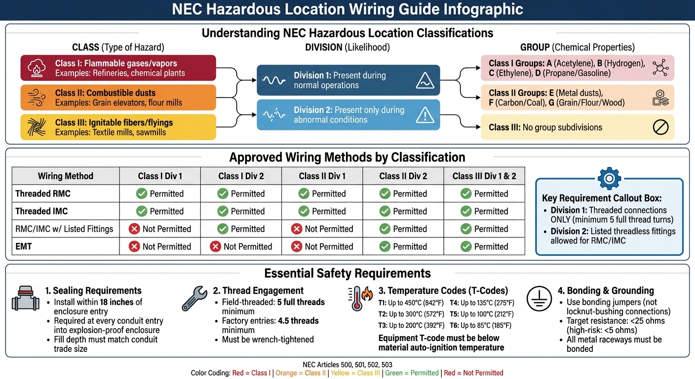
NEC Hazardous Location Classifications and Approved Wiring Methods Guide
Hazardous Classified Locations, NEC 2020 - [500.5], (17min:43sec)
sbb-itb-501186b
NEC Hazardous Location Classifications
The National Electrical Code (NEC) provides a structured system for identifying and managing hazardous locations. These classifications focus on three main factors: the type of material (Class), the likelihood of the hazard being present (Division), and the chemical properties of the material (Group). This system, outlined in NEC Article 500, ensures that wiring methods and equipment are suited to the specific risks of each environment. Understanding these classifications is critical for maintaining safety in hazardous areas.
Class refers to the nature of the hazardous material. Class I locations involve flammable gases, vapors, or liquids; Class II locations deal with combustible dusts; and Class III locations concern ignitable fibers or flyings. Division indicates how likely it is for the hazard to be present. Division 1 means the hazardous material exists during normal operations, maintenance, or equipment failure. Division 2 refers to areas where hazards are usually contained but may appear under abnormal conditions, such as a system rupture. Group narrows the classification further based on chemical properties: Class I includes Groups A through D, Class II has Groups E through G, and Class III has no group subdivisions.
Temperature codes, ranging from T1 (up to 450°C/842°F) to T6 (up to 85°C/185°F), define the maximum surface temperatures of equipment. The T-code must always stay below the auto-ignition temperature of the material in the environment. With these basics in mind, let’s dive into the details of each class.
Class 1: Flammable Gases and Vapors
Class I locations are areas where flammable gases, vapors, or liquids can mix with air to form explosive or ignitable atmospheres. Examples include petroleum refineries, chemical plants, and gas compressor stations. In Division 1, these flammable atmospheres are present during normal operations, such as the vapor above an open gasoline tank or near an active paint spray booth. In Division 2, the hazard is typically contained but may escape due to abnormal events, like a valve failure or a container rupture.
Class I is divided into four groups based on ignition characteristics. Group A includes acetylene, Group B covers hydrogen and similar gases, Group C involves ethylene and related materials, and Group D - most common - includes propane, gasoline, and natural gas. Using fittings specific to the group is crucial to prevent flame propagation. These groupings play a key role in selecting the right wiring and equipment.
Class 2: Combustible Dusts
Class II locations involve combustible dusts that can form explosive clouds when suspended in air or create ignitable layers on equipment surfaces. Examples include grain elevators, flour mills, coal-handling facilities, metal powder processing plants, and woodworking shops. Some dust types, like grain dust, have auto-ignition temperatures as low as 220°C (428°F), making temperature control a priority.
In Division 1, combustible dust is present in the air during normal operations or when conductive dust, like metal powder, poses a risk. For instance, a bucket elevator in a grain elevator during regular use would fall under Division 1. Division 2 applies when dust accumulations could affect heat dissipation or ignite during abnormal equipment operation.
Class II is further categorized by dust type: Group E includes metal dusts like aluminum and magnesium, Group F covers carbon black, coal, and coke dust, and Group G encompasses grain, flour, wood, and plastic dust. Dust-ignition-proof enclosures are essential to prevent dust entry and maintain safe equipment temperatures.
Class 3: Ignitable Fibers and Flyings
Class III locations involve ignitable fibers or flyings, though these materials are typically not present in quantities sufficient to form explosive mixtures. Common examples include textile mills, cotton processing facilities, wood-processing plants, and sawmills. Unlike Classes I and II, Class III has no group subdivisions, simplifying the protective requirements.
In Division 1, fibers or flyings are actively processed or handled, like on a cotton gin or a textile weaving floor. Division 2 applies to areas where these materials are stored or handled without active processing, such as a cotton bale warehouse or lumber storage yard. While the wiring requirements for Class III are less stringent than those for Classes I and II, precautions are still needed to prevent ignition from overheated equipment or arcing contacts.
These classifications serve as a foundation for selecting the proper wiring and equipment, ensuring safety in hazardous environments. Details on specific wiring methods follow in later sections.
Approved Wiring Methods for Hazardous Locations
The NEC lays out specific wiring methods for hazardous areas in Articles 501, 502, and 503. These methods vary depending on whether the location is classified as Division 1 or Division 2. Division 1 zones face continuous exposure to hazardous substances during normal operations, while Division 2 areas only encounter such risks during abnormal events, like equipment malfunctions or container leaks. Below is a breakdown of the approved wiring methods for each classification.
Class 1 Wiring Methods
Article 501 focuses on Class I locations, where flammable gases and vapors pose ignition risks. For Division 1, the NEC mandates the use of threaded Rigid Metal Conduit (RMC) or threaded steel Intermediate Metal Conduit (IMC). These threads must engage at least five full turns when tightened with a wrench, a feature designed to cool and contain any escaping burning gases. Approved threaded RMC couplings are marked with an "EC" to confirm compliance with UL standards.
For Division 2, approved methods include threaded RMC or IMC, as well as RMC or IMC paired with listed fittings. When installing conduits underground, non-metallic options like PVC, RTRC, or HDPE must be buried at least 24 inches deep, transitioning to metal conduit for the final 24 inches before surfacing.
"Rigid and intermediate metal conduits are permitted in all hazardous locations."
– Steel Tube Institute
Class II locations, which involve combustible dust hazards, require equally strict wiring measures tailored to their unique risks.
Class 2 Wiring Methods
Article 502 governs Class II locations, where combustible dust can infiltrate and ignite. In Division 1 areas, only threaded RMC or threaded steel IMC are allowed to prevent dust entry and contain ignition sources. Division 2 expands the options to include Electrical Metallic Tubing (EMT) alongside threaded RMC, IMC, and RMC/IMC with listed fittings. For EMT, all fittings must be specifically listed for Class II environments to ensure safety.
Class 3 Wiring Methods
Article 503 covers Class III locations, which deal with ignitable fibers and flyings. Both Division 1 and Division 2 allow the use of RMC, IMC, and EMT. Since fibers and flyings carry a lower ignition risk compared to gases or dust, the focus here is on avoiding ignition from overheated equipment or electrical arcs.
| Location Class | Division 1 Approved Methods | Division 2 Approved Methods |
|---|---|---|
| Class I | Threaded RMC, Threaded IMC | Threaded RMC/IMC, RMC/IMC with listed fittings |
| Class II | Threaded RMC, Threaded IMC | Threaded RMC/IMC, RMC/IMC with listed fittings, EMT |
| Class III | RMC, IMC, EMT | RMC, IMC, EMT |
Standard locknut-bushing or double-locknut connections are not allowed in these environments. Instead, use bonding jumpers or other approved bonding methods as outlined in Article 250.100. Always consult with the local Authority Having Jurisdiction (AHJ) to ensure compliance, as they have the final say on electrical installations in classified areas.
Wiring Materials and Their Applications
Common Wiring Materials
Choosing the right wiring materials is crucial for adhering to the approved wiring methods. Rigid Metal Conduit (RMC) and Intermediate Metal Conduit (IMC) are widely used and comply with NEC standards for all hazardous locations. These materials feature NPT threads that engage for at least five full turns. This threading design helps cool burning gases from internal explosions as they pass through, preventing ignition of the surrounding flammable atmosphere.
For less hazardous environments, Electrical Metallic Tubing (EMT) offers a lightweight option. However, EMT is not suitable for high-risk areas due to its thin-walled construction and reliance on listed threadless fittings instead of threaded connections. Its use is limited to Class II, Division 2, and Class III locations, where hazards are either less severe or occur only under abnormal conditions.
Standard threaded RMC couplings are marked with an "EC" stamp, indicating compliance with UL listing standards. To ensure proper electrical continuity, approved bonding jumpers should replace standard locknut-bushing connections.
Wiring Materials Comparison
| Wiring Method | Class I, Div 1 | Class I, Div 2 | Class II, Div 1 | Class II, Div 2 | Class III, Div 1 & 2 | NEC References |
|---|---|---|---|---|---|---|
| Threaded RMC | Permitted | Permitted | Permitted | Permitted | Permitted | Arts. 501, 502, 503 |
| Threaded IMC | Permitted | Permitted | Permitted | Permitted | Permitted | Arts. 501, 502, 503 |
| RMC/IMC w/ Listed Threadless Fittings | Not Permitted | Permitted | Not Permitted | Permitted | Permitted | Arts. 501, 502, 503 |
| EMT | Not Permitted | Not Permitted | Not Permitted | Permitted | Permitted | Arts. 502, 503 |
The main distinction between Division 1 and Division 2 installations lies in the threading requirements. Division 1 installations require threaded connections exclusively, while Division 2 allows listed threadless fittings for RMC and IMC. This difference reflects the reduced risk in Division 2 areas, where hazardous conditions are typically limited to equipment malfunctions or abnormal events. The table highlights how matching wiring materials to the specific risks of each location is essential for safety and compliance.
Sealing, Bonding, and Grounding Requirements
Once you've chosen the right wiring materials, the next step is ensuring proper sealing, bonding, and grounding to contain hazards effectively.
Sealing Requirements
Sealing fittings play a critical role in stopping flammable gases, vapors, or flames from traveling through conduit systems. According to NEC Article 501.15, these fittings must be installed at every conduit entry point into an explosion-proof enclosure and at boundaries where conduit exits a classified location. Placement is crucial - seals must be installed within 18 inches of the enclosure entry and filled with an approved sealing compound to a depth matching the conduit's trade size.
The primary goal of these seals is to confine explosions and prevent them from spreading to other parts of the electrical system. A common error is using non-explosion-proof fittings between the seal and the enclosure, which violates NEC 501.15(A).
"The threaded connections allow the burning gas to cool as it escapes, so that any explosion would be confined to the inside of the conduit." – Steel Tube Institute
Before concealing any sealing installations, it's essential to have them inspected by the AHJ (Authority Having Jurisdiction).
Bonding and Grounding Best Practices
Bonding and grounding are key to reducing ignition risks caused by static discharge, arcing, or overheating. Grounding helps stabilize voltage levels and offers protection against lightning strikes, while bonding ensures all metallic components are connected to create a low-impedance fault path. In hazardous locations, all metal raceways and enclosures must be bonded, regardless of circuit voltage.
Standard locknut-bushing and double-locknut connections are insufficient for bonding in hazardous areas. Instead, use bonding jumpers with approved bushings, threaded bosses, or other listed alternatives. For liquid-tight flexible metal conduits, NEC Articles 501.30(B), 502.30(B), and 503.30(B) mandate using a bonding jumper to maintain continuity, as the conduit itself cannot reliably serve as the ground connection.
"In hazardous classified locations, do not depend on locknut bushings and double locknuts for bonding raceways to enclosures." – Consulting - Specifying Engineer
When using bonding jumpers in Class I and II locations, install them on the outside of flexible raceways. This allows maintenance teams to easily verify continuity at a glance. Avoid wrapping the jumper around the flexible connection, as this can create an inductive choke. To ensure effectiveness, bonding resistance between surfaces should stay below 25 ohms, with high-risk applications aiming for 5 ohms or less.
Safety Tips for NEC Compliance in Hazardous Locations
Staying compliant with NEC standards in hazardous locations isn't just about proper installation - ongoing inspections and a keen eye for potential issues are key to avoiding dangerous situations and costly violations.
Inspection and Maintenance Recommendations
Pay close attention to thread engagement in all field-threaded connections. Ensure that threaded conduits are wrench-tightened to engage at least five full threads for field-threaded connections and 4.5 threads for factory entries. This level of engagement is critical to prevent sparking when fault current flows through the conduit system and to maintain the explosionproof or flameproof integrity of the system where required.
Unused enclosure openings should always be sealed with listed metal plug closures. Check that sealing fittings are properly filled with an approved compound to a depth that matches the conduit's trade size, and confirm these fittings are positioned within 18 inches of enclosure entries. Also, keep hazardous area classification drawings up to date, especially after process changes like introducing new chemicals or altering ventilation systems.
Another essential step is verifying that equipment T-codes align with the auto-ignition temperatures of the materials present. Catching these discrepancies during installation can save time and ensure safety during regular maintenance.
Common Mistakes to Avoid
Beyond inspections, avoiding common installation errors is crucial for maintaining safety. For starters, improper bonding is a frequent issue - make sure all wiring and bonding follow NEC standards as outlined earlier.
Incorrect equipment markings are another pitfall. Mislabeling Class, Group, or temperature ratings not only violates NEC rules but also increases the risk of ignition. Don’t rely on chemical similarities to assume Group ratings. For example, ethylene oxide falls under Group C, while acetone is classified as Group D, and each requires different safety measures.
Thread mismatches are another hazard, especially when metric-threaded equipment is connected to NPT fittings without the proper listed adapters. If equipment is located on a classification boundary, always adhere to the stricter classification requirements. For intrinsically safe systems, ensure that IS wiring is physically separated from non-IS wiring in conduits and install the necessary barriers in unclassified areas. These precautions can make a significant difference in maintaining both safety and compliance.
Conclusion
Precision in wiring practices and a clear understanding of NEC classifications play a critical role in ensuring safety in hazardous locations.
Key Takeaways
The Class, Division, and Group classification system is the backbone of safe electrical design in hazardous environments. Proper wiring methods, such as using Rigid Metal Conduit (RMC) or Intermediate Metal Conduit (IMC) with explosion-proof sealing fittings, are essential. These fittings must be installed within 18 inches of enclosure entries to minimize risks. It's also important to ensure all equipment complies with NEC standards and is properly marked. Matching T-codes to specific material hazards is a key step in preventing ignition risks.
Keeping classified area drawings up-to-date is crucial, along with ensuring proper bonding and grounding to avoid compliance issues. OSHA supports these safety measures by referencing NEC Article 500 in 29 CFR 1910.307.
Resources for Further Assistance
The National Fire Protection Association (NFPA) offers essential resources like the National Electrical Code (NFPA 70), alongside recommended practices such as NFPA 497 for flammable liquids and gases and NFPA 499 for combustible dusts. For petroleum facilities, API Recommended Practice 505 provides additional industry-specific guidance. Local AHJs (Authorities Having Jurisdiction) enforce compliance through permit reviews and inspections, so submitting classified area drawings early can help verify equipment ratings.
For sourcing NEC-compliant materials and certified equipment, Electrical Trader (https://electricaltrader.com) is a reliable marketplace. They offer a wide selection of power distribution equipment, breakers, transformers, and conduit systems tailored for hazardous locations. Whether you're an electrician, contractor, or facility manager, having access to properly rated materials is essential for achieving compliance. Combining these resources with diligent on-site practices ensures safe and effective installations in hazardous environments.
FAQs
How do I determine the right Class, Division, and Group for my area?
To determine the appropriate Class, Division, and Group for your location, you'll need to refer to the NEC (National Electrical Code) classifications for hazardous areas. Here's a quick breakdown:
- Classes (I, II, III) categorize the type of hazard present, such as flammable gases, combustible dust, or ignitable fibers.
- Divisions (1, 2) specify how often the hazardous material is present - whether it's a constant risk or only under abnormal conditions.
For a precise evaluation, consult the NEC standards alongside a HazLoc guide. This ensures you select the correct wiring methods and equipment for safe installation.
When are threaded conduit connections required vs. listed threadless fittings?
Threaded conduit connections are essential in hazardous locations due to their strong mechanical durability and reliable grounding capabilities. On the other hand, listed threadless fittings are generally not appropriate for explosion-proof settings and often fail to meet necessary safety requirements. It's crucial to follow NEC (National Electrical Code) guidelines when choosing fittings for these environments to ensure safety and compliance.
How do I choose the correct T-code for equipment in a hazardous location?
To pick the appropriate T-code for equipment in a hazardous location, start by identifying the classification of the area as defined by the National Electrical Code (NEC). This includes determining the class (I, II, or III) and division (1 or 2). This step is typically handled by qualified professionals and must be approved by the Authority Having Jurisdiction (AHJ).
Once the classification is established, select NEC-approved wiring methods and equipment that align with the specific classification. Options like Rigid Metal Conduit (RMC) or Intermediate Metal Conduit (IMC) are commonly used, ensuring compliance with all applicable safety standards.





