
NEC Wiring Methods for Industrial Underground Systems
Underground electrical installations in industrial settings must meet strict safety standards outlined by the National Electrical Code (NEC). These guidelines ensure safe operations, reduce risks, and help pass inspections. Here's a quick summary of what you should know:
- Wiring Types: Approved options for underground use include Type UF, USE, and MC cables. All conductors must be rated for wet locations (e.g., THWN, XHHW).
- Raceways: Use Rigid Metal Conduit (RMC), Intermediate Metal Conduit (IMC), or Schedule 80 PVC for protection. Metal raceways can serve as the grounding path, but nonmetallic ones require a separate grounding conductor.
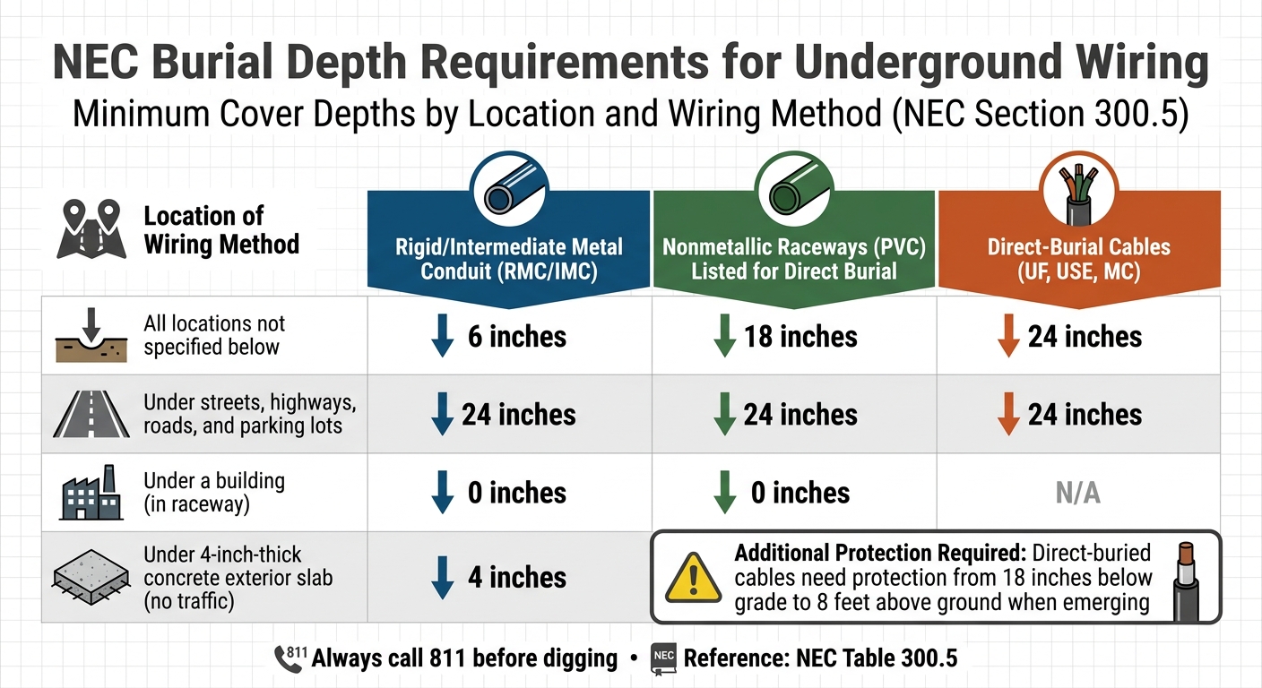
- Burial Depths: Depth varies by method - direct-burial cables need 24 inches of cover, while RMC/IMC requires just 6 inches in certain areas.
- Grounding: Proper grounding and bonding are critical for safety. Nonmetallic raceways require additional equipment grounding conductors.
- Moisture Protection: Underground systems are classified as wet locations. Seal all entry points and use appropriate materials to prevent water intrusion.
Key Tip: Always call 811 before digging to locate existing utilities and avoid accidents.
UNDERGROUND INSTALLATIONS-NEC 2023 SECTION 300.5(B) to (H)
sbb-itb-501186b
NEC Requirements for Industrial Underground Wiring
NEC Underground Wiring Burial Depth Requirements by Location and Conduit Type
The National Electrical Code (NEC) lays out specific guidelines for underground wiring in industrial settings. NEC Section 300.5 is the go-to reference, covering everything from raceways and cables to burial depths and protection methods. As Mike Holt explains, Article 300 focuses on the installation, routing, splicing, protection, and securing of conductors and raceways. These standards apply to a variety of industrial environments, including manufacturing plants and distribution centers, and serve as the foundation for the wiring types, conduit specifications, and burial requirements outlined below.
Approved Wiring Types and Materials
Choosing the right wiring for underground installations is essential to comply with NEC Section 300.5. For direct burial, approved options include Type UF (Underground Feeder), Type USE (Underground Service-Entrance), and Type MC (Metal-Clad) cables specifically rated for such use. Additionally, all underground conductors must be rated for wet locations, as stated in NEC Sec. 310.10(C). Popular insulation types that meet this requirement include THWN, XHHW, and USE.
When physical damage is a concern, the NEC requires conductors to be enclosed in protective raceways such as Rigid Metal Conduit (RMC), Intermediate Metal Conduit (IMC), Reinforced Thermosetting Resin Conduit (RTRC-XW), or Schedule 80 PVC. For splicing direct-buried cables, NEC Sec. 110.14(B) allows splices without a box, provided they are made with methods rated for wet locations and direct burial.
Conduit and Raceway Specifications
Raceway systems are often preferred for industrial underground wiring due to their durability and protection. Rigid Metal Conduit (RMC) is a top choice, offering excellent mechanical protection and approval for use in all locations, including hazardous areas and concrete encasements. Intermediate Metal Conduit (IMC) is another option, providing similar protection at a lighter weight - about 30% lighter than Electrical Metallic Tubing (EMT) over a 100-foot run of 1-inch conduit.
For installations requiring corrosion resistance or cost efficiency, Schedule 40 and Schedule 80 PVC conduits are commonly used. Both are approved for direct burial and concrete encasement, but Schedule 80 is required where raceways are exposed to potential physical damage. Schedule 40 is suitable for standard burial applications.
It’s important to note that metal raceways can serve as the equipment grounding conductor (EGC), while nonmetallic systems like PVC cannot. For PVC raceways, a separate EGC must be installed. Additionally, NEC Chapter 9, Table 1 limits conduit fill to 40% when three or more conductors are installed in a single run.
Burial Depth and Location Requirements
The required burial depth depends on the wiring method used. For direct-burial cables like Type UF, USE, or MC, a minimum cover of 24 inches is necessary for 120/240V circuits. Raceway systems allow for reduced cover depths: Rigid/Intermediate Metal Conduit (RMC/IMC) requires just 6 inches in areas not prone to physical damage, while nonmetallic raceways such as PVC need 18 inches in general installations. However, all wiring methods require a 24-inch cover when installed beneath streets, highways, or parking lots. Under buildings, no additional cover is needed if the wiring is enclosed in a raceway. Similarly, installations beneath a 4-inch-thick concrete exterior slab (without traffic) require only a 4-inch cover.
| Location of Wiring Method | Rigid/Intermediate Metal Conduit (RMC/IMC) | Nonmetallic Raceways (PVC) Listed for Direct Burial |
|---|---|---|
| All locations not specified below | 6 inches | 18 inches |
| Under streets, highways, roads, and parking lots | 24 inches | 24 inches |
| Under a building | 0 (in raceway) | 0 (in raceway) |
| Under 4-inch-thick concrete exterior slab (no traffic) | 4 inches | 4 inches |
For direct-buried cables, additional protection is required from 18 inches below grade to 8 feet above ground as they emerge. Furthermore, underground service conductors must include a warning ribbon placed in the trench at least 12 inches above the installation to alert future excavators. To prevent moisture from contacting energized parts within underground raceways, a sealant compatible with the cable insulation should also be applied.
Installation Methods for Industrial Underground Wiring
Site Preparation and Planning
Start by surveying the site to identify the best cable route while avoiding obstacles like rocks, roots, and existing utilities. This stage also involves calculating the circuit load to determine the appropriate conductor gauge and conduit diameter.
Before digging, contact your local utility locating service by dialing 811 at least three working days in advance. This step is legally required to prevent accidents and ensure all existing underground utilities are marked. Once the route is mapped and cleared, excavate trenches to the depths specified in NEC Table 300.5. Make sure the trench is free of sharp debris, rocks, and standing water. In areas with rocky or harsh soil, add a 3-inch sand layer at the trench bottom to cushion the cable or conduit and protect it from damage.
Cable Laying and Conduit Placement Techniques
When laying conductors, ensure all conductors of the same circuit - neutral and equipment grounding conductor included - are installed in the same raceway or trench. This prevents inductive heating. Use expansion or deflection fittings as needed to handle thermal expansion and contraction, and seal raceway ends with proper materials, such as electrical duct seal, to block moisture. Avoid using standard expanding foams meant for building insulation.
As conductors exit the ground, protect them with Schedule 80 PVC, RMC, IMC, or RTRC-XW. This protection must extend at least 18 inches below ground and 8 feet above ground. Add bushings or fittings at the raceway ends to shield cables from abrasion. Before backfilling, leave 3 feet of extra cable at connection points for future repairs or adjustments, and check continuity and voltage with a multimeter to avoid re-excavation.
When backfilling the trench, do it in 4-inch layers, tamping down each layer to eliminate air pockets and prevent settling. Ensure the backfill material is free from large rocks or sharp objects that could harm the wiring. Finally, document the buried lines by noting their depth, cable type, and the location of junction boxes relative to fixed landmarks like building corners. This record will be invaluable for future maintenance. With the cables securely placed, the next step is to establish a reliable grounding and bonding system.
Grounding and Bonding Requirements
After placing the cables, grounding and bonding are critical for safety. Metal raceways and enclosures must be metallically joined into a continuous electrical conductor to create an effective ground-fault current path.
"The purpose of electrical continuity between metal parts is to establish the effective ground-fault current path necessary to operate the circuit overcurrent protective device in the event of a ground fault".
This ensures that fault currents can safely return to their source and activate overcurrent protection devices.
For nonmetallic raceways like PVC, a separate equipment grounding conductor (EGC) is required, as the conduit itself cannot act as a grounding path. The EGC size depends on the overcurrent protection device rating, as outlined in NEC Table 250.122. For instance, a 100-amp circuit requires at least an 8 AWG copper EGC, while a 200-amp circuit needs a 6 AWG conductor. When using parallel underground conductors in separate nonmetallic raceways, reduce inductive heating at terminations by employing aluminum locknuts and cutting slots between individual holes.
All available grounding electrodes at the site - such as concrete-encased rebar, metal water pipes, or ground rings - must be bonded into a single grounding electrode system (GES). If using driven ground rods, ensure they achieve a resistance to earth of 25 ohms or less. If this resistance isn't met, a supplemental electrode will be necessary. Use the fall-of-potential method, as described in IEEE Standard 81, to measure electrode resistance before backfilling the trenches.
Safety and Maintenance for Underground Systems
Inspection Schedules and Procedures
Before activating any new underground system, conduct insulation resistance tests and continuity checks on all conductors to ensure proper functionality. For conduit installations, a 3.25-inch mandrel should be used in a 4-inch conduit to confirm there are no obstructions and that the joints are properly aligned before proceeding with cable installation.
Routine inspections should target visible warning signs that could indicate issues. When working in or near manholes with energized cables, look for oil or compound leaks from joints or cables, damaged cable sheaths or joint sleeves, localized overheating, and joints that appear swollen beyond normal limits. OSHA mandates treating these conditions as signs of potential faults. In setups with multiple cables, always identify the specific cable through electrical testing unless it is clearly distinguishable by its appearance or location. Once inspections are complete, the focus should shift to measures that protect the system from environmental wear and tear.
Protection Against Environmental Damage
According to the NEC, all underground conduit installations are considered wet locations, even if they are not directly exposed to rain. This classification highlights moisture as a constant threat, capable of corroding metallic parts and degrading insulation not rated for wet conditions. To combat this, seal all building and junction box entries with approved watertight fittings to prevent water intrusion. Regularly inspect these entry points to ensure they remain sealed, using duct seal or mechanical plugs to block water, insects, and rodents. For long outdoor PVC conduit runs, install expansion fittings to accommodate thermal expansion and contraction, which can otherwise strain joints and fittings over time.
Soil quality also plays a crucial role in maintaining system durability. Contaminated soil can accelerate corrosion of metallic conduits. Additionally, sharp stones or debris in the trench can create concentrated pressure points that weaken or puncture conduit walls over time. To mitigate these risks, place a 4- to 6-inch layer of fine sand or granular material both below and above the conduit to evenly distribute soil pressure. Vertical risers emerging from the ground are particularly vulnerable to physical impacts, such as those from mowers or vehicles. Use Schedule 80 PVC or Rigid Metal Conduit in these areas for added protection. With proper design and maintenance, underground conduit systems can typically function reliably for 20 to 40 years.
Common Hazards and Mitigation Strategies
To reduce risks during excavation, reinforce all safety protocols to avoid damaging existing utilities. Striking underground utilities remains one of the most frequent hazards. Always contact 811 at least 10 to 14 days before excavation to locate existing utilities and prevent accidental damage. Ensure warning markers are clearly visible as required. For conductors emerging from the ground, provide physical protection that extends at least 18 inches below grade and 8 feet above ground.
Electrical faults often develop over time. As OSHA Standard 1926.965 explains:
"The employer shall treat the following abnormalities as indications of impending faults... Oil or compound leaking from cable or joints, broken cable sheaths or joint sleeves, hot localized surface temperatures of cables or joints, or joints swollen beyond normal tolerance".
During cable installation, use a tensiometer to monitor pulling tension and ensure it does not exceed the manufacturer's maximum rated pulling force. In hazardous locations where flammable gases, combustible dust, or ignitable fibers are present, install seal-off fittings to block explosive gases from traveling through the conduit system. For manholes deeper than 4 feet, always use a ladder or climbing device - never step on cables or hangers.
Conclusion
NEC-compliant underground wiring serves as the cornerstone of a safe and long-lasting electrical system. As Mike Holt explains:
"Article 300 is primarily concerned with how to install, route, splice, protect, and secure conductors and raceways. How well you understand and apply the requirements of this Article will usually be evident in the finished work. Many of its requirements affect the appearance and longevity of the installation".
By adhering to NEC Article 300.5, you minimize fire and shock hazards during installation and future excavation. This not only ensures your system passes inspection on the first try but also promotes long-term efficiency and safety.
Each step in the installation process builds toward a reliable underground wiring system. NEC compliance plays a key role in maintaining efficiency. For example, conduit systems allow for easy conductor replacement without the need for re-trenching. Properly joined metal raceways and enclosures provide a dependable ground-fault current path, ensuring overcurrent devices respond correctly during faults. Additionally, using wet-rated conductors like THWN or XHHW-2 helps prevent premature insulation breakdown.
The Electrical Trade Network highlights an important point:
"Selecting the wrong wiring method is among the most common causes of failed inspections and code violations, making accurate classification a foundational skill for any licensed electrical trade professional".
Always consult NEC requirements to ensure proper use of NRTL-listed components.
When purchasing materials for underground installations, prioritize both quality and compliance. Trusted suppliers like Electrical Trader offer a wide range of NRTL-listed products, including conduit, fittings, breakers, transformers, and grounding equipment. Whether you need Rigid Metal Conduit for superior mechanical protection or Schedule 80 PVC for corrosive environments, sourcing verified materials reduces guesswork and lowers the risk of inspection issues.
Careful planning is essential. Verify NEC burial depths and remember to call 811 at least 10–14 days before digging. By combining high-quality materials, correct installation practices, and strict adherence to NEC standards, you can create an underground wiring system designed to deliver reliable performance for decades.
FAQs
When should I choose direct-burial cable vs conduit?
When planning your installation, direct-burial cable is a practical choice for simpler setups. If the cable is rated for direct burial and the surrounding conditions are appropriate, this option keeps costs low while streamlining the process.
On the other hand, conduit is the better option if you need extra protection or anticipate future changes. Conduit safeguards cables from physical damage, moisture, and challenging soil conditions. It’s especially useful in tougher environments or when you want the flexibility to upgrade wiring later.
How do I size the equipment grounding conductor for PVC conduit runs?
To determine the correct size for an equipment grounding conductor when using PVC conduit, you’ll need to follow the guidelines in NEC 250.122. This section outlines the minimum conductor sizes required, based on the rating of the overcurrent protection device.
- Step 1: Identify the circuit's breaker size. This is the starting point for determining the conductor size.
- Step 2: Refer to NEC Table 250.122 to find the corresponding minimum conductor size. For example, a 15A breaker requires a 14 AWG conductor, while a 20A breaker needs a 12 AWG conductor.
Always ensure the conductor size meets NEC requirements to maintain proper fault protection and overall safety.
What causes underground conduit systems to fail early, and how can I prevent it?
Underground conduit systems can run into trouble prematurely, often because of installation mistakes. Issues like outdated wiring, overloading, or poor grounding can cause overheating, fires, or damage to cables. To avoid these problems, it's crucial to follow NEC (National Electrical Code) standards. This includes ensuring the right burial depths, selecting the correct conduit types, and keeping wiring up to date.
Proper planning and thorough site preparation are key steps. Adhering to NEC guidelines not only helps sidestep common pitfalls but also plays a big role in extending the lifespan of your underground systems.


