
NEC 250.53: Grounding Electrode Installation Rules
NEC 250.53 focuses on the proper installation of grounding electrodes, such as rods, pipes, and plates, to ensure electrical systems are safely connected to the earth. This stabilizes voltage levels, protects equipment, and reduces shock risks. Key rules include:
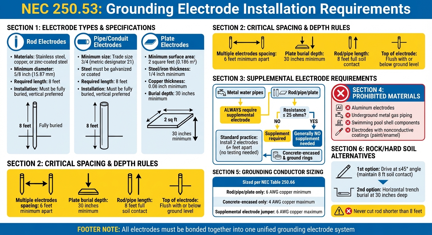
- Rod/Pipe Electrodes: Must be at least 8 feet long and fully buried.
- Plate Electrodes: Require a minimum surface area of 2 square feet and burial depth of 30 inches.
- Spacing: Multiple electrodes must be at least 6 feet apart.
- Supplemental Electrodes: Required unless resistance is 25 ohms or less.
- Prohibited Materials: Aluminum, underground gas piping, or pool shells cannot be used.
Proper materials, burial depths, and compliance with spacing rules are critical. Always bond all electrodes into one system and follow NEC guidelines for sizing conductors and addressing resistance. These steps ensure safe and effective grounding systems for buildings and structures.
NEC 250.53 Grounding Electrode Installation Requirements Quick Reference Guide
Grounding Electrode Conductor Installation and NEC Requirements
sbb-itb-501186b
What NEC 250.53 Requires
NEC 250.53 outlines the rules for grounding electrodes, including metal water pipes, concrete-encased electrodes, ground rings, and rod, pipe, or plate electrodes, as defined in Section 250.52(A). The code specifies how these electrodes should be installed, the materials that are acceptable, and when additional electrodes are needed to ensure safety. Below, we’ll break down what these electrodes do and the compliance standards you’ll need to meet.
What Grounding Electrodes Do
Grounding electrodes connect an electrical system to the earth, helping to stabilize voltage levels and safely direct surge energy.
"The primary purpose of the grounding electrode(s) is to maintain the electrical equipment at the earth's potential present where the grounding electrode(s) is located."
- Joseph Wages, Jr., Director of Digital Education, IAEI
All grounding electrodes in a building - whether metal water pipes, concrete-encased electrodes, or ground rings - must be bonded together to create a unified grounding electrode system.
Compliance Standards You Must Follow
Under NEC 250.53, rod or pipe electrodes must be at least 8 feet long and in full contact with the soil for the entire length. Plate electrodes, which must have a surface area of at least 2 square feet, need to be buried at a minimum depth of 30 inches. If you’re installing multiple electrodes, they must be spaced at least 6 feet apart to avoid resistance interference. Bonding all electrodes into one system is essential to meet the code.
Electrodes must not have nonconductive coatings like paint or enamel, as these can block proper soil contact. A single rod, pipe, or plate electrode must be supplemented with another electrode unless it has a resistance to earth of 25 ohms or less. Metal water pipes used as electrodes always require a supplemental electrode, such as a ground rod or concrete-encased electrode. The code explicitly forbids using underground metal gas piping, aluminum, or metallic parts of swimming pool shells as grounding electrodes.
How to Install Grounding Electrodes
With the NEC requirements in mind, here’s how to properly install grounding electrodes for effective performance.
Approved Materials and Specifications
When it comes to rod electrodes, they must be made of stainless steel, copper, or zinc-coated steel, with a minimum diameter of 5/8 inch (15.87 mm). Smaller diameters are only allowed if the rod is officially listed by a testing laboratory. For pipe or conduit electrodes, the minimum size is trade size 3/4 (metric designator 21). If steel is used, its outer surface must be galvanized or coated to resist corrosion.
Plate electrodes must have at least 2 square feet (0.186 m²) of surface area in contact with the soil. Steel or iron plates need to be at least 1/4 inch thick, while copper plates require a minimum thickness of 0.06 inches. Aluminum is not allowed for grounding electrodes due to its susceptibility to corrosion in soil. Additionally, underground metal gas piping and swimming pool shell components cannot be used as grounding electrodes.
Required Depth and Vertical Placement
For proper installation, rod and pipe electrodes should be installed vertically to maximize soil contact. The top of the electrode must be flush with or below ground level unless both the electrode head and the grounding electrode conductor attachment are shielded from physical damage. Ideally, electrodes should be placed below the permanent moisture level to enhance performance and lower resistance to earth.
Installing in Rock or Hard Soil
If you encounter bedrock during a vertical installation, NEC 250.53(G) outlines alternative methods. Start by driving the electrode at an angle of no more than 45 degrees from vertical. Even at an angle, the electrode must maintain 8 feet of contact with the soil - shortening it is not an option.
If angled installation isn’t feasible due to rock, the next step is to bury the electrode horizontally in a trench at least 30 inches (750 mm) deep. Michael Johnston, retired NECA Executive Director of Codes and Standards, highlights this:
"Laying the rod or pipe electrode in a trench is only a last resort, as indicated by the hierarchy arrangement of 250.53(G)."
He also warns against cutting the exposed portion of the rod to fit:
"The solution is not to cut off the exposed portion of the rod. This results in less than the required NEC minimums for electrode contact with the earth."
- Michael Johnston, NECA Executive Director of Codes and Standards (retired)
Finally, any clamps or connectors used for below-grade connections must be listed for direct burial to ensure they remain reliable in soil conditions.
Next up, we’ll delve into supplemental electrodes and resistance testing to ensure compliance with the 25-ohm standard.
Supplemental Electrodes and Resistance Testing
When You Need Additional Electrodes
Metal underground water pipes should always be supplemented with an additional electrode. This is because water pipes can be replaced or disconnected, potentially disrupting the grounding system. Similarly, rod, pipe, and plate electrodes need supplementation unless a single electrode achieves a resistance of 25 ohms or less. To meet NEC standards, installing two electrodes spaced at least 6 feet apart is sufficient, regardless of the measured resistance.
Michael Johnston, a retired NECA Executive Director of Codes and Standards, explains the reasoning behind this approach:
"The requirement for installing two electrodes reflects how installers typically handle this requirement in the field. The NEC has been improved to require installation of two electrodes as the first priority, rather than installing the second when the 25-ohm resistance is exceeded."
On the other hand, concrete-encased electrodes (commonly known as Ufer grounds) and ground rings generally do not require supplemental electrodes. When bonding a supplemental electrode, it should be connected to one of the following: the grounding electrode conductor, the grounded service-entrance conductor, a nonflexible grounded service raceway, or a grounded service enclosure.
Meeting the 25-Ohm Resistance Standard
Once the electrode system is supplemented, the next step is to ensure it meets the 25-ohm resistance standard. While testing for this resistance is relatively simple, it is rarely performed in practice. This is largely because proper testing equipment can be both complex and expensive, leading many electricians to skip this step.
The recommended method for resistance testing is the fall-of-potential method, which requires a three-terminal earth ground resistance tester. Standard multimeters are unsuitable for this task because they rely on DC current and cannot accurately measure grounding resistance. Ken Michaels underscores the importance of using the right tools:
"You should measure the resistance of an electrode with respect to the surrounding soil in the area. You can only do this by using the fall-of-potential method with a three-terminal, earth ground resistance tester."
In many cases, a practical alternative is to install two properly spaced and bonded ground rods from the outset. When this is done, the NEC considers the system compliant without requiring resistance testing. It's also worth noting that soil resistivity can vary significantly depending on factors like moisture and mineral content, making resistance a "moving target" throughout the year.
Grounding Conductor and Bonding Jumper Sizing
These guidelines ensure the grounding electrode system aligns with NEC standards and maintains proper functionality.
How to Size Grounding Electrode Conductors
The size of a grounding electrode conductor (GEC) is based on the cross-sectional area of the largest ungrounded service-entrance conductor. To determine the correct size, refer to NEC Table 250.66, which provides minimum GEC sizes relative to the service conductor gauge. For instance, if your largest ungrounded conductor is 2/0 AWG copper, Table 250.66 specifies a minimum of 4 AWG copper for the GEC.
For parallel service conductors, calculate the total circular mil area for each phase using NEC Chapter 9, Table 8, and then consult Table 250.66 for the appropriate GEC size. As Md Nazmul Islam explains:
"Where multiple sets of service-entrance conductors are used (parallel sets), the 'Size of Largest Ungrounded Conductor' is determined by the equivalent area of the parallel conductors added together."
When a GEC connects only to a ground rod, pipe, or plate electrode, the minimum size is 6 AWG copper (or 4 AWG aluminum), even if Table 250.66 recommends a larger size. For concrete-encased electrodes (Ufer grounds), the GEC does not need to exceed 4 AWG copper. NEC consultant Mike Holt clarifies:
"The grounding electrode conductor, if it's the sole connection to the ground rod, isn't required to be larger than 6 AWG copper."
However, these exceptions apply only when the conductor connects to a single type of electrode. If the GEC extends to another electrode requiring a larger size, the entire conductor must meet the larger size requirement.
Proper installation of bonding jumpers is also essential for system integrity.
Installing Bonding Jumpers
Bonding jumper sizes are determined using Table 250.66, based on the largest ungrounded phase conductor. For supplemental electrodes, such as a ground rod added to a water pipe system, the bonding jumper does not need to exceed 6 AWG copper.
When running a GEC through a ferrous metal raceway like steel conduit, both ends of the raceway must be bonded to the conductor to avoid "inductive choking", which can increase impedance during fault conditions. Mike Holt explains:
"To prevent inductive choking of GECs, each end of ferrous metal raceways, enclosures, and cable armor containing GECs must be bonded to the GEC... Bonding jumpers must be at least the size of the largest GEC in the raceway."
For bonding jumpers installed within 18 inches of the ground, use copper. To protect GECs smaller than 6 AWG, enclose them in raceways like RMC, IMC, or PVC Schedule 80. Conductors 6 AWG or larger can be installed along building surfaces if they are not exposed to physical damage.
Conclusion
The NEC 250.53 rules form a vital framework to safeguard both people and equipment from hazardous electrical energy. As Joseph Wages, Jr., Director of Digital Education at IAEI, aptly states:
"The safety of the building or structure depends on you."
These rules are designed to ensure electrical systems remain stable during normal operation and provide protection during high-energy events, like lightning strikes or ground faults. The Grounding Electrode System plays a dual role: it stabilizes voltage levels and offers a pathway to safely dissipate dangerous surges. By keeping electrical equipment at the same potential as the earth, proper grounding minimizes the risk of voltage differences that could harm sensitive electronics or pose shock hazards.
The requirement for supplemental electrodes - such as adding a ground rod to a metal water pipe system - ensures the system’s reliability over time. For example, if a metal water main is replaced with plastic piping in the future, the supplemental electrode maintains the grounding system’s effectiveness. Modern buildings, filled with microprocessor-based devices, are especially vulnerable to transient overvoltages. Using durable materials like stainless steel or zinc-coated rods, ensuring electrodes reach the full 8-foot depth, and correctly sizing grounding electrode conductors based on Table 250.66 are all essential steps in creating a grounding system built to last for decades.
FAQs
When can I skip the second ground rod?
If the existing electrode system - like a metal underground water pipe or a concrete-encased electrode - has a ground resistance of 25 ohms or less, you can avoid installing a second ground rod. Another option is to supplement the system with a listed electrode type. As long as the combined setup complies with NEC standards, a second electrode won't be necessary.
How do I ground in bedrock or hard soil?
If you're working with grounding systems and hit solid rock while trying to drive an 8-foot ground rod, NEC 250.53 offers solutions. You can install the rod at an angle of up to 45°, or you can bury it in a trench that's at least 30 inches deep, as long as the rod maintains 8 feet of contact with the soil. If you can only achieve 22 inches of depth, encasing the rod in 2 inches of concrete is an option, though trench burial is generally the better choice.
What ground resistance tester do I need for 25 ohms?
To check resistance of 25 ohms or less, a digital earth resistance tester - such as a Fluke earth ground tester - is the tool you need. Per NEC standards, a resistance reading of 25 ohms or lower indicates that no additional electrode is necessary. Make sure the tester provides an accurate measurement of the resistance between the ground rod and the earth.