
Ultimate Guide to Grounding Residential Electrical Systems
Grounding your home’s electrical system is critical for safety and compliance with the National Electrical Code (NEC). It ensures fault currents are safely directed into the earth, protecting people and property from shocks, fires, and power surges. This guide explains the key components of a residential grounding system and how to install one properly.
Key Takeaways:
- Purpose of Grounding: Prevents electric shocks, stabilizes voltage, and protects against surges or lightning.
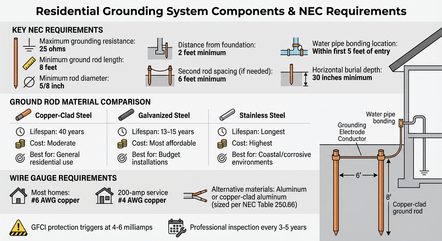
- NEC Standards: Grounding resistance must not exceed 25 ohms; use an 8-foot ground rod or equivalent.
- Core Components: Ground rods, grounding electrode conductor (GEC), clamps, and bonding connections.
- Installation Basics: Place rods in moist soil, use proper clamps, and test resistance to ensure compliance.
- Common Issues: High resistance, loose connections, or improper bonding can compromise safety.
Proper grounding requires careful planning, high-quality materials, and adherence to NEC standards. Regular inspections and maintenance are essential to keep the system functioning effectively.
Residential Grounding System Components and NEC Requirements
Installation of grounding electrodes rods for residential electrical service
Parts of a Residential Grounding System
A residential grounding system is made up of several interconnected parts, all working together to safely channel fault currents away from your home. Each piece plays a critical role in protecting your electrical system. As Dean Austin, Senior Electrical Specialist at NFPA, puts it:
"Grounding is the very foundation of a building or structure's electrical system".
The grounding electrode connects your home to the earth, often using a ground rod, a metal water pipe, or a concrete-encased electrode. The Grounding Electrode Conductor (GEC) is the wire that links your service panel to these electrodes. Within your circuits, Equipment Grounding Conductors (EGC) - those bare copper or green-insulated wires - carry fault currents back to the panel. Meanwhile, the main bonding jumper in your service panel ties the neutral bar to the metal enclosure, ensuring an effective path for ground-fault currents.
Together, these components form a low-resistance path that directs fault currents to trip breakers and cut power to dangerous areas. As Austin emphasizes:
"The earth itself is not considered an effective ground-fault current path, so sticking the wire in the ground is not enough".
It’s the combined effort of these parts - not just any single component - that ensures your home’s electrical safety. Let’s take a closer look at each part and how it contributes to the system.
Ground Rods and Electrodes
Ground rods are metal stakes driven into the earth, designed to safely disperse excess electricity from events like lightning strikes or power surges. According to the NEC, these rods must be at least 8 feet long to ensure proper contact with the soil. There are three common types:
- Copper-clad steel rods: These last about 40 years and are a popular choice.
- Galvanized steel rods: A more affordable option, though their zinc coating typically lasts only 15 years.
- Stainless steel rods: The most durable, ideal for coastal areas with salty air.
For installation, the rod should be driven vertically into moist soil, preferably in areas where rainwater collects. If bedrock prevents an 8-foot depth, the rod can be installed at a 45-degree angle or buried horizontally in a trench at least 30 inches deep. It should also be placed at least 2 feet from your home’s foundation for better soil contact. If the system can’t achieve the required 25-ohm resistance to earth, a second rod must be added, spaced at least 6 feet from the first. Never cut ground rods shorter than 8 feet, as this violates code and reduces safety. For new homes, a Ufer ground - 20 feet of steel rebar or heavy copper wire embedded in the concrete foundation - can serve as an excellent grounding electrode.
Grounding Conductors and Clamps
The Grounding Electrode Conductor (GEC) is the wire that connects the service panel to the grounding electrodes. In most homes, this is 6 AWG copper, though 200-amp services typically need a larger 4 AWG conductor. Copper is the most common material, but aluminum and copper-clad aluminum are also acceptable if sized correctly according to NEC Table 250.66.
Grounding clamps are used to secure these connections. For ground rods, acorn clamps - oval-shaped and designed for direct burial - are recommended. The wire should be positioned in the "V" of the clamp opposite the bolt for a firm hold. For indoor water pipe connections, brass-toothed clamps are preferred because they resist corrosion and maintain conductivity over time. If the GEC passes through a steel conduit or other ferrous metal raceway, the raceway must be bonded to the conductor at both ends to ensure electrical continuity. Regular inspections are essential to prevent corrosion and maintain a reliable connection.
Water Pipes and Bonding
Metal underground water pipes can serve as grounding electrodes but must be paired with another electrode for safety. As Michael McAlister, author of Wiring Complete, explains:
"An underground metal water pipe can't serve as the only grounding electrode. Otherwise, someone could disconnect the pipe or install a section of non-conductive pipe such as PVC, thus interrupting the grounding continuity and jeopardizing your safety".
This backup electrode, often a ground rod, ensures the system remains effective even if future plumbing work replaces metal pipes with non-conductive materials.
Bonding connects all metallic, non-current-carrying parts - like water pipes, gas lines, and appliance frames - to keep them at the same electrical potential. This prevents shocks by ensuring that metal components don’t become energized during a fault. The bonding connection to your water pipe should be made within the first five feet of where it enters the building to maximize earth contact. A brass-toothed clamp is typically used to attach the bonding conductor to the pipe, linking it securely to the service panel’s ground bus.
Bonding creates what the NEC calls an "effective ground-fault current path" (EGFCP), a low-resistance route that allows fault currents to trip breakers or blow fuses quickly. Without proper bonding, metal parts could become live during a fault, posing a serious shock hazard even if grounding electrodes are properly installed.
How to Install a Residential Grounding System
Setting up a residential grounding system requires careful planning and precise work to ensure compliance with NEC standards. The process involves choosing the right location, properly installing ground rods, and making secure connections to protect your home. Following these steps is key to a safe and effective installation.
Safety first. Before you begin, turn off the main breaker and double-check that the panel is de-energized using a voltage tester.
Preparing the Installation Site
The effectiveness of your grounding system depends heavily on where you place the ground rods. Pick a spot close to your main service panel where the soil tends to stay moist, like near downspouts or low-lying areas that collect rainwater. Moist soil improves conductivity, helping to meet the NEC's requirement of 25 ohms of resistance or less.
Before starting, gather these essentials:
Tools:
- Sledgehammer or hammer drill
- Wire strippers
- Pliers
- Voltage tester
- Ground resistance tester
Materials:
- 8-foot ground rods (5/8-inch diameter, copper-clad steel)
- Grounding Electrode Conductor (GEC) (#6 AWG copper for most homes, #4 AWG for 200-amp service)
- Acorn clamps rated for direct burial
Before digging, always check for underground utilities to avoid hazards. If the terrain is rocky and prevents vertical installation, the NEC allows alternative methods, such as angled or horizontal placement.
Once the site is ready and materials are in hand, you can move on to installing the ground rods.
Installing Ground Rods
With safety measures in place, drive the 8-foot ground rod vertically into the soil, maintaining at least 2 feet of distance from the foundation. Use a sledgehammer or hammer drill for this step. The rod's top should sit flush with or slightly below ground level to prevent damage, and cutting the rod is not allowed.
If you hit bedrock or large rocks, you can install the rod at a 45-degree angle or bury it horizontally in a trench about 30 inches deep. As Master Electrician Dustin Stelzer explains:
"Rods may only be installed at an angle if it is not possible to drive the rod eight feet vertically."
Since measuring soil resistance beforehand is tricky, it's common to install two ground rods spaced at least 6 feet apart. For even better performance, some experts suggest spacing them the same distance as their length - 8 feet apart for 8-foot rods.
Once the rods are in place, the next step is connecting the grounding conductors.
Connecting Grounding Conductors
To complete the grounding system, securely attach the continuous #6 or #4 AWG copper GEC to each rod using an acorn clamp. Make sure the conductor remains intact through any conduit. If you're running the GEC through a metal conduit, bond the conduit at both ends to maintain electrical continuity.
Finally, connect the GEC to the grounding bus bar inside the service panel. Double-check that all connections are tight and secure. After everything is connected, use a ground resistance tester to ensure the system measures under 25 ohms. If the resistance is too high, you may need to add more ground rods or reassess the soil conditions. Tighten all clamps and screws to finalize the installation.
sbb-itb-501186b
Testing and Fixing Grounding Problems
To ensure your grounding system is up to code, test it to confirm it meets the NEC's 25-ohm resistance requirement. Keep in mind that factors like soil moisture and temperature can influence your measurements. Having the right tools and methods is crucial for getting reliable results.
How to Test Ground Resistance
The Fall-of-Potential method, also known as the 3-point test, is the most reliable way to measure ground resistance. To perform this test, drive two temporary test probes into the ground in a straight line away from your ground rod. The tester will inject current, measure voltage, and calculate resistance based on Ohm's Law. This method works best for new installations where the ground electrode can be disconnected from the system.
In urban environments with multiple grounding paths, the stakeless method is often more practical. This approach uses two clamps to measure resistance and is suitable for multi-grounded systems, though it may not be as precise. For homeowners, simpler tools like a digital multimeter or a GFCI receptacle tester can be used to confirm outlet grounding.
To test an outlet with a multimeter, measure the voltage between the hot and neutral slots, and then between the hot and ground slots. According to Fluke:
"Electrical systems are only as safe as their grounding".
In a properly grounded outlet, these voltage readings should be nearly identical, typically around 120V.
If your test results reveal grounding issues, refer to the common problems and solutions outlined below.
Common Grounding Problems and Solutions
If your measurements show resistance above acceptable levels, you may be dealing with one of these common problems:
- High resistance: This is often caused by dry soil, corroded electrodes, or ground rods that aren't deep enough. If resistance exceeds 25 ohms, try driving the rod deeper or install a second rod at least 6 feet away.
- Loose or corroded connections: Damaged or corroded clamps can break the low-resistance path to the earth. Inspect all connections and replace any corroded clamps with UL-listed ones.
- Bootleg grounds: These occur when the ground terminal is improperly connected to the neutral wire, a common issue in older homes without dedicated ground wires. Correct this by running a new equipment grounding conductor to the panel or installing a GFCI outlet labeled "No Equipment Ground" as a safer alternative.
Additionally, ensure there is only one neutral-to-ground bond in the system, typically located at the service entrance. Watch for warning signs like flickering lights, buzzing outlets, or mild shocks from appliances - these often indicate grounding issues that require immediate attention.
Buying Grounding Equipment from Electrical Trader

Now that you’re familiar with proper grounding techniques, the next step is finding reliable equipment that meets compliance standards.
Why Choose Electrical Trader for Grounding Supplies?
Electrical Trader simplifies the process of sourcing grounding equipment by offering a centralized marketplace where you can shop for both new and used products from multiple sellers. This eliminates the hassle of juggling different vendors for your residential grounding project. Whether you're a professional electrician or a homeowner collaborating with a contractor, having access to a variety of options helps you manage costs while ensuring quality.
Used equipment can be a budget-friendly choice, especially for items like ground rods and clamps that retain their functionality over time. For instance, galvanized steel rods are the most economical option, while copper-bonded rods strike a good balance between cost, conductivity, and resistance to corrosion. By comparing listings from various sellers, you can find materials that meet NEC standards without overspending.
Here’s a look at some grounding components available through Electrical Trader that align with NEC requirements.
Grounding Products Offered by Electrical Trader
Electrical Trader’s marketplace features all the key items needed for residential grounding projects, including copper-bonded ground rods in standard sizes. Popular options include 1/2" x 8', 5/8" x 8', and 3/4" x 8' rods, with 10-foot rods available for areas requiring deeper installation, such as dry or rocky soils.
In addition to rods, you’ll find grounding electrode conductors (wires) in various gauges to suit different service amperage needs. The platform also provides a range of clamps, such as acorn clamps for direct burial connections and brass-toothed clamps for bonding indoor water pipes.
Electrical Trader goes beyond basic grounding supplies by offering precision testing tools, like earth ground testers and clamp-on testers, to ensure your system meets the 25-ohm resistance standard. You can also browse related service entrance equipment, including panelboards, circuit breakers, and bus bars, for a complete electrical installation setup.
Conclusion
A well-installed grounding system is the foundation of your home's electrical safety. It provides a low-resistance route for fault currents to safely dissipate into the earth, shielding both people and equipment from electrical shocks and potential fires. This setup also ensures compliance with NEC standards, which require grounding systems to maintain a resistance of 25 ohms or less. Meeting this benchmark relies on using high-quality materials and adhering to proper installation methods.
When it comes to ground rods, the material you choose matters. Copper-plated rods offer a service life of about 40 years, while galvanized rods last roughly 13 years under comparable soil conditions. This difference in durability can significantly impact the long-term reliability of your system.
Proper bonding is equally critical. By connecting all metal components, you create a low-impedance path that allows circuit breakers to trip immediately during a fault. Without this bonding, items like metal pipes, appliance frames, or junction boxes can become dangerously energized. Additionally, modern GFCIs enhance safety by cutting power when they detect leaks as small as 4 to 6 milliamps.
Regular maintenance is key to keeping your grounding system in top condition. Professional inspections every 3 to 5 years can help identify issues like corrosion, loose connections, or increased resistance levels. Be alert to warning signs such as flickering lights during storms, buzzing outlets, or mild shocks when touching appliances - these are clear indicators that your system may need attention.
FAQs
Why is grounding resistance important, and how can I ensure it complies with NEC standards?
Grounding resistance plays a key role in electrical safety by ensuring fault currents are safely directed into the ground. A low-resistance path allows circuit breakers to trip quickly during faults, minimizing the chances of electrical shocks, fires, or damage to appliances. It also helps stabilize system voltage during lightning strikes or power surges, offering protection to your home’s electrical system.
To meet NEC standards, refer to Article 250, which specifies the use of an 8-foot ground rod made of copper or uncoated steel, driven into the soil. Be sure to use a properly rated clamp and size the grounding conductor according to NEC Table 250.66. After installation, verify the resistance using a calibrated earth-ground tester. While the NEC generally advises a resistance of 25 ohms or less for a single-rod system, aiming for lower values is ideal, especially in areas with high soil resistivity.
If you’re looking for ground rods, clamps, or testing tools, Electrical Trader has a wide selection of residential grounding components to help you create a safe and code-compliant system.
How can I tell if my home's electrical grounding system needs maintenance or repair?
If your home's grounding system is acting up, there are a few warning signs you shouldn't ignore. For instance, if you feel mild electric shocks or a tingling sensation when touching appliances, metal outlets, or light switches, it could mean something's off. You might also spot flickering or dimming lights, especially when heavy-duty appliances like dryers or air conditioners kick in. Other clues? Frequent bulb burnouts or unexplained power surges.
Keep an eye out for circuit breakers that trip repeatedly, a buzzing or humming sound coming from outlets, or corrosion and rust on the grounding rod or its connections. These issues can weaken your system's safety and reliability.
If any of these signs sound familiar, don't wait - get a licensed electrician to check things out. Need replacement parts? Electrical Trader offers grounding rods, clamps, conductors, and more to ensure your system is up to U.S. code and working as it should.
How can I choose the best ground rod for my home's location and soil type?
Selecting the right ground rod largely depends on your soil type and local conditions. According to the NEC (National Electrical Code), a ground rod must be at least 8 feet long and 5/8 inch in diameter, driven directly into the earth. For most residential soils, standard copper-clad steel rods are a solid choice. However, if you're dealing with rocky or hard clay soils, you might need a stronger rod with a larger diameter, such as 3/4 inch or even 1 inch. In some cases, multiple rods spaced at least 6 feet apart may be necessary.
For regions with corrosive or coastal soils, stainless steel or copper-clad steel rods are better suited due to their durability. On the other hand, galvanized steel rods are a budget-friendly option for areas with non-corrosive inland conditions. Testing your soil’s resistivity can also help you make an informed decision. If the soil has low resistivity (under 100 ohm-meters), a single copper-clad rod is usually sufficient. Higher-resistivity soils, however, might require additional measures like a ground plate or multiple rods to ensure proper grounding.
When installing the rod, make sure it’s placed below the frost line and free from any coatings that could interfere with conductivity. If you're looking for specific sizes or materials, Electrical Trader offers a range of copper-clad, stainless steel, and galvanized ground rods designed to meet the needs of various U.S. soil conditions.


