
4 Methods for Ground Resistance Testing
Ground resistance testing ensures electrical safety by measuring how effectively current flows from a grounding system into the earth. This protects people and equipment from electrical faults or surges. The four main testing methods are:
- Fall-of-Potential (3-Point Test): Best for existing systems, requires stakes and space, but delivers accurate results.
- 4-Point Wenner: Focuses on soil resistivity for new installations, crucial for designing grounding systems.
- Clamp-On Method: Quick and non-disruptive, ideal for live systems, but less precise for absolute resistance.
- Selective Testing: Measures individual electrodes without disconnecting them, suitable for complex setups.
Each method has unique strengths and is suited for specific scenarios, from new installations to maintenance in urban or industrial environments. Regular testing is essential to maintain safety and compliance with standards like NEC's 25-ohm rule or IEEE/NFPA's 5-ohm recommendation for sensitive equipment. Below is a comparison of these methods:
| Method | Accuracy | Tools Required | Disconnection Needed? | Best Application | Key Limitation |
|---|---|---|---|---|---|
| Fall-of-Potential | High | 2 stakes, tester, leads | Yes | New installations, maintenance | Requires space and time |
| 4-Point Wenner | Highest (soil) | 4 stakes, tester | N/A (pre-install) | Soil resistivity testing | Needs open area, sensitive to metals |
| Clamp-On | Moderate | Clamp tester | No | Urban setups, live systems | Measures overall loop resistance |
| Selective Testing | High | Clamp, 2 stakes, tester | No | Industrial systems | Stakes still required |
Choosing the right method depends on the system's needs and environment. Regular testing every 3 years - or more often for critical systems - helps ensure safety and reliability.
Comparison of 4 Ground Resistance Testing Methods: Accuracy, Tools, and Applications
Ground Resistance Testing
sbb-itb-501186b
Fall-of-Potential Method (3-Point Test)
The Fall-of-Potential method, also known as the 3-point test, is a widely recognized approach for measuring ground resistance in existing grounding systems. This method involves injecting current through an auxiliary current electrode (C) and measuring the resulting voltage drop at an intermediate potential electrode (P). The key to accurate readings lies in placing the electrodes outside the "sphere of influence", where the resistance of the tested electrode could interfere with measurements. Using Ohm's Law (R = V / I), the resistance is calculated, and modern digital testers often display the results automatically in ohms.
Proper electrode placement is essential. If the auxiliary stakes are positioned too close to one another, their resistance fields may overlap, leading to distorted results. Additionally, the ground electrode must be completely disconnected from the electrical system (both neutral and ground connections) before performing the test.
Required Tools
To carry out this test, you'll need the following:
- A ground resistance tester (e.g., Fluke 1625-2 GEO)
- Two metal auxiliary stakes
- Insulated test leads
- Measuring tape
- Insulated gloves
- Safety glasses
- Steel-toe boots
Step-by-Step Procedure
- Disconnect the Electrode: Begin by disconnecting the ground electrode from the electrical system to isolate it completely.
- Position the Current Stake (C): Drive the current stake into the ground at a distance appropriate for the electrode's depth. Typically, this distance ranges between 82 and 164 feet (25 to 50 meters) for standard installations.
- Place the Potential Stake (P): Insert the potential stake in a straight line between the electrode and the current stake. Use the 62% rule to determine its placement - about 61.8% of the distance between the electrode and the current stake - to ensure stable readings.
- Connect and Test: Attach the tester's leads to the ground electrode, the potential stake, and the current stake. Activate the tester to inject current between the electrode and the current stake while measuring the voltage drop at the potential stake.
- Verify the Results: To confirm the potential stake is outside the sphere of influence, move it approximately 3 feet (1 meter) closer to the electrode and then 3 feet closer to the current stake. If the readings vary by more than 30%, you'll need to increase the distance between all electrodes and repeat the test.
Standard Distances for Electrode Depths
The table below provides recommended distances for the potential and current stakes based on the depth of the earth electrode:
| Depth of Earth Electrode | Distance to Potential Stake (P) | Distance to Current Stake (C) |
|---|---|---|
| 6.6 ft (2 m) | 49.2 ft (15 m) | 82 ft (25 m) |
| 9.8 ft (3 m) | 65.6 ft (20 m) | 98.4 ft (30 m) |
| 19.6 ft (6 m) | 82 ft (25 m) | 131.2 ft (40 m) |
| 32.8 ft (10 m) | 98.4 ft (30 m) | 164 ft (50 m) |
Source: Compiled from Fluke and Electrical Classroom guidelines.
This table serves as a practical guide for determining stake placement based on the depth of the tested electrode. Proper adherence to these distances ensures accurate and reliable measurements.
4-Point Wenner Method
The Wenner method is specifically designed for new installations, focusing on evaluating soil resistivity rather than testing existing ground electrodes like the Fall-of-Potential method does. Developed in 1915 by Dr. Frank Wenner, this approach plays a key role in designing grounding systems for "green field" applications - areas where no ground electrode is in place yet. By measuring soil resistivity, engineers can determine the depth and configuration of grounding rods needed to meet target resistance levels before installation begins.
This method involves placing four identical electrodes in a straight line, spaced equally apart (spacing "a"). A current is injected through the two outer electrodes (C1 and C2), while the voltage drop is measured between the two inner electrodes (P1 and P2). The resistance (R) obtained from the test is then used in the formula ρ = 2πaR to calculate soil resistivity. The spacing between the electrodes determines the depth of the soil being measured. For instance, a 5-foot spacing gives the resistivity at a 5-foot depth.
"Soil resistivity testing is the single most critical factor in electrical grounding design." - E&S Grounding
According to IEEE Std 80-2013, soil resistivity for high-voltage substations should ideally be below 500 ohm-meters to ensure effective grounding. However, soil resistivity can vary greatly depending on factors like soil composition, moisture levels, and temperature. To minimize errors caused by underground pipes or aquifers, it’s recommended to perform a second round of measurements with the electrode alignment rotated 90 degrees.
Required Tools
To perform the Wenner method, you'll need a ground resistance tester such as the Fluke 1625-2 or Fluke 1623, which includes built-in current sources and calculation features. Additional tools include four identical metal stakes, insulated test leads, a measuring tape, and a hammer or mallet. If testing on hard surfaces, you may need water or conductive mats to improve electrode contact.
Step-by-Step Procedure
Start by selecting a test site near the proposed grounding location, ensuring the area is free of buried metal objects that could interfere with the test. Place four electrodes in a straight line, spaced equally apart, and ensure the depth of each electrode is no more than one-third of the spacing distance.
Connect the tester by attaching the outer electrodes to the current terminals (C1 and C2) and the inner electrodes to the potential terminals (P1 and P2). Set the tester to 4-pole resistance mode and initiate the test. The device will send current through the outer electrodes and measure the voltage drop between the inner electrodes. Record the resistance (R) and calculate soil resistivity using the formula ρ = 2πaR.
To create a detailed soil profile, increase the spacing incrementally by a factor of approximately 1.5 for each subsequent measurement (e.g., 1 foot, 1.5 feet, 2 feet, 3 feet, 4.5 feet). This process helps identify the optimal depth for installing permanent grounding rods. Ensure the test line is sufficiently distanced from any parallel buried metallic structures - at least equal to the pin spacing - to avoid unintentional electrical paths.
Clamp-On Method
The clamp-on method, also known as "stakeless testing" or "induced frequency testing", is ideal for scenarios where disconnecting the ground system isn't feasible or safe. Unlike the fall-of-potential or Wenner methods, this approach allows testing on live, connected systems without needing auxiliary stakes or isolating the electrode. The process involves a clamp-on tester, which uses a transmit coil to induce voltage and a receive coil to measure current. The loop resistance is then calculated using Ohm's Law: R = V / I.
This technique works well when there are multiple ground paths in parallel - such as utility neutrals or several connected ground rods. In such cases, the resistance of parallel return paths becomes negligible, allowing the loop resistance reading to closely reflect the resistance of the electrode being tested. Edvard Csanyi, Founder of EEP - Electrical Engineering Portal, explains, "The more ground electrodes in parallel, the smaller the impact of the resistance of the electrodes not being tested and the closer the loop resistance is to the resistance of the electrode being tested."
"The stakeless method is the preferred method when parallel grounds are present and temporary ground stakes are impractical."
- Fluke
The clamp-on method is quick and convenient, eliminating the need to disconnect systems or run additional cables. However, if the tester displays "OR" (Open Range) or "LOOP", it means the device isn't clamped around a complete circuit or the resistance is too high to measure. This limitation makes the method better suited for maintenance checks on existing systems rather than commissioning new installations, which often lack the parallel paths required for accurate readings.
Required Tools
For this method, you'll need a clamp-on ground resistance tester, such as the AEMC Model 6417 or Fluke 1630-2 FC. These devices contain two internal coils - one for inducing voltage and the other for measuring current. Most testers also include a calibration loop (typically 5.0 ohms) to verify accuracy before testing. If calibration readings seem off, clean the clamp heads using a lint-free cloth or 600-grit sandpaper.
Step-by-Step Procedure
Here’s how to perform the clamp-on test effectively:
- Verify the Circuit: Ensure the system forms a complete electrical circuit. The clamp-on method won't work with isolated grounds due to the lack of a return path.
- Calibrate the Tester: Set the tester to resistance mode (Ω) and use the calibration loop to confirm accuracy. The reading should align with the manufacturer's tolerance (e.g., 5.0 ohms ±0.2 ohms).
- Check for Leakage Current: Switch to current mode (A) and clamp the meter around the ground wire. If leakage current exceeds 10 A, stop testing and investigate the cause.
- Measure Ground Resistance: Return to resistance mode (Ω) and clamp the tester around the ground conductor or electrode. Ensure the clamp fully encloses the conductor.
- Record and Verify: Wait for the reading to stabilize, then record the value. Re-clamp the tester on the calibration loop afterward to confirm the measurement remains accurate.
This method offers a practical and efficient way to measure ground resistance in systems with parallel grounding paths, provided the proper tools and steps are followed.
Selective Testing Method
The selective testing method builds on the Fall-of-Potential technique, offering a way to measure individual electrode resistance without disconnecting it. This approach improves safety by eliminating the risk of exposure to dangerous voltage potentials. As Fluke puts it:
Selective testing is very similar to the Fall-of-Potential testing, providing all the same measurements, but in a much safer and easier way.
Here's how it works: A current clamp isolates the test current flowing through the specific electrode you want to measure. The tester sends a known current between an auxiliary stake and the electrode while a potential stake measures the voltage drop. By using Ohm's Law (R = V / I), the resistance is calculated based solely on the current measured by the clamp. This isolates the electrode's resistance from other grounding influences in systems with multiple ground paths, like high-voltage transmission towers, central offices, or facilities with interconnected grounding systems. Maintaining a 65-foot (20-meter) spacing between stakes generally ensures reliable results.
This method is especially practical when verifying individual components of a complex grounding system. For example, you can measure the main ground network, ground field, and water pipe separately to confirm that their combined parallel resistance aligns with the total system resistance. It complements earlier techniques by providing a safer and more targeted solution for intricate setups.
Required Tools
To perform selective testing, you'll need the following:
- An earth ground tester (e.g., Fluke 1625-2 or 1623-2)
- A current clamp
- Two auxiliary ground stakes
- Test leads to connect the tester to the electrode and stakes
For specialized cases, such as high-voltage transmission towers, you might also need a clamp-on current transformer (e.g., a 320 mm or 12.7-inch model) to measure individual tower legs without disconnecting ground leads or overhead static wires.
Step-by-Step Procedure
Here’s how to carry out a selective test:
- Set up the stakes: Place two auxiliary stakes in a straight line away from the electrode. A spacing of 65 feet (20 meters) typically works well.
- Connect the tester: Attach the ground tester to the electrode of interest, ensuring it remains connected to the grounding system.
- Position the clamp: Place the current clamp around the electrode to measure only the current flowing through it, isolating it from parallel paths.
- Inject current and measure voltage: The tester sends a known current between the auxiliary stake and the electrode while measuring the voltage drop with the potential stake.
- Calculate resistance: The tester uses the voltage drop and the clamp's current reading to automatically calculate the electrode’s resistance.
This method simplifies the process of isolating and analyzing individual components of a grounding system, making it an essential tool for complex setups.
Comparison of Ground Resistance Testing Methods
After walking through the step-by-step guides, it’s time to compare the most common ground resistance testing methods. Each method has its strengths and weaknesses, and picking the right one depends entirely on the situation at hand. Below, we’ll revisit the main methods, focusing on what sets them apart.
Fall-of-Potential is widely regarded as the most dependable option since it fully aligns with IEEE 81 standards. It’s perfect for testing new installations and for routine maintenance. The downside? It requires a lot of space for stakes and can take a fair amount of time to complete.
4-Point Wenner is unmatched when it comes to soil resistivity accuracy, making it a go-to during the design phase of a grounding system. This method involves four stakes and works best in open spaces. According to NEC standards, grounding systems should have resistance levels of 25 ohms or less, though 5 ohms is recommended for more sensitive systems.
Selective Testing strikes a balance, especially for industrial setups with complex grounding systems. It delivers precise results for individual electrodes without requiring disconnection from the system. This is achieved by isolating the test current using a clamp, which eliminates interference from parallel paths.
Clamp-On Testing stands out for its ease and speed - there’s no need for stakes or system disconnections. You simply clamp the tester and take the measurement. However, it’s less precise in measuring absolute ground resistance because it reads the entire loop, including neutral wiring and parallel grounds.
"The clamp-on tester can be an enormous time saver, but unlike its traditional three-point counterpart, it cannot be used everywhere".
This method is ideal for urban areas and systems with multiple grounding points.
Comparison Table
Here’s a quick summary of the methods to help you decide which one fits your needs:
| Method | Accuracy | Tools Required | Disconnection Needed? | Best Application | Key Limitation |
|---|---|---|---|---|---|
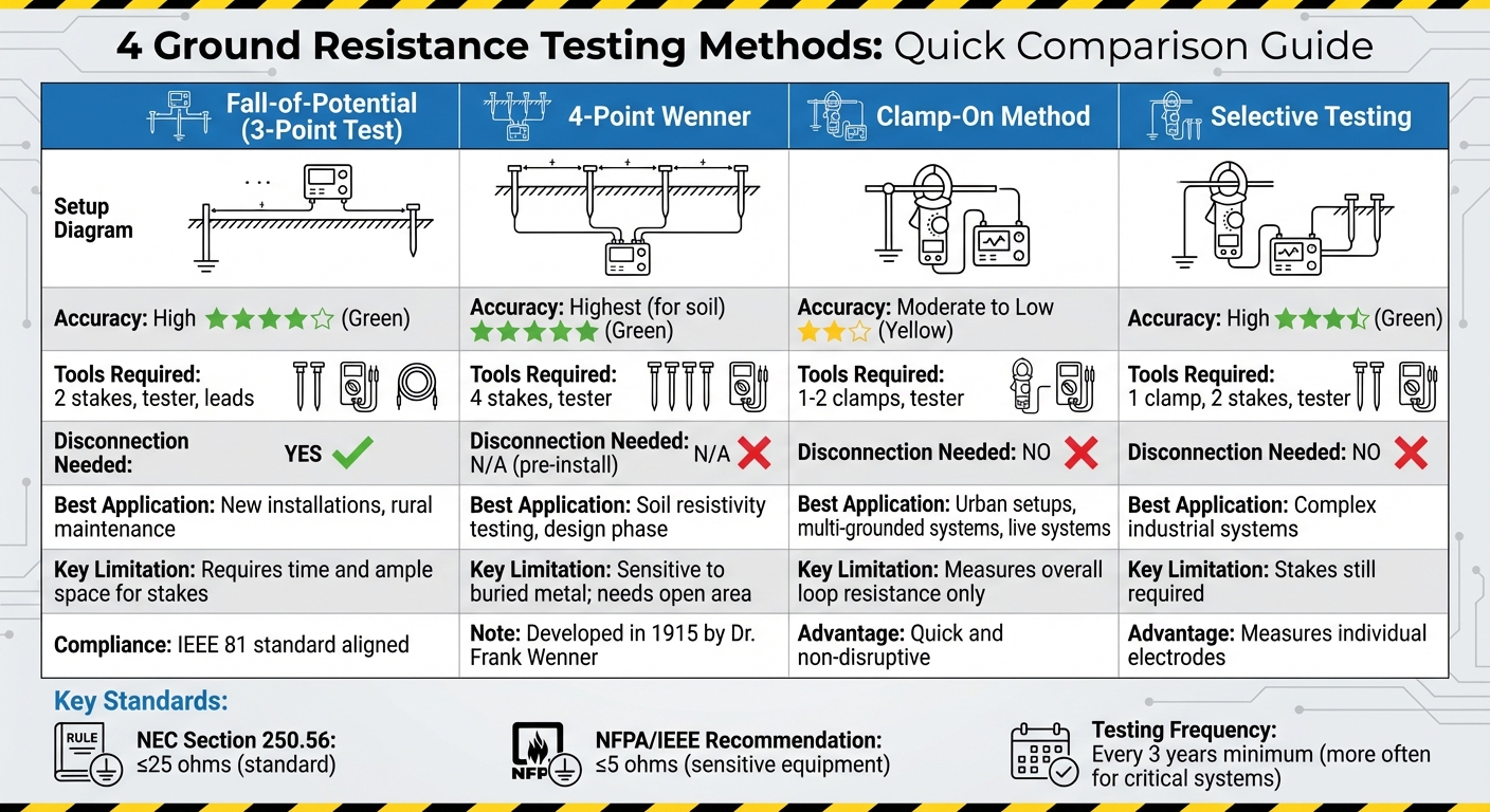
| Fall-of-Potential | High | 2 stakes, tester, leads | Yes | New installations, rural maintenance | Requires time and ample space for stakes |
| 4-Point Wenner | Highest (for soil) | 4 stakes, tester | N/A (pre-install) | Soil resistivity testing, design phase | Sensitive to buried metal; needs open area |
| Selective Testing | High | 1 clamp, 2 stakes, tester | No | Complex industrial systems | Stakes still required |
| Clamp-On | Moderate to Low | 1–2 clamps, tester | No | Urban setups, multi-grounded systems | Measures overall loop resistance only |
This breakdown helps match the method to specific installation and maintenance needs, ensuring the best fit for the job.
Conclusion
Choosing the right ground resistance testing method is essential for ensuring safety, meeting compliance standards, and maintaining the durability of electrical systems. Each method has its own strengths, and understanding when to use each one helps prevent electrical hazards, safeguard equipment, and avoid unnecessary downtime.
The Fall-of-Potential method is ideal for new installations, compliance checks, or when accurate readings are a priority. For pre-construction planning, the 4-Point Wenner method is invaluable for evaluating soil resistivity and designing grounding systems effectively. In urban settings where driving stakes into concrete is challenging, the Clamp-On method provides a quick, non-invasive solution, though it works best in multi-grounded systems with parallel paths. For complex industrial environments, the Selective method allows for testing individual electrodes without needing to shut down the entire system. These methods build on the detailed procedures outlined earlier.
Testing also ensures compliance with standards like NEC Section 250.56's 25-ohm rule and the NFPA/IEEE's 5-ohm recommendation for sensitive equipment. Think of a grounding system as a safety valve: it channels excess current during electrical surges, protecting both systems and people.
Regular testing is just as important as choosing the right method. Ground resistance can change due to factors like moisture, temperature, soil conditions, corrosion, and nearby infrastructure changes. Testing seasonally or at least every three years is critical to maintaining system safety and reliability. Without consistent monitoring, a previously safe system can become a potential hazard over time.
Whether you're working in a rural substation or a bustling urban building, aligning the testing method with your specific environment and system design is key. This approach not only ensures compliance but also protects lives and equipment while keeping systems running smoothly.
FAQs
Which ground resistance test should I use for my site?
The ground resistance test you choose should align with your site's specific needs and conditions. Some widely used methods include fall-of-potential, stakeless testing, soil resistivity measurements, and selective testing. Factors such as the presence of parallel grounds or the need for non-invasive procedures often play a big role in selecting the right approach. Evaluate your site’s unique requirements to ensure you achieve precise and reliable results.
What can affect ground resistance test results?
Factors like soil humidity, soil texture, the size and shape of electrodes, burial depth, the surrounding landscape, and nearby grounding systems can all affect ground resistance test results. These variables play a role in measurement accuracy, making it essential to consider them carefully during testing.
How do I know my reading meets NEC or IEEE/NFPA limits?
To determine if your ground resistance reading is within acceptable limits, refer to these standards: NEC permits up to 25 ohms, while IEEE and NFPA suggest less than 5 ohms for efficient grounding. Make sure your readings fall within these guidelines to ensure compliance and reliable system performance.


