
Partial Discharge Testing: Methods Explained
Partial discharge (PD) testing is essential for maintaining high-voltage electrical equipment. It detects insulation flaws early, preventing costly failures, fires, and safety hazards. PD occurs when electrical discharges partially bridge insulation gaps, often leading to insulation degradation over time. This article breaks down key PD testing methods and their applications:
- IEC 60270 Method: Provides precise, standardized measurements in controlled settings like factories and labs. Requires equipment shutdown.
-
Non-Intrusive Methods: Allow testing on live equipment without interruptions:
- HFCT: Monitors PD signals in cables, transformers, and motors with sensors on grounding conductors.
- TEV: Detects PD in metal-clad switchgear using external sensors.
- UHF: Ideal for Gas-Insulated Switchgear (GIS) due to strong noise resistance.
- Ultrasonic: Uses sound waves to identify surface PD and corona discharges.
- RF: Tracks electromagnetic waves to locate PD sources.
Each method has strengths suited to specific equipment and operational needs. Proper testing ensures reliability, extends equipment life, and minimizes risks.
5.4 Partial Discharges Testing Methods - HFCT sensors
IEC 60270 Electrical Method
IEC 60270 is the go-to international standard for measuring partial discharge (PD) in high-voltage equipment. This method is widely applied to devices tested with DC or AC voltages (up to 500 Hz), including transformers, switchgear, cables, and rotating machinery.
How the Method Works
This method provides a standardized and reliable approach for detecting partial discharges in high-voltage systems. It focuses on measuring apparent charge, the key metric for quantifying PD activity, expressed in picocoulombs (pC). To carry out these measurements, the test setup requires several components:
- A low-noise high-voltage power supply
- A coupling capacitor (Ck)
- Measuring impedance (Zm)
- A quadripole coupling device
- A measuring instrument
The testing process begins by connecting the test object and the coupling capacitor in parallel. Before actual testing, a calibrator injects short-duration current pulses of known charge to establish a unique calibration factor (k-factor), which must be recalibrated if the setup changes.
"The apparent charge of a PD pulse is defined as the charge which, if injected within a very short time between the terminals of the test object in a specified test circuit, would give the same reading on the measuring instrument as the PD current pulse itself." - Omicron
When a partial discharge occurs, the resulting current pulse is converted by the coupling device into an output voltage. The measuring instrument then integrates this signal to determine the apparent charge. According to the standard, the frequency range for wide-band instruments is set between 30–100 kHz and below 1 MHz. Typically, a coupling capacitor with a value of 1 nF or greater is used.
Advantages and Limitations
The IEC 60270 method delivers standardized and repeatable results, making it easier to compare measurements across different environments. Unlike some alternative methods, it provides calibrated results in picocoulombs, ensuring accuracy even when signal attenuation or distortion alters the pulse shape.
However, this method does come with limitations. Since it requires offline testing, the equipment must be disconnected from the power grid and energized using an external power source. The need for galvanic coupling - a direct electrical connection to high-voltage terminals - makes this approach more intrusive compared to sensor-based methods. Additionally, the standard's frequency range (100 kHz to 1 MHz) can leave the system more vulnerable to electromagnetic interference compared to methods operating at higher frequencies.
Despite these challenges, the IEC 60270 method excels in controlled settings such as factory acceptance tests, commissioning, or planned maintenance outages. Its precision and standardization make it the preferred choice in scenarios where accurate PD measurement is critical. While it remains a cornerstone of PD testing, its limitations highlight the growing interest in less invasive, sensor-based alternatives.
Non-Intrusive Testing Methods
Unlike the IEC 60270 method, which requires shutting down equipment and making direct electrical connections, non-intrusive techniques allow testing while keeping the equipment energized and operational. These methods enable assessments under real-world conditions, accounting for factors like actual load, temperature, and humidity - all without causing outages .
Non-intrusive testing relies on sensors placed externally or at ground potential, prioritizing both safety and efficiency. Fernando Álvarez from the Department of Electrical Engineering at Polytechnic University of Madrid highlights this advantage:
"For utilities, the most interesting advantage of on-line PD measurements is that once the sensors are installed in the power grid, the electrical service is not interrupted for the measurements".
Below are some commonly used non-intrusive methods, showcasing how they are applied in real-world scenarios.
High Frequency Current Transformer (HFCT) Method
This method excels in detecting partial discharge (PD) without interrupting service. Using a sensor clamped around grounding conductors or cable screens, the HFCT method identifies PD activity by capturing high-frequency signals, typically ranging from 100 kHz to 30 MHz. It’s particularly effective for power cables, transformers, and rotating machinery.
One major advantage of HFCT is its ability to detect PD signals traveling over long distances. For example, in cable systems, HFCT sensors can pick up signals originating more than a kilometer away. This long-range detection capability means fewer sensors are needed to monitor multiple assets. Installation is straightforward - technicians simply clamp the sensor onto ground leads without disrupting operations . For utilities and industrial facilities, this translates to quicker assessments, reduced testing costs, and better accuracy in identifying whether the PD source is upstream or downstream from the sensor. Additionally, HFCT supports continuous monitoring, making it a valuable tool for ongoing asset management.
Transient Earth Voltage (TEV) Method
Designed specifically for metal-clad switchgear, the TEV method detects internal partial discharge by measuring high-frequency electromagnetic pulses that escape through openings like gaskets or joints . This method allows external testing, ensuring safety and efficiency, as technicians don’t need to remove panels or handle live components.
TEV testing is especially useful in critical facilities like hospitals and airports, where even planned outages can cause significant disruptions . When multiple TEV sensors are deployed across a switchgear lineup, they can pinpoint the exact compartment where PD activity is occurring. EA Technology underscores the value of combining sensor types:
"The most practical ways [to detect PD] revolve around detecting different frequency signals. Using a combination of sensors ensures different types of PD can be readily identified".
For instance, pairing TEV sensors with ultrasonic sensors helps differentiate between internal void discharges and surface tracking. This combination enhances condition monitoring without interrupting operations.
Ultra-High Frequency (UHF) Method
The UHF method operates in the 300 MHz to 3 GHz range, detecting electromagnetic waves generated by partial discharge in Gas-Insulated Switchgear (GIS), power transformers, and cable accessories . Its standout feature is its strong resistance to noise - external interference like corona discharges and telecommunications signals are minimal in the UHF range, making it easier to filter unwanted noise .
UHF sensors can be installed internally during equipment manufacturing or retrofitted externally at inspection windows or insulation barriers. In GIS systems, UHF signals experience minimal attenuation - only about 2 dB per meter - ensuring reliable detection across the equipment. However, in solid insulation like XLPE power cables, UHF signals attenuate quickly; studies show a 67% reduction in pulse magnitude within the first 6.6 feet. Interestingly, this rapid attenuation aids in defect localization. HV TECHNOLOGIES, Inc. explains:
"The stronger attenuation of distant signals in higher frequency ranges allows for very favorable signal-to-noise ratios and locally selective tests".
For cable systems, if a UHF sensor picks up a signal, the defect is likely within a few meters of the sensor, offering precise location accuracy. In high-noise environments, such as critical switchgear, UHF monitoring helps confirm whether a defect is confined to a specific unit. To handle the high-speed requirements of UHF signals, converters are often used to shift the frequency to below 50 MHz.
sbb-itb-501186b
Additional Testing Methods
Ultrasonic and radio frequency (RF) techniques enhance non-intrusive testing by detecting partial discharge (PD) activity that might escape sensor-based methods.
Ultrasonic Method
Partial discharge events produce acoustic emissions - ultrasonic sound waves that are beyond human hearing. Ultrasonic sensors pick up these high-frequency pulses, particularly those caused by surface discharge and corona.
Two types of sensors are used depending on the equipment setup. Airborne ultrasonic microphones are ideal when there's a direct air path between the PD source and the sensor. This makes them well-suited for air-insulated switchgear, outdoor insulators, and bushings. On the other hand, contact ultrasonic sensors attach directly to equipment surfaces, making them effective for sealed or oil-filled systems like transformers and gas-insulated switchgear, where sound cannot travel through air. For even more precision, acoustic imaging cameras use multiple microphones to create a "sound map" that overlays on a standard image, pinpointing PD locations from distances of 3 to 26 feet. High-end models can extend this range to up to 70 feet if there’s a clear line of sight.
One of the biggest advantages of ultrasonic testing is its ability to provide early detection without requiring equipment shutdowns. By analyzing changes in sound wave patterns, it often identifies issues before other maintenance methods can. Since testing happens on live equipment, there’s no need for service interruptions. Inspections typically focus on connection points and contaminated insulation surfaces, where issues like surface tracking and corona are most likely to occur. Combining ultrasonic testing with methods like TEV or HFCT can provide a more comprehensive analysis - ultrasonic tools detect surface defects, while the others identify internal PD activity. To complement acoustic detection, RF methods offer precise localization through electromagnetic analysis.
Radio Frequency (RF) Method
The RF method detects electromagnetic waves emitted by partial discharge, operating across frequency ranges of 3 MHz to 30 MHz (HFCT sensors) or 300 MHz to 3 GHz (UHF sensors). This makes it particularly effective for non-contact testing in open terminal switchyards, cable systems, and distribution networks.
What sets RF apart is its ability to pinpoint defects with accuracy. For example, in power cables, UHF signal attenuation - 67% within the first 6.6 feet - enables precise defect localization. As highlighted in the MDPI Sensors Journal:
"If PD pulses are detected in the UHF range the sensor is close to the origin of the defect".
Technicians can use a probe to scan equipment, identifying the areas with the highest PD activity.
Another major benefit of RF methods is their superior signal-to-noise ratio. Since common interference sources, like corona discharges in air, have minimal spectral content in the UHF range, RF techniques excel in noisy industrial environments. However, external RF noise from wireless devices can sometimes interfere with measurements. Additionally, assembled motors often cannot be tested using RF because the motor frame blocks signals from reaching the receiver.
Method Comparison
Partial Discharge Testing Methods Comparison Chart
Choosing the right Partial Discharge (PD) testing method depends on factors like the type of equipment, operational limitations, and the level of detail required. Each method has its own strengths and trade-offs when it comes to intrusiveness, resistance to noise, and overall suitability for specific applications.
The IEC 60270 method is the gold standard for factory acceptance testing and laboratory diagnostics. It provides precise, quantitative measurements in picocoulombs (pC) and is fully calibrated, making it ideal for controlled environments. On the other hand, non-intrusive methods like HFCT, TEV, and UHF are designed for live equipment testing. These methods allow for quick assessments without disrupting operations. Below, we’ll explore how these methods compare based on key criteria.
Noise Immunity
Noise immunity is a critical factor when working in industrial environments. The IEC 60270 method, which operates below 1 MHz, is highly sensitive to interference, making it less effective in noisy settings. In contrast, UHF methods - operating at frequencies between 300 MHz and 3 GHz - excel in rejecting noise. This is because most industrial noise and corona discharges occur at much lower frequencies, making UHF a more reliable option for challenging environments.
Operational Efficiency
Efficiency is another area where these methods differ significantly. Offline testing, such as IEC 60270, can take over two hours per asset and typically requires specialized technicians. Meanwhile, online methods can complete assessments in under 10 minutes. For organizations managing extensive electrical infrastructure, online PD testing is highly recommended. As EA Technology suggests, it’s an effective way to "survey large numbers of electrical assets quickly and at low cost to identify assets for further study".
Testing Methods Comparison Table
Here’s a detailed comparison of the key PD testing methods:
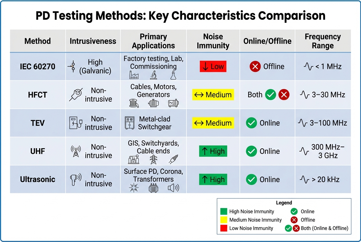
| Method | Intrusiveness | Primary Applications | Noise Immunity | Online/Offline | Frequency Range |
|---|---|---|---|---|---|
| IEC 60270 | High (Galvanic) | Factory testing, Lab, Commissioning | Low | Offline | < 1 MHz |
| HFCT | Non-intrusive | Cables, Motors, Generators | Medium | Both | 3–30 MHz |
| TEV | Non-intrusive | Metal-clad Switchgear | Medium | Online | 3–100 MHz |
| UHF | Non-intrusive | GIS, Switchyards, Cable ends | High | Online | 300 MHz–3 GHz |
| Ultrasonic | Non-intrusive | Surface PD, Corona, Transformers | High | Online | > 20 kHz |
This table highlights the trade-offs between the methods, helping you determine which approach best fits your operational needs and testing environment.
Conclusion
Partial discharge (PD) testing plays a crucial role in preventing failures in high-voltage equipment. David Stewart, Marketing Manager at Electrom Instruments, emphasizes this point:
"PD is one of the major contributors to the degradation and failure of insulation systems in all rotating equipment."
Different testing methods are designed for specific needs. For instance, IEC 60270 is perfect for controlled environments, while non-intrusive techniques are better suited for online monitoring. The choice of method depends on your equipment and operational limitations. For metal-clad switchgear, TEV sensors are highly effective at detecting internal PD. On the other hand, UHF methods are preferred for Gas Insulated Switchgear (GIS) because they offer excellent noise immunity. If you're dealing with cables or need to monitor large facilities, HFCT sensors provide the advantage of detecting PD sources from hundreds of meters away. A well-thought-out monitoring plan that integrates these methods can yield the best results.
To enhance detection, baseline testing during commissioning should be paired with regular trending. Single measurements may not reveal much; instead, tracking changes in PD magnitude and RPDIV over time is key to spotting insulation degradation. For critical assets where downtime is not an option, continuous 24/7 monitoring with automated alerts is a smart choice.
Consistency in measurement techniques is essential since different methods aren't directly comparable. Using a combination of sensors - like pairing TEV for internal PD with ultrasonic tools for surface discharges - provides comprehensive coverage. This proactive strategy shifts maintenance from being reactive to proactive, helping to extend the lifespan of your equipment and avoiding costly, unexpected outages.
FAQs
What are the benefits of non-intrusive partial discharge (PD) testing compared to the IEC 60270 method?
Non-intrusive partial discharge (PD) testing methods bring a level of convenience and efficiency that sets them apart from the IEC 60270 standard. These techniques enable real-time monitoring of equipment insulation without the need for shutdowns or disconnections. The result? Less downtime and lower maintenance costs. Plus, because they’re less invasive, there’s a reduced risk of causing damage during testing, and potential issues can be identified early - before they turn into bigger problems.
On the other hand, the IEC 60270 method, while known for its precision and reliability in controlled or lab settings, often requires equipment to be taken offline or placed under specific test conditions. This can lead to interruptions in operations and increased maintenance expenses. In contrast, non-intrusive methods allow for continuous, on-site monitoring, making it possible to assess equipment health without disrupting day-to-day activities.
What makes the UHF method effective at reducing noise in partial discharge (PD) testing?
The UHF method stands out as an effective approach for minimizing noise during partial discharge (PD) testing. It works by detecting electromagnetic waves within the ultra-high frequency (UHF) range, which are inherently less susceptible to interference from external electrical noise. This ensures a cleaner and more accurate detection of PD activity.
By targeting UHF signals, this technique helps technicians separate actual PD signals from background interference. This makes it a dependable solution for testing high-voltage equipment, even in environments prone to significant electrical disturbances.
Why is it important to use multiple methods for partial discharge testing?
Using several approaches for partial discharge (PD) testing provides a more thorough and precise assessment of high-voltage equipment. Each method is tailored to detect specific types of PD activity, such as internal discharges, surface discharges, or corona effects, which can occur in different areas of the equipment. Combining these techniques ensures that potential problems are less likely to go unnoticed.
This approach enhances both sensitivity and reliability, making it easier to spot early signs of insulation deterioration or damage. Identifying these issues early helps prevent unexpected breakdowns, prolongs the equipment's service life, and enables proactive maintenance to maintain smooth operations.


