
Grounding vs. Bonding in Solar Systems
Grounding and bonding are essential for solar system safety and compliance. Grounding connects the system to the earth, stabilizing voltage and protecting against surges like lightning strikes. Bonding links all metal components, ensuring they share the same electrical potential and providing a clear path for fault currents to trip protective devices. Both are critical to avoid electrical hazards, inspection failures, and system damage.
Key Points:
- Grounding: Stabilizes voltage and dissipates surge energy.
- Bonding: Ensures metal parts are electrically connected and clears faults.
- Common Issues: Improper grounding causes 53% of inspection failures; anodized aluminum frames often fail bonding tests without proper hardware.
- Hardware: Use UL 2703-listed clips for bonding and NEC-compliant conductors for grounding.
Understanding these practices ensures safer installations and smoother inspections.
What is Grounding and Bonding on a Solar PV System?
Grounding in Solar Systems
Grounding connects your solar system - or its equipment - to the earth, serving two key purposes: creating a stable voltage reference and providing a safe path for fault current. These roles are crucial for an effective and safe installation.
System Grounding vs. Equipment Grounding
System grounding involves connecting a current-carrying conductor to the earth. This stabilizes the system's voltage and provides a low-resistance path to dissipate energy from lightning strikes or voltage surges. On the other hand, equipment grounding ensures all non-current-carrying metal parts (like module frames, racking, enclosures, and conduit) are bonded to a grounding conductor. This setup offers a clear path for fault current, reducing potential hazards.
As Rainer Neumann, Content Head at SurgePV, points out:
"The GEC cannot serve as the EGC, and the EGC cannot serve as the GEC. They are different conductors, sized by different tables, serving different functions."
The sizing of these conductors is critical. The EGC is sized according to NEC Table 250.122, based on the OCPD rating, while the GEC is sized using Table 250.66 (for AC) or Table 250.166 (for DC). Additionally, the GEC must always be copper to avoid corrosion issues. Notably, over 90% of modern U.S. residential solar installations use functionally grounded systems. These setups rely on transformerless inverters that digitally monitor insulation resistance to establish an electronic ground reference.
What Grounding Does in Solar PV
The EGC primarily enhances safety by protecting personnel. For example, if a fault occurs - such as a wire touching a metal enclosure - the EGC rapidly directs the fault current back to the source. This action trips the OCPD, reducing the risk of electric shock. Meanwhile, system grounding stabilizes voltage and shields the system from surges. The earth acts as a sink, absorbing transient energy from lightning strikes or accidental contact with high-voltage lines. Together, these grounding methods are essential for protecting both the system and individuals during faults.
Main Grounding Components in Solar Systems
To ensure effective grounding, selecting the right components is critical. A properly grounded solar system relies on three main components:
- Grounding electrode: Examples include ground rods or concrete-encased rebar.
- Grounding electrode conductor (GEC): Connects the system to the grounding electrode.
- Equipment grounding conductor (EGC): Runs from the array back to the source.
One challenge in solar installations is maintaining electrical continuity across module frames. The anodized oxide layer on these frames can prevent standard bolts from creating a proper connection. To address this, UL 2703-listed hardware, like WEEB clips, is required to breach the anodized coating. Using unlisted star washers can lead to failed continuity inspections .
For sizing the EGC, refer to NEC Table 250.122. Here’s a quick guide:
| OCPD Rating | EGC Size (AWG Copper) | Typical Application |
|---|---|---|
| 15 A | 14 AWG | Microinverter or DC optimizer branch |
| 20 A | 12 AWG | String circuit with module-level protection |
| 30–60 A | 10 AWG | Residential homerun or combiner output |
| 100 A | 8 AWG | Large residential or commercial combiner |
For the GEC, a minimum of 6 AWG bare solid copper is required. Ensure gradual bends (at least an 8-inch radius) and avoid direct contact between bare copper and aluminum rails. Use stainless steel separators or tin-plated lugs to prevent galvanic corrosion .
Bonding in Solar Systems
What Bonding Does and Why It Matters
Bonding connects all exposed metal parts - like frames, rails, and enclosures - ensuring they share the same electrical potential. This minimizes the risk of electrical shock and creates a reliable fault-current path for overcurrent protection devices (OCPDs).
As Mike Holt, NEC Consultant, explains:
"The main purpose of bonding is to remove dangerous voltage from metallic objects so undesired current cannot flow between them."
Beyond preventing shocks, bonding is essential for establishing a low-impedance fault-current path. This path allows OCPDs to function properly by providing a fast and clear route for fault current to return to the source and trip the breaker. Importantly, the earth itself cannot serve as this path - NEC 250.4(A) explicitly states it is not a suitable ground-fault current pathway. With this in mind, it’s crucial to identify and bond all necessary components to ensure a continuous and effective connection.
Components That Require Bonding in Solar PV
According to NEC 690.43, all exposed metal parts must be bonded. This includes PV module frames, racking rails, conduit, combiner boxes, inverter chassis, DC-to-DC converter enclosures, and junction boxes. Missing even one of these components can disrupt the fault-current pathway, creating potential hazards.
Data from the Massachusetts DOER highlights the risks: 18% of critical solar violations occur at the array, and 16% at the inverter, often due to improper bonding. These failures can lead to energized metal surfaces or even fires. To prevent such issues, continuous bonding pathways must be established using specialized methods.
Common Bonding Methods
One of the biggest challenges in solar bonding is dealing with anodized aluminum, commonly used in module frames and rails. The oxide layer on anodized aluminum is non-conductive, so standard bolts or star washers often fail to create a reliable bond. As Rainer Neumann, Content Head at SurgePV, points out:
"The most common inspection failure: an ungrounded array frame caused by assuming a bolted rail connection provides continuity through anodized aluminum."
To ensure proper bonding, use UL 2703-listed hardware with hardened pins designed to pierce the anodized coating. WEEB (Washer Electrical Equipment Bond) clips are a popular choice, but they are single-use components. Repositioning or retorquing them voids their listing and compromises the bond. Always follow the manufacturer’s torque specifications using a calibrated torque screwdriver, as loose connections can lead to high-resistance faults and inspection failures.
For areas prone to movement or thermal expansion - like solar trackers or long rail runs - braided copper bonding jumpers are essential. These flexible connectors maintain electrical continuity even through temperature changes that could otherwise break rigid conductors. Additionally, when copper and aluminum come into contact, use tin-plated or stainless steel hardware to prevent galvanic corrosion over the system’s 25-year lifespan.
sbb-itb-501186b
Grounding vs. Bonding: Differences and How They Work Together
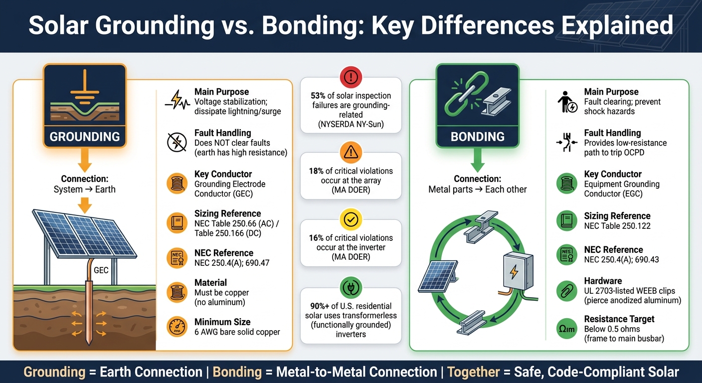
Solar Grounding vs. Bonding: Key Differences Explained
How Grounding and Bonding Differ
Grounding and bonding serve distinct but complementary roles in electrical systems. Here's the difference: grounding connects the system to the earth, while bonding ensures all metal components are electrically connected to each other.
Grounding helps stabilize voltage levels and provides a path to dissipate energy from events like lightning strikes or power surges. Bonding, on the other hand, ensures all exposed metal parts - such as frames, rails, and enclosures - are at the same electrical potential. This creates a low-resistance path for fault currents, which is critical for protecting people and equipment.
One common misunderstanding, especially in solar installations, is thinking a ground rod clears electrical faults. It doesn’t. The earth’s resistance is far too high to trip a breaker. Fault clearance is bonding's job, not grounding's.
How They Interact During a Fault
When a fault occurs - such as a live conductor coming into contact with a metal component - bonding provides the low-resistance path needed to trip the protective device. Grounding, meanwhile, stabilizes the system's voltage by maintaining a consistent reference point.
"Bonding is what actually protects people from electrocution during a ground fault - it provides the effective ground-fault current path." - SparkShift
In ungrounded photovoltaic (PV) arrays, bonding takes on an even greater role. Without a grounded DC conductor, the system relies entirely on the bonded metal pathway for the inverter’s ground-fault detection system to identify and isolate faults .
Comparison Table
| Feature | Grounding | Bonding |
|---|---|---|
| Connection | System to Earth | Metal parts to each other |
| Main Purpose | Voltage stabilization; dissipate lightning/surge energy | Fault clearing; prevent shock hazards |
| Fault Handling | Does not clear faults (earth has high resistance) | Provides a low-resistance path to trip OCPD |
| Key Conductor | Grounding Electrode Conductor (GEC) | Equipment Grounding Conductor (EGC) |
| Sizing Reference | NEC Table 250.66 | NEC Table 250.122 |
| NEC Reference | NEC 250.4(A); 690.47 | NEC 250.4(A); 690.43 |
This side-by-side comparison highlights why both grounding and bonding are essential for proper fault management and overall system safety.
To ensure the bonding system is functioning correctly before activating the system, use a low-resistance ohmmeter. Test the connection between the furthest module frame and the main grounding busbar. The resistance should measure below 0.5 ohms. If it’s higher, there’s likely a break in the fault-current path that needs to be fixed before the system is operational.
Practical Applications and Equipment Selection
How Grounding and Bonding Affect Solar System Design
The first decision that influences the entire solar system design is inverter topology. In the U.S., most residential installations now use transformerless inverters. This choice matters because transformerless systems require the DC array to remain ungrounded, meaning both poles must be switched and protected. This setup contrasts with older transformer-isolated systems, where one DC conductor was grounded through a Ground-Fault Detector Interrupter (GFDI) fuse.
Another key factor is conduit routing. Equipment Grounding Conductors (EGCs) must share the same raceway as the circuit conductors. Placing them in separate conduits can create inductive ground loops, which often lead to nuisance tripping of Arc-Fault Circuit Interrupters (AFCIs) or Ground-Fault Circuit Interrupters (GFCIs). For photovoltaic (PV) circuits, the National Electrical Code (NEC) mandates that EGCs run inside metallic raceways - such as Rigid Metal Conduit (RMC), Intermediate Metal Conduit (IMC), or Electrical Metallic Tubing (EMT) - from the array to the first disconnect point.
Grounding electrode placement also plays a role in layout planning. While roof-mounted arrays typically don’t require a dedicated grounding electrode, ground-mounted arrays located more than 6 feet from a building do. If bedrock obstructs the installation of an 8-foot grounding rod, the NEC permits burying the rod horizontally in a trench at least 30 inches deep.
"Grounding is the most frequently failed category in solar PV inspections." - Rainer Neumann, Content Head, SurgePV
Grounding issues are a significant problem, showing up in 53% of solar systems inspected under the NYSERDA NY-Sun program. These deficiencies are the leading cause of permit re-inspections and delays in receiving Permission to Operate (PTO).
With these design principles in mind, let’s explore the hardware that ensures proper grounding and bonding.
Equipment Needed for Grounding and Bonding
Selecting the right hardware is critical for meeting grounding and bonding requirements. Here’s an overview of the essential components:
- Grounding Electrode Conductors (GEC): These must be copper, as aluminum is not allowed due to its susceptibility to corrosion in buried connections. The minimum size is 8 AWG copper, though many systems now require 6 AWG under NEC 2026 standards.
- Equipment Grounding Conductors (EGCs): These can be copper or aluminum and are sized based on the Overcurrent Protection Device (OCPD) rating, as outlined in NEC Table 250.122. For example, a 15A microinverter branch requires 14 AWG copper, while a 100A combiner output needs 8 AWG copper. EGCs smaller than 6 AWG must be installed in conduit for physical protection.
- Bonding Anodized Aluminum Frames: Anodized coatings are non-conductive, so standard bolts won’t work. Use WEEB (Washer Electrical Equipment Bond) clips or UL 2703-listed clamps, which pierce the oxide layer to create a proper connection. Note that WEEB clips are single-use, and retorquing them invalidates their listing.
- Copper-to-Aluminum Connections: Direct contact between copper and aluminum can cause galvanic corrosion, leading to failure within 2–5 years. Use tin-plated copper lugs or specialized aluminum alloy lugs to prevent this issue.
- Surge Protective Devices (SPDs): Lightning protection is essential. SPDs are now required under NEC 2026 for legally required standby systems and are strongly recommended for rooftop arrays. A standard 6 AWG grounding wire cannot handle the immense energy of a direct lightning strike, which can reach 300 million volts and 30,000 amps.
For sourcing these components, platforms like Electrical Trader offer a range of new and used electrical equipment, including breakers, transformers, and other solar-specific components.
With the hardware in place, the next step is integrating these elements into the building’s electrical system.
Connecting PV Grounding and Bonding to Broader Electrical Systems
Grounding and bonding for PV systems must integrate seamlessly with the building’s electrical infrastructure. The PV system’s Equipment Grounding Conductor ties into the main service panel’s grounding busbar, which connects to the building’s grounding electrode system. This setup ensures a continuous, low-impedance fault path from the array to the electrical source.
It’s crucial to distinguish between the GEC and EGC, as these serve different purposes. The GEC provides the earth reference and lightning path, while the EGC handles fault clearance. Confusing the two - or assuming one conductor can perform both roles - violates code and creates safety risks.
For systems with battery storage or backup loads, grounding and bonding requirements extend to components like the battery enclosure, transfer switch, and any sub-panels fed by the inverter. Each enclosure must connect to the EGC, and the system must maintain a single grounding point to avoid ground loops. Data from Massachusetts DOER highlights that 18% of critical violations occur at the array and 16% at the inverter, often due to grounding errors. This underscores the importance of carefully managing the connection points between subsystems.
Conclusion: Why Grounding and Bonding Are Central to Solar Safety
Grounding and bonding work hand-in-hand to ensure the safety and reliability of solar installations. Grounding stabilizes voltage by providing a safe path for lightning surges to dissipate into the earth. Bonding, on the other hand, connects all metal surfaces into a unified, low-resistance circuit, ensuring faults are quickly cleared. Together, they form the backbone of a safe and compliant solar setup, helping installers meet NEC standards and avoid common inspection issues.
When grounding or bonding is faulty, the risks are immediate and dangerous. A missing or corroded bond can leave metal components energized, creating a hidden shock hazard. Similarly, inadequate grounding can expose inverter electronics to damaging surges or allow a ground fault to arc continuously instead of clearing as designed.
As Solar Permit Solutions aptly states:
"The moment an electrical fault develops is not the time to discover that safety circuits are inadequate."
Grounding ties the system securely to the earth, while bonding ensures all metal parts maintain the same electrical potential. This interconnectedness is why NEC Article 690 treats them as a unified requirement rather than separate tasks.
To ensure long-term safety, follow these key practices: confirm continuity from the furthest module to the main busbar (aim for resistance below 0.5 ohms) and use only UL 2703- or UL 467-listed hardware. These simple steps, taken during installation, can save significant time and prevent costly or dangerous failures down the road.
FAQs
Do I need both a GEC and an EGC in a PV system?
Yes, an Equipment Grounding Conductor (EGC) is required for photovoltaic (PV) systems. However, a separate Grounding Electrode Conductor (GEC) isn't always mandatory for the PV array.
The EGC plays a critical role by bonding all non-current-carrying metal parts of the system. This ensures that, in the event of a fault, enough current flows to trip the overcurrent protection devices. On the other hand, the GEC is responsible for connecting the system to the earth, providing stability and protection against lightning. In many residential systems, the building's existing grounding setup can serve this purpose, eliminating the need for a dedicated GEC for the PV array.
Why doesn’t a ground rod trip a breaker during a fault?
A ground rod alone can’t trip a breaker because the earth has too much electrical resistance to let enough fault current flow back to the power source. Breakers need a high-amperage, low-resistance path to activate. Since the earth’s resistance is generally too high, systems rely on dedicated metallic conductors to create a low-resistance circuit, ensuring proper safety and functionality.
What’s the best way to bond anodized aluminum module frames?
The most effective way to connect anodized aluminum module frames is by using UL 2703-listed hardware, including bonding washers, grounding clips, or integrated racking clips. These components feature sharp teeth or serrations designed to penetrate the anodized coating, ensuring a secure, gas-tight metal-to-metal connection. Steer clear of outdated techniques like drilling holes for lugs, as they can lead to poor connections and potential corrosion issues. Always check that the hardware is compatible with your racking system.


