
Grounding and Bonding Per NEC 2026
Grounding and bonding are central to electrical safety, and the 2026 NEC introduces key updates to improve clarity and compliance. Grounding connects electrical systems to the earth to manage voltage surges, while bonding ensures metal parts are linked to create a fault path, enabling protective devices to trip quickly. The 2026 NEC reorganizes Article 250 to focus on systems operating at 1,000 volts AC or less (or 1,500 volts DC or less), with higher-voltage requirements moved to a new Article 270.
Key highlights include:
- Grounding Systems: Clear guidelines for grounded and ungrounded AC systems, including electrode requirements and fault-current path rules.
- Equipment Grounding Conductors (EGCs): Updated sizing based on overcurrent protection device ratings and stricter voltage limits for certain materials.
- Service Bonding: Enhanced standards for bonding jumpers and terminations to ensure system integrity.
- Emerging Technologies: Adjustments for electric vehicle equipment and energy management systems.
These updates simplify compliance for electricians and improve safety by addressing modern electrical challenges.
100 Days of the 2026 NEC Changes Day 32: 250.122 Sizing Equipment Grounding Conductors.
sbb-itb-501186b
NEC 2026 Article 250: Purpose and Requirements
Article 250 outlines the grounding and bonding practices essential for electrical installations. The 2026 edition refines its scope by limiting Article 250 to systems operating under 1,000 V AC or 1,500 V DC. Requirements for higher-voltage systems have been shifted to the newly established Article 270, streamlining the Code for residential and commercial settings. This restructuring also supports the introduction of measurable performance criteria detailed in Section 250.4.
Section 250.4 sets clear performance benchmarks for grounding and bonding. These aren't just procedural guidelines - they define the expected safety outcomes for electrical systems, equipment, and conductive materials.
Safety and Performance Goals
Grounding and bonding serve as the foundation for electrical safety, addressing both external threats and internal faults. Grounding helps stabilize voltage to earth during normal operations, which extends the lifespan of motors, transformers, and other equipment. It also limits sudden voltage spikes caused by lightning, power surges, or accidental contact with higher-voltage conductors. Without proper grounding, these transient voltages can cause equipment damage and increase the risk of fire.
Bonding, on the other hand, ensures that metal components maintain the same electrical potential, eliminating dangerous voltage differences. NEC consultant Mike Holt explains it well:
"Bonding is a metallic, low-impedance path between metallic objects. It puts metal parts at the same potential, thus eliminating a dangerous flow of current between them."
In the event of a ground fault, a well-bonded path ensures that fault current is quickly returned, allowing breakers to trip effectively. The speed at which this happens depends on maintaining low impedance. For instance, a 20-amp breaker with a 40-amp overload might take 25 to 150 seconds to trip, but at 100 amps (five times its rating), it trips within 5 to 20 seconds. This rapid response is critical for minimizing hazards.
Article 250 Compliance Standards
The 2026 NEC highlights the importance of establishing an effective ground-fault current path (EGFCP) - a low-impedance route that reliably returns fault current to trip protective devices. Relying solely on the earth for this purpose is ineffective due to its high resistance.
Another key compliance element involves ensuring that conductors meet tested voltage limits. The 2026 edition introduces specific voltage restrictions for equipment grounding conductors (EGCs) to align with product testing standards. For example, the armor of Type AC cable or the copper sheath of Type MI cable, when used as an EGC, cannot exceed 600 volts nominal circuit voltage. Similarly, flexible metallic tubing is capped at 1,000 volts. These specifications ensure that wiring methods operate safely, preventing situations where metal enclosures could remain energized during faults.
The Code also addresses static drainage to reduce the risk of flashovers in hazardous environments. Combined with rapid fault clearing to prevent fires, these standards work together to safeguard both people and property from electrical dangers.
Grounding System Requirements
NEC 2026 Grounding Electrode System Requirements and Specifications
The 2026 NEC lays out clear guidelines for grounding systems, ensuring installations meet safety standards. It distinguishes between grounded and ungrounded AC systems, each with tailored requirements to protect both people and equipment.
Grounded AC Systems (250.20)
In the U.S., most AC systems are grounded. This means one conductor is intentionally connected to the earth to manage voltage spikes from lightning, power surges, or accidental high-voltage contact, while also stabilizing voltage during normal operation. According to Section 250.24(D), the equipment grounding conductors, service-equipment enclosures, and the grounded service conductor must all connect to the grounding electrode system. This creates a unified system that keeps everything at earth potential.
However, the earth itself cannot serve as the fault-current path. Instead, metal parts must be bonded together to form a permanent, low-impedance path back to the power source. This ensures that in the event of a fault, enough current flows to trip the breaker quickly, minimizing potential hazards.
Ungrounded AC Systems (250.21)
Ungrounded systems, where no conductor is intentionally connected to the earth, are typically used in facilities that require uninterrupted power, such as assembly lines or continuous operations. These systems allow a single ground fault to occur without disrupting power, avoiding costly shutdowns. However, they must include ground-fault detection equipment installed near the supply source to monitor for the first phase-to-ground fault (250.21(B)).
Additionally, ungrounded systems require specific labeling. Enclosures must display a durable label stating: "Caution: Ungrounded System Operating - ____ Volts" (250.21(C)). Michael Johnston, a former NECA executive, explains:
"The requirement for ground detection provides the ability to monitor ungrounded systems to detect a first phase-to-ground fault on the system".
If a fault is detected, qualified personnel must act immediately. A second fault on a different phase before clearing the first can lead to a phase-to-phase short circuit, potentially causing severe equipment damage.
Grounding Electrode Systems (250.52)
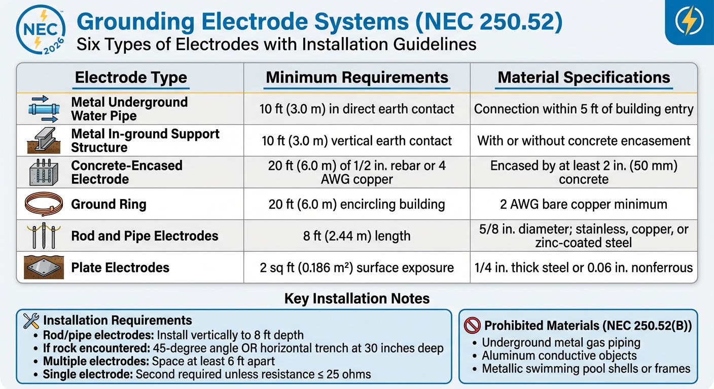
A compliant grounding electrode system bonds together all available electrodes at a building or structure, as required by Section 250.50. The 2026 NEC identifies six types of electrodes, each with specific installation guidelines:
| Electrode Type | Minimum Requirements | Material Specifications |
|---|---|---|
| Metal Underground Water Pipe | 10 ft (3.0 m) in direct earth contact | Connection within 5 ft of building entry |
| Metal In-ground Support Structure | 10 ft (3.0 m) vertical earth contact | With or without concrete encasement |
| Concrete-Encased Electrode | 20 ft (6.0 m) of 1/2 in. rebar or 4 AWG copper | Encased by at least 2 in. (50 mm) concrete |
| Ground Ring | 20 ft (6.0 m) encircling building | 2 AWG bare copper minimum |
| Rod and Pipe Electrodes | 8 ft (2.44 m) length | 5/8 in. diameter; stainless, copper, or zinc-coated steel |
| Plate Electrodes | 2 sq ft (0.186 m²) surface exposure | 1/4 in. thick steel or 0.06 in. nonferrous |
Joseph Wages, Jr., Director of Digital Education at IAEI, emphasizes:
"The primary purpose of the grounding electrode(s) is to maintain the electrical equipment at the earth's potential present where the grounding electrode(s) is located. The earth's potential is assumed to be zero".
When installing rod or pipe electrodes, they should be driven vertically to a depth of 8 ft. If rock is encountered, they can be installed at a 45-degree angle or buried horizontally in a trench at least 30 inches deep. For a single rod, pipe, or plate electrode, a second electrode is required unless the first demonstrates a resistance to earth of 25 ohms or less. If multiple electrodes are used, they must be spaced at least 6 ft apart.
Proper installation of electrodes ensures a consistent earth potential, which is crucial for efficient fault-clearing. The Code explicitly prohibits certain materials from being used as grounding electrodes, including underground metal gas piping, aluminum conductive objects, and metallic swimming pool shells or frames (250.52(B)). These materials either present safety concerns or lack the durability needed for reliable grounding.
These electrode requirements are fundamental for creating effective fault current paths, which are further detailed in subsequent equipment grounding standards.
Equipment Grounding and Bonding Practices
Building on the established grounding electrode system, the following practices outline how to properly install equipment grounding and bonding components. These steps are essential for meeting NEC 2026 performance standards and ensuring electrical safety. Once the grounding electrode system is set up, the next priority is making sure equipment grounding conductors (EGCs) and bonding jumpers are correctly sized, installed, and connected. These components form the low-impedance fault current path that allows overcurrent protective devices (OCPDs) to quickly interrupt fault currents, protecting both people and equipment.
Sizing Equipment Grounding Conductors (Table 250.122)
The NEC 2026 Table 250.122 determines the minimum size of an EGC based on the rating of the circuit's OCPD - not the ampacity of the circuit conductors or the connected load. To size an EGC, find the circuit breaker or fuse rating in the left-hand column of Table 250.122. If the exact rating isn’t listed, use the next higher rating.
For example:
- A 20-ampere circuit requires a minimum 12 AWG copper EGC.
- A 100-ampere circuit requires 8 AWG copper.
If ungrounded conductors are upsized to reduce voltage drop, the EGC must also be increased proportionally based on the circular mil area (per 250.122(B)). However, the EGC is never required to be larger than the ungrounded conductors supplying the equipment. For parallel installations, each raceway must include a full-sized EGC based on the OCPD rating. When multiple circuits share a raceway, a single EGC can be used, provided it’s sized for the largest OCPD protecting any circuit. For motor circuits, the EGC size depends on the branch-circuit short-circuit and ground-fault protective device rating, not the motor’s full-load amperage.
After sizing, proper installation is key to maintaining an effective conductive path.
Installation Practices (250.120, 250.130)
Proper installation ensures a continuous low-impedance path. Any nonconductive coatings like paint, lacquer, or enamel must be removed from threads and contact surfaces unless the fittings are designed to bypass this step.
The 2026 NEC specifies that threaded conduits entering enclosures without female threads must have a locknut or fitting on both sides of the enclosure (342.29 & 344.29) to maintain mechanical and electrical integrity. Welding metal raceways for connection or support is not allowed, as welds are hard to verify and may damage conductors.
For electronic equipment prone to electromagnetic interference, isolated grounding is an option (250.96(B)). This method uses listed nonmetallic raceway fittings to break the continuity of metal parts, while an insulated EGC inside the raceway ensures safety grounding.
Service Equipment Bonding (250.92, 250.96)
Service equipment bonding is a critical part of maintaining system integrity. It ensures all metal enclosures and noncurrent-carrying parts are effectively connected to the grounded service conductor. Supply-side bonding jumpers - those installed on the line side of the main OCPD - must be sized according to Table 250.102(C). For ungrounded supply conductors larger than those listed in the table, the bonding jumper must have an area of at least 12.5% of the largest ungrounded conductor. For instance, a parallel set of 1,200 kcmil copper conductors would require a bonding jumper with at least 150 kcmil (commonly 3/0 AWG).
Additionally, all noncurrent-carrying metal parts used as EGCs must be effectively connected, as outlined in 250.96. As Mike Holt explains:
"Electricity does not choose 'the path of least resistance,' but flows on all paths presented to it. The flow divides among those paths in inverse proportion to their impedances".
To reduce impedance and avoid dangerous "side flashes" during lightning events, grounding electrode conductors and bonding jumpers should be kept as short as possible, avoiding unnecessary loops. This setup ensures fault currents flow efficiently back to the source, allowing OCPDs to function as designed.
Changes in NEC 2026 Grounding and Bonding
The 2026 National Electrical Code (NEC) introduces updates to Article 250, reshaping how grounding and bonding are handled. These changes emphasize the distinction between low-voltage and high-voltage systems, with additional updates to terminal and connection standards aimed at improving safety and compliance.
Grounding Over 1000 Volts Relocated
One major change is the relocation of grounding and bonding requirements for systems above 1,000 V AC or 1,500 V DC. Previously housed in Article 250 (Part 10), these rules now reside in a new standalone Article 270. This adjustment separates high-voltage requirements from those for systems under 1,000 volts AC or 1,500 volts DC. Related provisions in Articles 265, 266, 267, and 268 have also been updated to align with this shift.
By isolating high-voltage rules, the NEC simplifies code navigation for electricians and inspectors. Article 250 now exclusively covers installations within the lower voltage range, while Article 270 provides detailed guidance for higher-voltage systems. Electricians and designers working with high-voltage installations must refer to Article 270 for grounding and bonding protocols.
Couplings and Connectors Updates
The NEC has also refined its requirements for couplings and connectors. Section 250.8(A) now explicitly includes "grounding and bonding terminations" among the items requiring one of eight approved connection methods. This ensures that devices like lugs or terminal bars meet the same standards as the conductor connections. Electricians must confirm that the securing method complies with these approved practices, such as ensuring a lug or terminal bar is firmly and correctly installed.
Additionally, Section 250.118 introduces specific voltage limits for wiring methods used as equipment grounding conductors (EGCs). For instance, Type AC cable armor and Type MI cable copper sheaths are now restricted to circuits not exceeding 600 volts when used as EGCs, while flexible metallic tubing is limited to circuits of up to 1,000 volts. Installers must verify the circuit voltage before using these materials as EGCs to ensure compliance with the updated standards.
Conclusion
The NEC 2026 grounding and bonding standards play a critical role in electrical safety by protecting against shocks, stabilizing voltage, and ensuring faults are cleared quickly. With updates like moving high-voltage requirements to Article 270 and clarifying termination standards in Section 250.8(A), the code is now more straightforward for electricians working with various voltage ranges. These changes emphasize the importance of system grounding, proper electrode installation, and effective bonding practices.
"The safety of the building or structure depends on you." - Joseph Wages, Jr., Director of Digital Education, IAEI
It's essential to verify that all components comply with listing and manufacturer specifications, as Section 110.3(B) prohibits installations that conflict with provided instructions. Many manufacturers now include QR codes for quick access to guidelines, making it easier to ensure compliance. Starting with the right equipment saves time and avoids costly rework, while also ensuring that grounding electrode conductors, bonding jumpers, and terminal connections meet the stringent standards needed for safe operation.
Consider the risks: arc flash events can reach temperatures as high as 35,000°F. For instance, a 120V fault through a 25Ω ground results in just 4.80A - far too low to trip a standard breaker - leaving the equipment dangerously energized. Proper bonding addresses these hazards by creating a permanent, low-impedance path to safely redirect fault currents.
These updates not only improve safety but also simplify sourcing and installation processes. For professionals looking for compliant components, platforms like Electrical Trader offer a wide range of listed breakers, transformers, grounding equipment, and power distribution tools that align with current code requirements. Staying up to date with NEC changes and using approved materials ensures installations are safe, dependable, and inspection-ready.
FAQs
What moved from NEC 250 to the new Article 270?
The requirements for grounding and bonding in systems exceeding 1000 volts AC and 1500 volts DC have been moved from NEC 250 to the newly introduced Article 270 in the 2026 NEC. This change aims to streamline the code and provide a clearer focus on high-voltage system standards.
When do I need two ground rods instead of one?
To meet NEC grounding and bonding standards, two ground rods are necessary if the first rod fails to achieve a contact resistance of 25 ohms or less. When installing the supplemental rod, make sure it is placed at least 6 feet away from the first rod to ensure proper compliance.
How do I size an equipment grounding conductor in NEC 2026?
To determine the correct size for an equipment grounding conductor (EGC) under NEC 2026 guidelines, you’ll need to refer to the overcurrent protective device (OCPD) rating. Specifically, Article 250.122 provides the necessary details, and Table 250.122 will help you match the EGC size to the OCPD rating.
It’s important to note that the sizing process for an EGC is not the same as for a grounding electrode conductor (GEC). The GEC size is determined using Table 250.66, which is based on the size of the service-entrance conductors. Always ensure you're consulting the most up-to-date NEC standards for compliance.
Related Blog Posts
- Top Standards for Medium-Voltage Grounding Systems
- Ultimate Guide to Grounding Residential Electrical Systems
- Common NEC Violations in Industrial Settings
- NEC Requirements for Transformer Grounding Electrode Systems


