NEC Requirements for Transformer Grounding Electrode Systems
Transformer grounding electrode systems are essential for safety, ensuring proper fault current paths and voltage stability. The National Electrical Code (NEC) outlines specific rules to prevent hazards like shock risks and equipment failure. Key points include:
- Grounding Electrode Systems: These create a low-impedance fault path, connecting transformers to approved electrodes like water pipes, ground rods, or concrete-encased electrodes.
- NEC Compliance: Following NEC standards prevents issues like undersized conductors or improper connections, which can lead to shock hazards or faults.
- Separately Derived Systems (SDS): Transformers classified as SDS must connect the grounding electrode conductor (GEC) to the neutral at the same point as the system bonding jumper.
- Outdoor Transformers: NEC 250.30(C) requires grounding at the outdoor source, with isolated neutral conductors to avoid parallel current paths.
- Sizing Conductors: Use NEC Tables 250.66 and 250.102(C)(1) to size grounding electrode conductors and system bonding jumpers correctly.
Proper installation and compliance with NEC guidelines ensure safety, prevent faults, and protect both people and equipment.
Grounding, Transformers [250.30, 2020 NEC]
Grounding Requirements for Separately Derived Systems
Separately derived transformers must follow NEC grounding requirements to ensure safety. A separately derived system is defined as having no direct electrical connection to another system except through grounding and bonding. To meet these requirements, the grounding electrode conductor (GEC) must connect the grounded conductor (neutral) to the grounding electrode at the same point where the system bonding jumper is connected. This setup is crucial for preventing neutral current from flowing through metal components.
Mike Holt, a well-known NEC expert, emphasizes this point:
"To prevent objectionable neutral current from flowing onto metal parts, the grounding electrode conductor must originate at the same point on the separately derived system where the system bonding jumper is connected."
The grounding electrode should be as close as possible to the system bonding jumper's connection point. Preferred grounding electrodes include a metal water pipe within 5 feet of where it enters the building or the structural metal frame of the building. If neither option is available, alternatives like concrete-encased electrodes (at least 20 feet of 1/2-inch rod or 4 AWG conductor), ground rings (minimum 2 AWG, buried 30 inches deep), or ground rods (with 8 feet of soil contact) can be used. These grounding practices form the foundation for NEC's transformer installation guidelines.
NEC 250.30(A)(4) and (5) Guidelines
NEC 250.30(A)(4) and (5) provide specific instructions for connecting transformers to the building's grounding electrode system. The size of the grounding electrode conductor is determined using NEC Table 250.66, based on the largest ungrounded conductor in the derived system. For buildings with multiple separately derived systems, a common grounding electrode conductor can be used, provided it is at least 3/0 AWG copper or 250 kcmil aluminum. These rules ensure proper grounding for both indoor and outdoor transformer installations.
Outdoor Transformer Grounding Requirements (NEC 250.30(C))
NEC 250.30(C) outlines requirements for transformers installed outside the building or structure they serve. When the source of a separately derived system is located outdoors, the grounding electrode connection must be made at the outdoor source, following NEC 250.50. This connection helps stabilize system voltage while providing protection against lightning surges or accidental contact with higher-voltage lines.
If the system bonding jumper is installed at the outdoor transformer, the grounded conductor (neutral) must be isolated from the disconnecting means enclosure within the building. This prevents parallel paths for neutral current. Additionally, a supply-side bonding jumper must connect the equipment grounding bar in the building's disconnecting means back to the transformer, sized according to NEC Table 250.102(C)(1). To further prevent improper neutral current flow, using PVC or another nonmetallic raceway between the outdoor transformer and the building is recommended.
Approved Grounding Electrode Types (NEC 250.52)
NEC-Approved Grounding Electrodes
The National Electrical Code (NEC) 250.52 outlines six types of grounding electrodes for transformer installations. For metal underground water pipes, at least 10 feet of the pipe must be in direct contact with the earth, and connections should be made within the first 5 feet of where the pipe enters the building. Similarly, metal in-ground support structures, such as pilings or casings, must also maintain 10 feet of vertical contact with the earth.
Concrete-encased electrodes, often referred to as Ufer grounds, require 20 feet of either 1/2-inch reinforcing bars or a #4 AWG bare copper conductor encased in at least 2 inches of concrete. Ground rings, on the other hand, must consist of a bare copper conductor (minimum #2 AWG), spanning at least 20 feet around the building and buried at a depth of 30 inches.
For rod and pipe electrodes, the minimum length is 8 feet. Pipes must have a trade size of at least 3/4 inch, while rods need a minimum diameter of 5/8 inch. To prevent corrosion, steel or iron rods and pipes must be galvanized or coated with another protective metal layer. Plate electrodes must expose at least 2 square feet of surface area to the surrounding soil. Steel or iron plates must be at least 1/4 inch thick, while nonferrous plates should be a minimum of 0.06 inches thick.
Certain materials are explicitly prohibited for use as grounding electrodes, including underground metal gas piping, aluminum, and swimming pool reinforcing steel. If bedrock prevents the vertical installation of rods, they can be driven at angles of up to 45 degrees. If this is still not feasible, the rods may be buried horizontally in trenches at least 30 inches deep.
When Two Grounding Electrodes Are Required
If a single rod, pipe, or plate electrode has a resistance greater than 25 ohms, a second electrode must be installed as a supplement. However, the NEC now emphasizes installing two electrodes as the default approach, rather than waiting to test for the 25-ohm resistance threshold. Michael Johnston, former Executive Director of Codes and Standards at NECA, explains this shift:
"The NEC has been improved to require installation of two electrodes as the first priority, rather than installing the second when the 25-ohm resistance is exceeded."
When multiple rod, pipe, or plate electrodes are used, they must be spaced at least 6 feet apart to ensure proper effectiveness. Additionally, the supplemental electrode must be bonded to the initial grounding electrode. This bond can be made through the grounding electrode conductor, the service neutral conductor, a nonflexible metal service raceway, or the service-disconnect enclosure. If grounding electrode bonding jumpers are used to connect electrodes, they must be made of copper when located within 18 inches of the earth.
These guidelines for approved electrode types are essential for determining the correct sizing of grounding electrode conductors, as outlined in NEC Table 250.66.
Sizing Grounding Electrode Conductors (NEC 250.66)
NEC Grounding Electrode Conductor Sizing Guide for Transformers
Using NEC Table 250.66 for Sizing
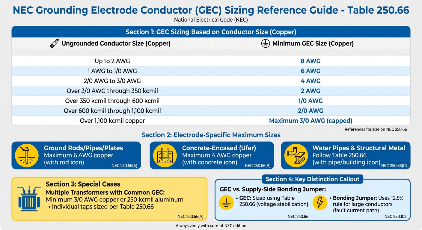
The size of the grounding electrode conductor (GEC) is determined by referring to NEC Table 250.66, which is based on the circular mil area of the largest ungrounded secondary conductor. Ensuring the GEC is correctly sized is essential for protecting equipment and enabling effective fault clearance. For transformers classified as separately derived systems, this involves calculating the circular mil area of the secondary phase conductors to determine the appropriate GEC size.
When dealing with parallel conductor sets, the combined cross-sectional area of all conductors is used. However, the maximum required size for a copper GEC is capped at 3/0 AWG, even if the derived phase conductors exceed 1,100 kcmil copper.
Some electrode types have specific maximum size limits, regardless of the conductor size. For example:
- GECs connected to ground rods, pipes, or plate electrodes don’t need to exceed 6 AWG copper.
- For concrete-encased electrodes (commonly known as Ufer grounds), the maximum required size is 4 AWG copper.
- Underground metal water pipes and in-ground structural metal must follow the sizing requirements in Table 250.66.
Mike Holt, from Mike Holt Enterprises, highlights the importance of proper termination:
"To prevent objectionable current from flowing onto metal parts of electrical equipment, as well as metal piping and structural steel, the grounding electrode conductor must terminate at the same point on the separately derived system where the system bonding jumper is installed."
For buildings with multiple transformers sharing a common GEC, the common conductor must be no smaller than 3/0 AWG copper or 250 kcmil aluminum. Individual taps to each transformer are then sized according to Table 250.66, based on the largest ungrounded secondary conductor for each transformer.
Once the GEC sizing is established, attention turns to the supply-side bonding jumpers, which follow their own set of rules.
Supply-Side Bonding Jumper Sizing
Sizing the supply-side bonding jumpers involves a different approach from the GEC. While the GEC is sized using Table 250.66, supply-side bonding jumpers must comply with NEC 250.30(A)(5) and the "12.5% rule" when ungrounded conductors exceed the sizes listed in the table. This distinction arises because bonding jumpers are part of the effective ground-fault current path, whereas the GEC is not.
Duke W. Schamel, P.E., from Electrical Service Solutions, Inc., explains the difference:
"Because the maximum current in a grounding electrode conductor is limited by the impedance path through the grounding electrode and earth - and is not intended to be part of the effective ground-fault current path - the 12.5% rule is not applicable."
The GEC primarily serves to stabilize voltage to ground and limit surges, such as those caused by lightning, rather than to carry ground-fault current under normal conditions.
sbb-itb-501186b
System Bonding Jumper Requirements (NEC 250.28)
Sizing Bonding Jumpers with NEC Table 250.102(C)(1)
The system bonding jumper (SBJ) plays a crucial role in electrical safety by connecting the grounded circuit conductor (neutral) to the supply-side bonding jumper or equipment grounding conductor in a separately derived system. Its size is determined using NEC Table 250.102(C)(1), based on the largest ungrounded secondary conductor. This ensures the SBJ provides a low-impedance fault path to activate overcurrent protection systems effectively.
Unlike the grounding electrode conductor, which is sized using Table 250.66, the SBJ is specifically designed to handle fault current. Here's a quick reference for SBJ sizing:
| Ungrounded Conductor Size (Copper) | Minimum System Bonding Jumper Size (Copper) |
|---|---|
| Up to 2 AWG | 8 AWG |
| 1 AWG to 1/0 AWG | 6 AWG |
| 2/0 AWG to 3/0 AWG | 4 AWG |
| Over 3/0 AWG through 350 kcmil | 2 AWG |
| Over 350 kcmil through 600 kcmil | 1/0 AWG |
| Over 600 kcmil through 1,100 kcmil | 2/0 AWG |
| Over 1,100 kcmil | 12.5% of conductor area |
For conductors larger than 1,100 kcmil copper or 1,750 kcmil aluminum, the 12.5% rule applies. This calculation is based on the total circular mil area of the conductor.
Proper installation is just as important as correct sizing. One critical consideration is avoiding parallel bonding paths, which can undermine system safety.
Avoiding Parallel Bonding Paths
Once the SBJ is sized correctly, its placement must be carefully thought out to ensure there are no unintended parallel current paths. The SBJ should only be installed at one location - this could be at the transformer, the first system disconnecting means, or somewhere in between. However, installing it at multiple points is a violation of NEC 250.6(A).
When parallel paths are created, normal return current can flow through the equipment grounding conductor instead of staying on the neutral. This can lead to energized metal enclosures and equipment. Worse, if the neutral conductor becomes disconnected while a parallel path exists, the equipment safety ground may become the sole return path. In such cases, all exposed metal parts could carry line voltage, posing severe shock hazards.
A real-world example highlights the dangers of improper bonding. In 2010, Electrical Service Solutions, Inc. conducted a national arc-flash hazard analysis at eight newly built distribution warehouses for a Global 100 company. Duke W. Schamel, P.E., uncovered over 35 NEC violations related to transformer bonding and grounding. These included missing or undersized system bonding jumpers and cases where jumpers were installed at multiple locations. Such errors compromised the ground-fault current path and created serious shock risks.
To comply with NEC 250.28, the SBJ must be made from a wire, bus, or screw, and it must not be spliced. This ensures a continuous and reliable connection.
Utility vs. Premises Transformers: Grounding Differences
Utility-Owned Transformers (NEC 250.24(A))
When a utility-owned transformer is located outside a building, an additional grounding connection is required. According to NEC 250.24(A), this involves connecting the grounded service conductor to a grounding electrode. This connection must be made either at the transformer itself or another approved exterior location. While NEC 90.2(B) exempts systems under exclusive utility control, NEC 250.24(A) ensures proper grounding for service conductors. This grounding stabilizes voltage to the earth and helps mitigate surges.
Mark C. Ode, the owner of Southwest Electrical Training and Consulting, emphasizes the importance of this grounding connection:
"The most important reason for the grounding electrode is to stabilize the voltage to earth during normal operation so that a zero reference is provided for the grounded neutral conductor."
"The grounding electrode also limits the voltage imposed by lightning, unintentional contact with higher-voltage lines and line voltage surges, helping to keep surge events from entering buildings."
Utilities typically specify the type of grounding electrode to use, with driven ground rods being a common choice. If the utility does not install the electrode, the responsibility falls to the electrical contractor.
On the other hand, premises-owned transformers follow a separate set of grounding rules.
Pad-Mounted Transformer Grounding
For premises-owned transformers, also called separately derived systems, the grounding requirements are outlined in NEC 250.30(C). Unlike utility-owned systems, the grounding electrode connection for these outdoor transformers must be made at the transformer's source. For pad-mounted installations, it’s essential to consult the utility's specification manual for details on pad configurations, the number of raceways, and the types of electrodes required. Common options include driven ground rods or concrete-encased electrodes, all of which comply with NEC 250.30(C).
A key design element for premises-owned transformers is isolating the grounded conductor (neutral) from the building’s disconnecting means enclosure. Using a nonmetallic raceway, such as PVC, ensures that the grounded conductor carries only neutral current, avoiding dangerous parallel paths. This approach enhances safety by eliminating potential hazards. Additionally, the supply-side bonding jumper must be sized according to NEC Table 250.102(C).
| Feature | Utility-Owned Transformer | Premises-Owned Transformer |
|---|---|---|
| NEC Section | 250.24(A) | 250.30(C) |
| Connection Location | At the transformer or any approved exterior point | At the source (transformer) only |
| Building Disconnect | Grounded conductor bonded to enclosure | Grounded conductor isolated from enclosure |
| Common Electrodes | Ground rods; butt-wrapped electrodes on poles | Ground rods; concrete-encased or structural metal electrodes |
Conclusion
Ensuring proper grounding and bonding in transformer installations is not just a regulatory requirement - it's a vital safety measure. These practices protect both people and equipment by creating effective fault current paths, stabilizing voltage levels, and shielding systems from lightning and electrical surges. By adhering to the guidelines set forth in the NEC, overcurrent protective devices can operate as intended, tripping instantly during faults and preventing hazardous shock risks.
However, compliance isn't always guaranteed. A nationwide arc-flash hazard analysis conducted at multiple warehouse sites uncovered over 35 NEC violations. These violations often remain hidden until a fault occurs, leading to breakers failing to trip and equipment staying energized. As industry experts warn, such oversights pose silent yet deadly risks.
Achieving compliance starts with understanding the key distinctions and proper sizing techniques for system components. Knowing how to differentiate between utility-owned and premises-owned transformers, correctly size system bonding jumpers, and install grounding electrode conductors are all critical steps for safe and compliant installations. Whether you’re working on a pad-mounted transformer or connecting to a utility service, avoiding parallel neutral current paths and ensuring secure electrode connections are essential for meeting safety and code requirements.
Selecting the right components is equally important for maintaining compliance. Electrical Trader offers a range of new and used components that meet industry standards, providing contractors and facility managers with reliable options for supporting safe, code-compliant installations while managing costs effectively.
FAQs
What does the NEC require for grounding separately derived systems in transformer installations?
The National Electrical Code (NEC) outlines specific requirements to ensure that a separately derived system, like a transformer, is grounded and bonded correctly for safety and compliance. Here's what this process involves:
- Installing a system bonding jumper that connects the secondary neutral to the equipment-grounding conductor. This should be done either at the source or at the first disconnect - but not both. The jumper must be sized according to Table 250.66 or Table 250.102(C).
- Running a grounding electrode conductor to an approved electrode, as detailed in sections 250.50 and 250.30(C).
- Verifying that there is no neutral-to-case connection on the load side, unless explicitly allowed under section 250.142(B).
Following these guidelines is essential to reduce electrical risks and maintain proper system performance in line with NEC standards.
How does the NEC determine the size of grounding electrode conductors for transformers?
When determining the size of the grounding electrode conductor for a transformer, the National Electrical Code (NEC) directs electricians to use Table 250.66. The size is calculated based on the largest ungrounded (phase) conductor supplying the transformer. If there are no service-entrance conductors present, the equivalent size of the largest ungrounded conductor is used instead.
This approach ensures the grounding system can safely carry fault currents, providing protection for both equipment and people.
Why is it critical to avoid parallel bonding paths in transformer grounding systems?
Avoiding parallel bonding paths is crucial for creating a single, low-impedance path for fault currents. This approach reduces the chances of stray or circulating currents, which could otherwise damage equipment, pose safety risks, and result in violations of NEC standards.
A well-maintained grounding system not only shields electrical components but also ensures reliable system performance while adhering to code requirements for safe transformer installations.