
Top 5 Mistakes in Grounding Upgrades
Upgrading a grounding system is essential for electrical safety and compliance with the National Electrical Code (NEC). However, common mistakes can compromise safety, delay breaker trips, and increase the risk of shocks or fires. Here are the top five errors to avoid:
-
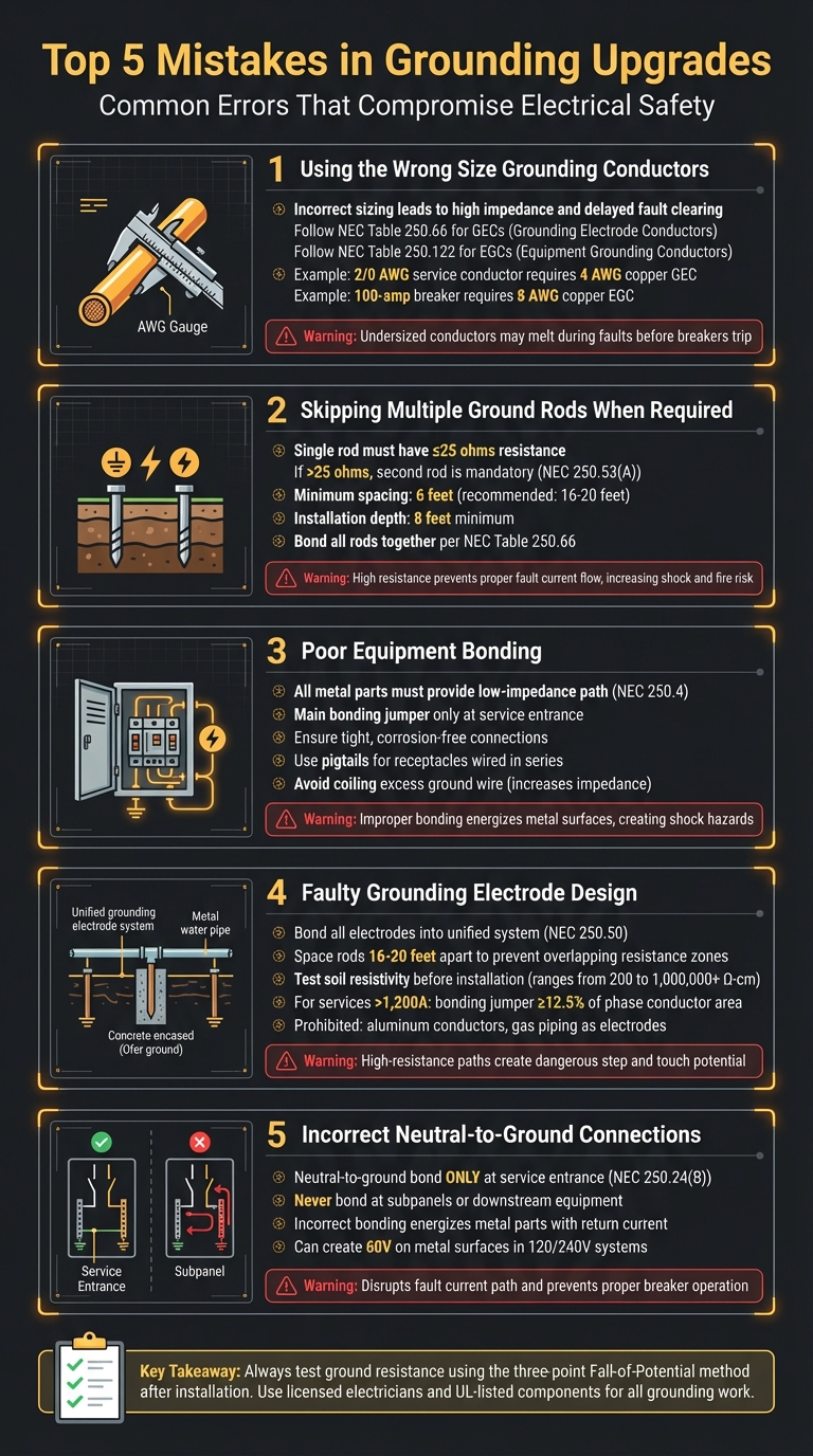
Using the Wrong Size Grounding Conductors
Incorrect sizing of Grounding Electrode Conductors (GECs) or Equipment Grounding Conductors (EGCs) can lead to high impedance and delayed fault clearing. Always follow NEC Tables 250.66 and 250.122 for proper sizing. -
Skipping Multiple Ground Rods When Required
If a single ground rod exceeds 25 ohms resistance, a second rod is mandatory. Proper spacing (16–20 feet apart) and installation depth (8 feet) are crucial for effectiveness. -
Improper Equipment Bonding
Poor bonding of metal parts or raceways can leave them energized, creating shock hazards. Ensure all connections are tight, corrosion-free, and meet NEC Article 250.4 standards. -
Faulty Grounding Electrode Design
Overlapping resistance zones or using prohibited materials like aluminum can weaken the system. Bond all electrodes into a unified system and test soil resistivity before installation. -
Incorrect Neutral-to-Ground Connections
Neutral-to-ground bonds should only occur at the service entrance. Downstream connections can energize metal parts and disrupt fault current paths.
Key Tip: Always test ground resistance using the three-point Fall-of-Potential method after installation. Proper installation, regular testing, and adherence to NEC guidelines ensure safety and reliability.
Top 5 Grounding Upgrade Mistakes and How to Avoid Them
Common Grounding Mistakes
sbb-itb-501186b
1. Using the Wrong Size Grounding Conductors
Choosing the wrong size grounding conductors can lead to serious safety risks and violations of electrical codes. The National Electrical Code (NEC) offers specific guidelines for sizing both Grounding Electrode Conductors (GECs) and Equipment Grounding Conductors (EGCs), and understanding these standards is crucial for proper installation.
Compliance with NEC Standards
The Grounding Electrode Conductor (GEC) connects the electrical system to the earth and must be sized according to the largest service-entrance conductor, as specified in NEC Table 250.66. For example, a 2/0 AWG service conductor requires a 4 AWG copper GEC. However, there are exceptions: if the GEC connects only to ground rods, it doesn’t need to exceed 6 AWG copper, and for concrete-encased electrodes (Ufer grounds), the maximum required size is 4 AWG copper.
"Properly sizing the Grounding Electrode Conductor (GEC) per NEC 250.66 is a fundamental skill for every licensed electrician." – ExpertCE
On the other hand, the Equipment Grounding Conductor (EGC) is sized based on the rating of the circuit breaker or fuse, as outlined in NEC Table 250.122. For instance, a 100-amp breaker requires an 8 AWG copper EGC, while a 200-amp breaker calls for a 6 AWG copper conductor. When phase conductors are upsized to reduce voltage drop, the EGC must also be proportionally upsized to maintain compliance.
Adhering to these tables is not just about meeting code requirements; it ensures effective fault clearing and system reliability.
Safety Implications
Improperly sized grounding conductors can severely compromise safety. Undersized conductors increase impedance, which delays breaker tripping during faults. This delay can lead to dangerous conditions. Tim Janof, Associate and Senior Project Manager at Sparling, highlights this risk:
"Under-sized grounding conductors may melt during a fault before they serve their purpose of providing a continuous low-impedance current path back to the source."
To put it in perspective, an undersized conductor can handle only 1 amp per 42.25 circular mils for 5 seconds. For example, a 3/0 AWG conductor can sustain approximately 3,972 amps for that duration. However, if the available fault current surpasses the conductor’s capacity, the wire may fail before the breaker trips. This failure leaves metal surfaces energized, increasing the risk of shock and fire hazards.
Proper Installation Techniques
Proper installation is just as important as correct sizing. Ground wires should follow straight, gradual paths to minimize impedance - coiling them can increase AC impedance due to mutual inductance, which raises voltages during transients. For large services over 1,200 amps, the main bonding jumper must be at least 12.5% of the phase conductor area. For instance, a 4,000 A service using multiple 500 kcmil conductors requires a 700 kcmil bonding jumper.
When using aluminum conductors, always apply antioxidant compounds and use connectors rated for aluminum to prevent high-resistance connections. Additionally, when running multiple nonmetallic raceways in parallel, ensure each raceway contains a properly sized wire-type EGC, based on the full rating of the overcurrent protection device.
These installation practices are critical to maintaining system safety and avoiding one of the most hazardous mistakes in grounding upgrades.
2. Not Installing Multiple Ground Rods When Required
Compliance with NEC Standards
The National Electrical Code (NEC) states that a single ground rod should have a resistance of 25 ohms or less. If the resistance exceeds this threshold, NEC 250.53(A) requires adding a second ground rod. Since testing ground resistance often demands specialized tools that aren't typically used in residential settings, many contractors skip the testing step and install two ground rods by default. As ExpertCE explains:
"The common and accepted practice is to install a second electrode... to automatically meet the requirement for a complete grounding electrode system."
Once a second rod is installed, the NEC does not require the combined system to meet the 25-ohm standard. However, proper installation is still essential. NEC mandates a minimum spacing of 6 feet between rods, but spacing them 16 to 20 feet apart ensures better performance. Each rod must be embedded at least 8 feet deep in the soil, as outlined in NEC 250.53(G). If rocky conditions prevent vertical installation, rods can be driven at an angle up to 45 degrees or buried in a trench at least 30 inches deep. Additionally, all rods must be bonded together using a conductor sized according to NEC Table 250.66.
These requirements are essential for maintaining a safe and effective grounding system.
Safety Implications
Skipping the installation of a second ground rod when needed can lead to serious safety issues. High resistance in the grounding system can prevent the proper flow of fault current, potentially leaving metal equipment energized during a fault. This increases the risk of electric shock, fire, and hazardous "step and touch potential" around equipment. nVent ERICO highlights this danger:
"Current will always follow the path of least resistance; therefore, if low impedance grounding is not in place, the alternate path to ground may include sensitive equipment or the human body."
If ground resistance is too high, overcurrent devices may not trip quickly enough, leaving dangerous conditions unresolved. A well-designed grounding electrode system also plays a crucial role in dissipating lightning energy, stabilizing voltage, and protecting sensitive electronics from electrical noise.
Proper Installation Techniques
To avoid these risks, it’s essential to use proper installation methods. Tim Janof, P.E., Senior Project Manager at Sparling, explains:
"Ground rods spaced less than two rod-lengths apart will interfere with each other because their effective resistance areas will overlap."
For standard 8-foot rods, spacing them 16 to 20 feet apart prevents overlapping resistance zones and improves performance. Before installation, always call 811 to locate underground utilities like gas or water lines. Use a ground rod driver or a sledgehammer to drive the rod fully into the soil until it is flush with or below ground level. Position rods under the roof’s drip line to take advantage of moist soil, which lowers resistance. Finally, use listed, irreversible, direct-burial connectors to attach the grounding electrode conductor and ensure the wire remains as straight as possible to minimize impedance for lightning and surge protection.
3. Poor Equipment Bonding to the Grounding System
Compliance with NEC Standards
According to NEC Article 250.4, all conductive materials that could become energized must provide a low-impedance path back to the supply source. This ensures overcurrent devices trip properly during a fault situation. The main bonding jumper - linking the grounded neutral conductor to the equipment grounding conductor - should only be installed at the service disconnecting means. Placing it in subpanels violates code and creates safety risks.
When using metal raceways as grounding conductors, it’s crucial to ensure all connectors are tightly secured and free from corrosion. For grounding electrode connections, NEC 250.70 specifies approved methods such as listed pressure connectors or exothermic welding. Additionally, when wiring devices like receptacles in series, the incoming and outgoing ground wires should be joined with a short jumper (pigtail). This prevents the removal of one device from breaking the grounding continuity for the entire circuit. These practices are critical for maintaining system safety and performance.
Safety Implications
Improper bonding can allow voltage to build up on metal surfaces like tool casings, raceways, and enclosures, turning them into shock hazards. High impedance in the grounding path can delay breaker tripping, which is dangerous because fault currents need to be at least five times the overcurrent device rating to trip effectively (e.g., 2,000 amps for a 400-amp breaker). If equipment isn’t properly bonded, anyone touching it may become the unintended path to ground. South Atlantic LLC highlights the risks:
"Improperly grounded appliances and outlets are a major shock hazard and can easily cause an electrical fire in your home."
Additionally, incorrect neutral-to-ground connections downstream can lead to circulating currents and voltage on equipment casings. This not only increases the risk of shock but also creates fire hazards in both residential and commercial environments.
Aside from safety concerns, poor bonding also impacts the performance and reliability of the entire electrical system.
System Performance and Reliability
Coiling extra ground wire inside panels can create high-impedance paths due to mutual inductance. This can result in dangerously high voltages during transient events like lightning strikes. Hua Yan, P.E., LC, RCDD, explains the consequences of ground loops caused by improper bonding:
"can significantly impact system performance and safety. They can introduce common-mode noise in electronic circuits, degrade power quality, hinder ground fault protection, damage equipment, and even pose shock or fire hazards."
Neglecting proper maintenance of metal raceways - such as failing to clean dirt or remove rust - can disrupt the low-impedance path required by NEC 250.4, ultimately compromising the system’s reliability.
Proper Installation Techniques
To address these risks, proper installation methods are non-negotiable. Ground conductors should use short, direct paths with gradual bends to minimize impedance. Avoid coiling excess wire, as this increases inductance and creates hazards during faults.
Inspect all setscrews, locknuts, and threads on metal raceways to confirm they are secure, and clean off any dirt or corrosion to maintain a continuous low-impedance path. When upgrading circuits for appliances like ranges or dryers, always use a 4-wire branch circuit to separate the neutral and equipment ground - a standard since the 1996 NEC. Communication systems (telephone, CATV, satellite) must also be bonded to the main grounding system using an Intersystem Bonding Termination (IBT) to ensure a unified ground reference. Lastly, always perform electrical continuity tests after relocating or repairing equipment to ensure the ground path remains intact.
4. Poor Grounding Electrode System Design
Compliance with NEC Standards
A well-designed grounding electrode system is essential for managing voltages caused by lightning and surges, stabilizing voltage levels during normal operations, and safely dissipating static electricity. According to NEC 250.50, all grounding electrodes - such as metal water pipes, ground rods, and concrete-encased steel - must be bonded together to form a single, unified system. Additionally, the NEC requires a second ground rod if the resistance of the first rod exceeds 25 ohms. To ensure effectiveness, rods should be spaced 16–20 feet apart, as the minimum spacing of 6 feet is insufficient.
Tim Janof, P.E., Associate and Senior Project Manager at Sparling, highlights a common issue:
"Ground rods spaced less than two rod-lengths apart will interfere with each other because their effective resistance areas will overlap."
Another often-overlooked requirement involves the sizing of the main bonding jumper. For larger services, this conductor must be at least 12.5% of the largest phase conductor's area. For instance, in a 4,000-amp service with 11 sets of 500 kcmil conductors, the main bonding jumper must be at least 700 kcmil. This far exceeds the common misconception that 3/0 AWG is the maximum required size. Failing to meet this standard not only violates NEC guidelines but also poses serious safety risks.
Safety Implications
An improperly designed grounding electrode system can lead to high-resistance paths that increase the risk of electrical shock. If the earth resistance is too high, fault currents cannot discharge effectively, creating dangerous step and touch potential hazards. Soil resistivity varies widely, from 200 ohm-cm for seawater to over 1,000,000 ohm-cm in rocky terrain. Using prohibited materials like aluminum conductors or underground gas piping as grounding electrodes can exacerbate risks due to corrosion and code violations. For industrial or high-load systems, resistance values below 1 ohm are often the target, while residential systems typically aim for a resistance of 25 ohms or less.
System Performance and Reliability
To ensure reliability, it's important to distinguish between resistance and impedance in grounding systems. While DC resistance measurements are valuable, the system must also maintain low AC impedance to handle transient events effectively. Coiling excess ground wire, for example, can create mutual inductance, significantly increasing impedance during lightning strikes or other high-frequency events. The TIA/EIA J-STD-607-A standard recommends limiting potential differences between grounding points to 1 volt to reduce ground loops in low-voltage systems.
Soil conditions also heavily influence long-term system reliability. For example, garden soil typically has a resistivity range of 500 to 5,000 ohm-cm, while clay can range from 1,000 to 25,000 ohm-cm. Without proper treatment materials like bentonite or charcoal, electrodes installed in high-resistance soils may degrade over time, leading to equipment failures and erratic system faults.
Proper Installation Techniques
Effective grounding begins with accurate soil resistivity measurements before installation. The three-point method is a reliable way to measure ground resistance and account for variables such as encountering rock that prevents proper rod depth. Grounding electrodes should be installed at a depth of 8 to 10 feet, and metal water pipes should be bonded within the first 5 feet of entering the building.
To minimize impedance, grounding conductors should be as short and straight as possible, with gradual bends instead of sharp angles. For a fault duration of 5 seconds, conductors must have a withstand rating of 1 ampere per 42.25 circular mils. Ensure all connections are tight, free from corrosion, and properly sized according to the manufacturer’s time-current curves for overcurrent protection devices.
5. Incorrect Equipment-Grounding Conductor to Neutral Connections
Compliance with NEC Standards
Connecting the neutral to the equipment-grounding conductor (EGC) on the load side goes against NEC Section 250.24(B). According to this standard, the neutral-to-ground bond should only occur at the service entrance, using a main bonding jumper as outlined in NEC 250.28. Mike Holt, a respected NEC consultant, emphasizes:
"If a neutral-to-case connection is made on the load side of the service disconnect, objectionable neutral current will flow on conductive metal parts of electrical equipment."
For feeders supplying buildings, NEC 250.32(B) explicitly prohibits connecting the supply neutral to the remote disconnect enclosure. Instead, the grounding electrode conductor must terminate at the equipment grounding terminal, not the neutral terminal.
Safety Implications
This type of violation doesn’t just breach NEC standards - it introduces serious safety risks. When the neutral bonds to the EGC on the load side, normal return current can energize non-current-carrying metal parts like raceways, enclosures, or appliance casings. This creates dangerous step and touch potential hazards. For instance, if the neutral opens and the ground resistance measures 25 ohms, metal parts in a 120/240 V system could reach about 60 volts above earth potential.
Additionally, an open neutral in a nearby building could send return current through shared conductive paths, such as metal water pipes or coaxial cables, energizing your grounding system - even if your installation is correctly wired. To avoid such risks, always test grounding electrode conductors with an ammeter before disconnecting any connections.
System Performance and Reliability
Incorrect neutral-to-ground connections can also disrupt system performance. They interfere with the proper fault current path, which is crucial for safety. If the grounding system is compromised, fault current may rely on the earth’s high resistance, which NEC 250.4(A) clearly states "shall not be considered an effective ground-fault current path". This can prevent overcurrent devices from tripping during a fault, leaving circuits energized and increasing the risk of damage or injury.
Fault current will always flow through all available paths back to the source, with more current traveling through lower-impedance paths. As ERICO highlights:
"Current will always follow the path of least resistance; therefore, if low impedance grounding is not in place, the alternate path to ground may include sensitive equipment or the human body".
Proper Installation Techniques
To ensure safety and system reliability, follow these installation practices:
- Confirm that the main bonding jumper is located only at the service entrance. Avoid bonding the neutral and EGC at downstream subpanels or equipment.
- After moving or repairing equipment, test all ground path connections - like setscrews, locknuts, and threads - for continuity before restoring power.
- Inspect metal raceways for dirt, rust, or corrosion, as these can compromise a low-impedance circuit.
- When troubleshooting neutral issues, use an ammeter to compare phase and neutral currents to detect if a grounding conductor is unintentionally carrying current from an external source.
- Keep grounding conductors as short and straight as possible, using gradual bends to reduce impedance. Avoid leaving excess wire coiled in panels, as coils can increase AC impedance through mutual inductance, leading to elevated voltages on equipment during transients.
Tips for Successful Grounding Upgrades
Start by testing ground resistance using the Fall-of-Potential method – the industry standard. This three-point testing approach involves driving two temporary test probes into the ground in a straight line from your electrode. According to nVent ERICO:
"The best way to guarantee that the grounding system has a sufficient resistance is to measure that resistance using the three‐point method".
Perform this test immediately after installation to ensure the system complies with NEC requirements.
Keep detailed records of resistance values, weather, and soil moisture conditions during testing. Ground resistance can vary significantly due to changes in soil resistivity, moisture levels, and temperature. Retesting periodically - especially when seasons change - is a good practice. For example, moist mixed soil might show a resistivity of about 1,500 Ω-cm, while dry gravel could exceed 1,000,000 Ω-cm. Maintaining thorough records helps with ongoing system verification and simplifies future maintenance.
Always rely on licensed electricians for grounding upgrades and testing. NEC Article 250 covers complex topics like conductor sizing, bonding jumper specifications, and proper neutral-to-ground separation. These tasks require professional expertise to ensure safety. Licensed electricians understand that electricity flows through all available paths in inverse proportion to their impedances, not just the "path of least resistance". Their knowledge ensures every connection meets UL standards and provides long-term safety.
Use only high-quality, UL-listed components for grounding connections. Cutting corners with subpar materials - like wrapping wire around a pipe instead of using a proper UL-listed clamp - can lead to unreliable bonding. This compromises the low-impedance path required by NEC 250.4. To avoid these risks, platforms like Electrical Trader offer dependable grounding equipment, helping contractors stay compliant and avoid costly mistakes.
Streamline your installation practices to ensure a reliable grounding system. Before energizing, verify raceway continuity by testing setscrews, locknuts, and threads. Also, inspect metal surfaces for dirt, rust, or corrosion, as these can disrupt your low-impedance circuit.
Conclusion
Getting grounding upgrades right demands precision and a deep understanding of best practices. Skipping steps or making errors can jeopardize safety, spark electrical fires, and damage equipment. As nVent ERICO emphasizes:
"Preventable mistakes in the electrical grounding system can leave it vulnerable to ground faults, side flashes and electronic noise, any of which could result in fire, damage to structures and personal injury".
Adhering to NEC standards isn’t optional - it’s the foundation for safeguarding both people and property. A well-grounded system eliminates stray voltage on metal surfaces, ensures overcurrent devices operate correctly during faults, and shields sensitive electronics from transient over-voltages.
To avoid costly fixes later, prioritize grounding during the design phase. Work with licensed professionals who understand that proper grounding - meeting UL standards and maintaining a low-impedance path - is critical for safety.
Use the three-point method to test ground resistance, document your results meticulously, and choose only UL-listed, high-quality components. Regular testing and inspections will keep your grounding system dependable and safe over time.
FAQs
When do I need to upsize the equipment grounding conductor (EGC)?
When you increase the size of the ungrounded circuit conductor, you also need to upsize the equipment grounding conductor (EGC). This adjustment is critical to staying compliant with NEC 250.122(B), which ensures the grounding conductor remains proportional to the circuit conductor. This proportionality is essential for maintaining a safe and effective grounding system.
How can I tell if my grounding system has a dangerous neutral-to-ground bond?
Improper bonding in a subpanel, rather than the main panel, can create a hazardous neutral-to-ground connection. This mistake can lead to safety risks and cause electrical currents to follow incorrect paths. Warning signs include measuring zero volts between neutral and ground under load or detecting unintended current on grounding conductors. To ensure safety and proper system functionality, make sure all bonds are located exclusively at the main panel.
What ground resistance should I aim for in a typical U.S. home?
For a standard U.S. home, the ground resistance should ideally be 25 ohms or lower. This level helps maintain effective electrical grounding, ensuring safety during use.


