Transformer Grounding: Step-by-Step Guide
Proper transformer grounding is essential for safety, equipment protection, and system stability. It prevents electric shocks, stabilizes voltage, and ensures compliance with the National Electrical Code (NEC). This guide covers the essentials, including electrode selection, conductor sizing, and installation practices.
Key Takeaways:
- Purpose of Grounding: Protects people, prevents voltage surges, and stabilizes system voltage.
- NEC Compliance: Follow Article 250 for proper grounding of separately derived systems.
- Tools & Materials: Copper wires, grounding rods, torque wrenches, and resistance testers are crucial.
- Installation Tips: Use short conductor runs, avoid sharp bends, and ensure tight connections.
- Testing: Verify resistance is ≤5 ohms and document all results for compliance.
Grounding done right ensures safety and system reliability while meeting regulatory standards.
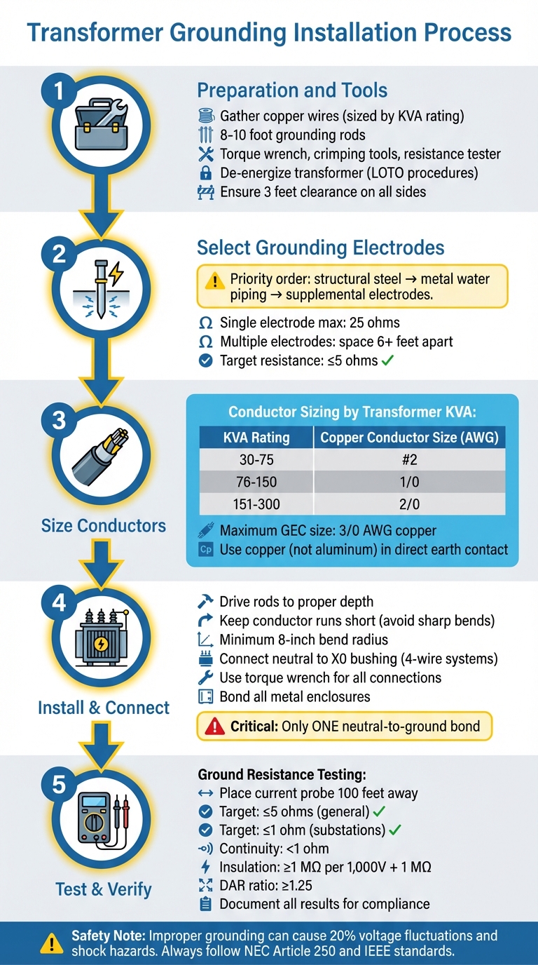
Transformer Grounding Installation Process: 5 Essential Steps
Grounding, Transformers [250.30, 2020 NEC]

sbb-itb-501186b
Preparation and Tools
Before starting, gather all necessary tools and materials to ensure the installation meets code requirements and minimizes safety risks. The specific items you'll need depend on the transformer's KVA rating, the site conditions, and whether the setup is indoors or outdoors.
Required Tools and Materials
For conductors, use copper wires sized according to the transformer's KVA rating. Here's a quick guide:
- 30–75 KVA: #2 AWG copper wire
- 76–150 KVA: 1/0 AWG copper wire
- 151–300 KVA: 2/0 AWG copper wire
The NEC limits the Grounding Electrode Conductor (GEC) size to a maximum of 3/0 AWG copper, regardless of the service size.
For grounding electrodes, use 8- to 10-foot copper or galvanized steel rods. You'll also need reliable components like listed clamps, properly sized lugs, and bonding jumpers for secure connections. If you're working with aluminum conductors, apply anti-oxidation compounds to prevent high-resistance joints that could compromise the grounding system.
Essential tools include:
- Torque wrench: For tightening bolts to manufacturer specifications
- Crimping tools: To secure lugs
- Cable stripping tools: For preparing wires
- Earth resistance tester: To confirm the system achieves a resistance of less than 5 ohms
For outdoor setups, use rigid conduit for neutral connections, cable glands, and heat-shrink tubing to protect against moisture.
The transformer should sit on a reinforced concrete pad at least 4–6 inches thick, extending 6 inches beyond the transformer base. In earthquake-prone areas, include seismic anchors and vibration isolation pads under the mounting points.
Once you've gathered your materials, evaluate the site for safety and readiness.
Safety Measures and Site Assessment
Before starting any work, de-energize the transformer and implement Lockout/Tagout (LOTO) procedures. Electrical hazards lead to approximately 76,000 worker injuries annually, with over 20% of workplace fatalities in construction and power industries caused by electric shock. Full PPE is mandatory - this includes insulated gloves, arc-flash suits, safety goggles, hard hats, and electrical gumboots.
Conduct a thorough site inspection. Ensure the transformer has at least 3 feet of clearance on all sides for proper maintenance access and cooling airflow. Confirm the concrete pad is level and capable of supporting the transformer's full weight, including oil. For outdoor installations, check that the enclosure is weather-resistant (Type 3R) and that the site has adequate drainage to prevent flooding.
If the soil has high resistivity, you may need chemical grounding electrodes or grounding plates to meet resistance requirements. For installations at higher altitudes (above 3,280 feet or 1,000 meters), adjust the ratings accordingly. Finally, verify that your plan complies with NEC Article 250, IEEE standards, and any local codes before beginning work.
Choosing Grounding Electrodes and Conductors
Once you've completed site preparation and safety checks, the next step is selecting the right grounding electrodes and conductors. Your choices should align with transformer specifications, on-site conditions, and code requirements. These decisions play a key role in how effectively your system manages voltage surges and maintains steady operation.
Grounding Electrode Options
Start by identifying the closest grounding electrode to your transformer. For separately derived systems, the NEC recommends prioritizing certain electrode types in this order: building structural steel, metal water piping within 5 feet of entry, and then supplemental electrodes like ground rods or plates. These components connect the system to the earth, helping to limit voltage surges and stabilize secondary voltage during normal operation.
If soil conditions are challenging, choose an electrode type suited to the environment. For example, in desert areas with little rainfall and no underground water table, concrete-encased electrodes (Ufer grounds) often provide the best ground resistance for the cost. In rocky terrains where driving rods vertically to a depth of 8 feet isn't feasible, you can install them at an angle of up to 45 degrees or bury them horizontally in a trench at least 30 inches deep.
When a single rod, pipe, or plate electrode has a resistance higher than 25 ohms, you must add another electrode at least 6 feet away. For locations with deep water tables - around 30 feet below the surface - 2 ft × 2 ft × 1/8 inch copper plates are a good option for achieving the necessary resistance.
Conductor Sizing and Materials
To size the Grounding Electrode Conductor (GEC), consult NEC Table 250.66, which bases sizing on the largest ungrounded phase conductor. Keep in mind that the 12.5% rule applies to system bonding jumpers but not to the GEC. For Equipment Grounding Conductors (EGC), refer to NEC Table 250.122, which sizes conductors based on the overcurrent protective device's rating.
Copper is the standard material for most installations because it works well in direct contact with earth, concrete, and masonry. However, aluminum and copper-clad aluminum (CCA) conductors should not be used in direct contact with earth, masonry, or corrosive environments, such as those near salt water, pools, or fountains. If your GEC is smaller than 6 AWG, use a raceway or cable armor to protect it from physical damage.
In environments prone to high-frequency noise, opt for wide, flat conductors instead of round ones, as they reduce inductive reactance at higher frequencies. When using a metal water pipe system as the electrode, install a bonding jumper around any water meters or filtering devices to ensure electrical continuity.
With the electrodes and conductors selected and sized correctly, you’re ready to move on to the installation phase to ensure secure grounding for your transformer.
Installation Steps
With your electrodes and conductors chosen, it’s time to install them and make the necessary connections. Each step requires precision to ensure a low-resistance path and adherence to NEC standards.
Installing the Grounding Electrodes
Begin by driving copper or galvanized steel grounding rods into the soil to create a solid connection to the earth. For larger industrial setups, grounding grids or plates can provide better conductivity.
When routing the grounding electrode conductor, keep runs as short as possible and avoid sharp bends. Maintain a minimum 8-inch radius to reduce mechanical stress. Use rigid conduit to protect the conductor from physical damage, especially in areas with high foot or vehicle traffic. Secure the grounding electrode conductor to the electrode using listed clamps, and install bonding jumpers between equipment frames to ensure a continuous metallic path. The system's grounding resistance should not exceed 5 ohms.
Connecting Grounding Conductors to the Transformer
The system bonding jumper plays a critical role in this process. Duke W. Schamel, P.E., President of Electrical Service Solutions, Inc., explains:
"The objective of the system bonding jumper is to connect the grounded conductor (neutral), supply-side bonding jumper, and the equipment grounding conductors... required to create an effective ground-fault current path".
This jumper must be installed at the connection point where the grounding electrode conductor links to the separately derived system.
In 4-wire systems, connect the neutral conductors to the X0 bushing - never leave them taped off inside the enclosure. Howard Eaton, VP & GM at Southwest Electric Co., emphasizes:
"Failing to properly connect and ground the system neutral in 4-wire systems establishes what is often called a 'floating neutral'... this condition creates an extremely dangerous touch potential hazard".
Improper connections can cause phase voltages to fluctuate by as much as 20%.
Before making connections, strip the insulation according to the manufacturer’s specifications and apply anti-oxidation compound to aluminum conductors. Use a torque wrench to tighten all connections to the recommended values - this ensures reliable, long-term electrical contact.
Bonding Equipment and Enclosures
Once the conductor connections are secure, all metal enclosures and structural components need to be bonded to complete the grounding system.
Bond the transformer's metallic enclosure to the grounding system to prevent it from becoming energized during a fault. This can be done through metal-to-metal contact at the base or by using a dedicated bonding jumper. The NEC also requires bonding the grounded conductor to the nearest available metal water piping system and exposed structural building steel in the area served by the transformer.
Ensure there is only one neutral-to-ground bond at the transformer or the first disconnecting means. Avoid creating neutral-to-ground bonds at subpanels supplied by the transformer, as this can lead to ground loops and cause neutral current to flow through the equipment grounding system. For large services using parallel raceways, install an equipment grounding conductor in each raceway, sized according to NEC Table 250.122 based on the overcurrent device rating.
Grounding conductors should be identified with continuous green insulation, green with yellow stripes, or left bare as specified by NEC 250.119. Finally, maintain at least 3 feet of clearance around the transformer to allow for maintenance access and proper cooling airflow.
Testing and Verification
Once all grounding components are in place, testing ensures the system's reliability and compliance with safety standards. Before starting any test, de-energize the transformer, isolate it from power sources, and disconnect all ground connections. These tests confirm that each grounding connection meets the required safety benchmarks.
Ground Resistance Testing
To perform this test, place the current probe (C) at least 100 feet away from the transformer to avoid interference. Position the potential probe (P) in a straight line between the transformer and the current probe. Set the tester to 128 Hz and take 5–6 readings, moving the potential probe in 10% increments toward the current probe. As noted by the ROOQ Group:
"The peak value where the curve flattens is the true resistance of the earth electrode".
The results should meet the specified resistance values: generally, 5 ohms or lower for most installations. The NEC sets a maximum of 25 ohms for a single electrode and 10 ohms for multiple electrodes. For larger substations, IEEE 142 recommends aiming for 1 ohm or less.
Continuity and Insulation Testing
After verifying the earth resistance, check the continuity and insulation of all connections. Continuity testing ensures that each grounding connection provides a low-resistance path, typically under 1 ohm. Use a precision ohmmeter to measure winding resistance and detect any increases that might lead to overheating or coil damage. Inspect for signs of corrosion, loose hardware, or improper bonding.
For insulation resistance (IR) testing, use a megohmmeter with a scale of at least 20,000 MΩ. Disconnect all high-voltage (HV), low-voltage (LV), and neutral connections before testing. Take 1-minute resistance readings between each set of windings and ground. Calculate the Dielectric Absorption Ratio (DAR) by dividing the 60-second reading by the 30-second reading. A DAR below 1.25 signals the need for further investigation. As a general guideline, insulation resistance should be at least 1 MΩ per 1,000 V of applied test voltage, plus 1 MΩ. Normalize all test values to 68°F (20°C) for consistency.
Compliance Documentation
Keeping thorough records during testing is essential for audits and future maintenance. Document the test date, equipment used (e.g., a Fluke 1625-2), probe distances, resistance readings, soil conditions, and temperature. Including photos of grounding connections and GPS coordinates for buried electrodes helps streamline future inspections. Compare your findings against standards like NFPA 70 (NEC), IEEE 142, or NESC (ANSI C2) to confirm compliance with safety requirements.
Detailed documentation is critical because high-impedance ground-fault paths are hard to detect and are only used during ground faults. Accurate records not only confirm that the system meets code requirements but also ensure a reliable and safe ground-fault current path.
Conclusion
Summary of Key Points
Transformer grounding is essential for protecting personnel, preserving equipment, and ensuring system stability. The process involves careful preparation - like gathering the right tools, evaluating site conditions, and adhering to NEC standards. Key steps include choosing suitable grounding electrodes, correctly sizing conductors, and ensuring system resistance stays at or below 5 ohms.
Proper installation matters. Electrodes must be installed at the right depth, connections should be tight and resistant to corrosion, and all metallic enclosures need to be bonded. Failing to do so can result in phase voltage variations of up to 20%, leading to potential equipment failure and shock hazards. As Howard Eaton, VP & GM at Southwest Electric Co., aptly puts it:
"The life and safety of your electrical distribution system begins at installation".
Testing is a critical step to confirm compliance with safety standards. Ground resistance testing, continuity checks, and insulation resistance measurements ensure fault currents can safely dissipate into the earth. Ongoing maintenance is equally important - monthly visual inspections and quarterly insulation tests help maintain system reliability over its 30+ year lifespan. Keeping detailed records of these tests supports compliance with NFPA 70, IEEE 142, and local utility regulations.
Where to Find Electrical Equipment
Once your grounding system has passed all safety checks, sourcing materials from reliable suppliers is key to long-term performance. High-quality components are the backbone of a safe and durable grounding system. Electrical Trader is an excellent resource, offering a wide range of products, including transformers, grounding conductors, copper-bonded ground rods, and testing tools. Their platform connects buyers with both new and used electrical equipment, making it a convenient solution whether you're installing a small transformer or upgrading a substation. Access to properly rated materials ensures your system will handle fault conditions safely and effectively.
FAQs
Where should the neutral-to-ground bond be made?
The neutral-to-ground bond should be established at the transformer's neutral terminal, usually at the main or primary connection point. Grounding the transformer correctly connects its neutral to a low-resistance ground system, which is crucial for safety and protecting the system. This bond also creates a reliable path for ground-fault currents, which can be located either at the transformer or the main panel, depending on the specific system design.
What if my ground resistance test is too high?
If your ground resistance test shows a high reading, it means the grounding system isn’t effectively providing a low-impedance path to the earth. This can put both safety and equipment at risk. Common culprits include corrosion, loose connections, or undersized grounding conductors. To address the issue, consider adding more grounding electrodes or increasing the size of the conductors. Regular testing and upkeep are essential to catch and fix these problems before they escalate.
Do I need different grounding for indoor vs. outdoor transformers?
Yes, grounding requirements for transformers vary depending on whether they are installed indoors or outdoors, primarily due to differences in application and safety considerations. Outdoor transformers often require extra grounding measures, such as dedicated ground rods, to comply with NEC standards and to account for exposure to environmental factors like moisture and lightning. On the other hand, indoor transformers adhere to standard grounding practices, emphasizing proper bonding and maintaining system safety within a controlled environment. In both cases, compliance with electrical codes is essential to ensure reliable operation and adequate protection.