How to Prepare Transformer Foundations
A well-prepared transformer foundation ensures stability, safety, and long-term performance. Here's what you need to know:
- Key Steps: Site assessment, load calculations, material selection, and construction.
- Site Prep: Clear and level the area, install drainage, and ensure access for maintenance.
- Materials: Use concrete with at least 3,000 psi strength, reinforced with rebar or wire mesh, and a gravel sub-base for stability.
- Safety: Grounding systems must comply with NEC standards (≤1 ohm for substations). Include oil containment systems for transformers with insulating oil.
- Construction: Pour concrete with proper curing (7 days minimum) and embed anchoring rails for transformer stability.
Why it matters: A strong, level foundation prevents structural issues, ensures safety, and supports reliable transformer operation for years. Keep reading for detailed steps on site preparation, material selection, and compliance standards.
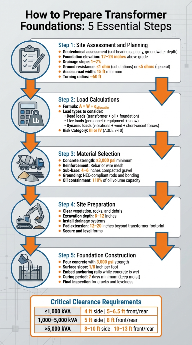
5-Step Transformer Foundation Preparation Process with Key Specifications
Installing transformer pad foundation | DIY House Build
sbb-itb-501186b
Site Assessment and Planning
Before starting any work, it's crucial to assess the site thoroughly. This step ensures the chosen location can safely support the transformer while identifying potential issues that could lead to expensive errors down the line.
Evaluating Site Conditions
Start with a geotechnical assessment to understand the soil's bearing capacity, groundwater depth, and compressibility. These factors determine whether the foundation will require a simple slab-on-grade, isolated footings, or deeper pile foundations. The soil must handle both the transformer's static weight and dynamic forces like vibrations, wind loads, and seismic activity.
Environmental factors also influence foundation design. For instance, sites near water bodies may need enhanced oil containment systems capable of holding 110% of the transformer's oil volume. In seismic zones, deeper reinforced footings are necessary, while frost protection may be required in colder climates and insulation in hotter areas.
The foundation plinth should be elevated about 12–24 inches above grade to prevent water pooling and ensure proper drainage. A drainage slope of 1–2% is recommended to guide water away from the equipment. Additionally, grounding systems should achieve a ground resistance of ≤1 ohm for substations or ≤5 ohms for general installations.
"A transformer's foundation is not merely a concrete slab - it is a precision-engineered support structure that must withstand static and dynamic loads, resist seismic and thermal stresses, contain oil in case of leaks, and accommodate proper grounding and access." – Taishan Transformer
Transport routes should also be verified before finalizing the site. Heavy transformers require access roads at least 15 ft wide with a turning radius of about 60 ft. Check for bridge load ratings, overhead clearances, and obstacles that could interfere with delivery. This comprehensive evaluation lays the groundwork for accurate load calculations.
Calculating Load Requirements
Precise load calculations are essential for designing a foundation that can handle the transformer's weight and operational demands. Use the formula A = W ÷ q_allowable, where W is the total load (transformer, oil, and ancillary equipment) and q_allowable is the soil's bearing capacity. Always confirm transformer specifications using the manufacturer's final cut sheet before proceeding.
The foundation must support various load types:
- Dead loads: The transformer's weight, oil, and the foundation itself.
- Live loads: Maintenance personnel, temporary equipment, and snow or ice buildup.
- Dynamic loads: Vibrations, short-circuit forces, and wind loads that apply lateral pressure.
For substation transformers, ASCE 7-10 typically classifies them as Risk Category III or IV, reflecting their critical role and economic impact. Apply safety factors according to local codes and ensure the foundation's natural frequency avoids resonance with operational loads.
Planning for Maintenance Access
Proper maintenance access is a must. Clearances should follow the guidelines outlined below:
| Transformer Rating | Min. Side Clearance | Front/Rear Clearance | Between Units |
|---|---|---|---|
| ≤1,000 kVA | ~4 ft | 5–6.5 ft | ~6.5 ft |
| 1,000–5,000 kVA | ~5 ft | ~8 ft | 8–10 ft |
| >5,000 kVA / 132 kV+ | 8–10 ft | 10–13 ft | 11.5–16.5 ft |
Rear clearances of 5–6.5 ft allow for radiator maintenance, fan access, and cleaning. Side clearances of 3–5 ft are helpful for accessing nameplates, tap changers, and pressure relief devices. For crane operations during installation, plan for a radius of about 16–23 ft to accommodate boom swing and outrigger placement.
The concrete pad should extend 12–20 inches beyond the transformer's footprint on all sides. This extra space improves air circulation and makes it easier for technicians to perform their work. Include provisions like 20% spare ducts in cable trenches to accommodate future upgrades or cable replacements. Emergency fire access lanes should be about 13 ft wide with a sufficient turning radius. Once these parameters are set, you're ready to move forward with material selection and procurement.
Material Selection and Procurement
Choosing the right materials is crucial for building a transformer foundation that lasts and avoids expensive repairs. For starters, the concrete mix should have a compressive strength of at least 3,000 psi. This ensures the pad can handle heavy loads, resist moisture, and endure freeze-thaw cycles common across many U.S. regions. Essentially, this strength level helps the foundation stand up to both the weight of the transformer and the challenges of outdoor exposure.
Reinforcement plays a big role too. Using rebar or wire mesh helps distribute the weight evenly and reduces the risk of cracking under stress. Beneath the concrete, a 4 to 6-inch layer of compacted gravel or crushed stone is essential. This sub-base layer provides stability and ensures proper drainage, which is critical for long-term durability. Don’t forget to include grounding components, like grounding rods and bonding materials, that comply with National Electrical Code (NEC) standards. These are vital for preventing electrical faults.
Selecting Foundation Materials
Before choosing materials, start by reviewing the transformer's specifications. Details like its weight (both during installation and operation), base dimensions, height, and center of gravity (COG) are key for seismic calculations and overall design. It’s a good idea to document any assumptions you make for clarity later. As DETstru, Structural Engineer, points out:
"If you don't have a final cut sheet on the transformer I would put the max load and transformer size you assumed directly on the drawings... That way if they come back with a transformer that weighs 20% more you can show them exactly what was designed for".
Geotechnical data also plays a role. Information like soil bearing pressure, soil density, and the groundwater table location shapes the foundation’s requirements. For transformers in ASCE 7-10 Risk Category III or IV - those deemed critical for economic or functional reasons - opt for higher safety factors and stronger materials. Depending on local regulations, you might also need fire separation walls or gravel-filled oil retention pits. Being precise with material selection at this stage ensures a solid foundation for the project.
Sourcing Transformers and Components
Reliable suppliers can make a big difference in saving time and reducing potential risks. Electrical Trader (https://electricaltrader.com) is a good resource, offering a variety of new and used transformers, breakers, and power distribution equipment in one convenient marketplace tailored for contractors, electricians, and other end-users.
When sourcing, confirm anchor bolt requirements with your utility provider. Some standards mandate their use for stability, and certain utilities may have specific preferences for their application. Additionally, for padmount transformers, check whether a "Flat Pad" or "Pit Pad" design is needed, as this will influence conduit placement and secondary conductor routing. Once you’ve identified the necessary materials and components, the next step is aligning these choices with your budget.
Budgeting for Materials and Equipment
Costs can vary depending on the project’s size and location, but certain expenses are consistent. Concrete, rebar, gravel, and grounding components make up the bulk of foundation costs, while the transformer itself is usually the most expensive single item. Excavation depths typically range between 8 to 12 inches, depending on soil conditions, so plan for adequate gravel for the sub-base. Also, budget for curing materials - like wet burlap, plastic sheeting, or specialized curing compounds - since keeping the concrete moist for at least 7 days is essential for achieving full strength. Finally, don’t overlook the need for properly secured and leveled forms, whether wooden or metal, before pouring the concrete. With careful planning, you can meet code requirements while staying within budget, avoiding unnecessary over-engineering for conditions that may not apply to your site.
Site Preparation Steps
After selecting your materials and finalizing the budget, the next step is preparing the site for construction. This stage involves removing obstacles, ensuring proper drainage, and constructing support structures. Each part of this process is critical, as it directly impacts the foundation's durability and the transformer's overall performance.
Clearing and Leveling the Site
Start by clearing the site of vegetation, rocks, debris, and any other obstructions. A clean site is essential to prevent organic material from breaking down beneath the foundation, which could cause voids and settling over time. Before clearing, verify local zoning regulations and utility easements to avoid complications.
Once cleared, level the ground to create a stable, uniform base. As Vietnam Transformer highlights, "The site should have a strong and level foundation". Excavation may be required depending on soil conditions, and it's important to establish a compacted sub-base. This will provide a solid, well-drained platform for the transformer foundation. Additionally, ensure the site remains accessible by road or rail to accommodate the delivery of the transformer and any heavy equipment needed for construction. With the ground ready, the next focus is managing water effectively.
Installing Proper Drainage
Water management is a top priority after clearing and leveling the site. Water pooling is a significant threat to transformer foundations, so raising the concrete plinth 12 to 24 inches (300 to 600 mm) above the surrounding grade is essential. This elevation helps keep water away from the foundation during heavy rainfall or flooding. To further direct water away, finish the pad with a 1/8-inch per foot slope.
For oil-filled transformers, drainage becomes even more critical. The floor of any oil containment bund should have a 1 to 2% gradient sloping toward a collection sump. This ensures that any leaked oil flows to a designated area rather than spreading across the site. For example, in June 2025, a 33/11 kV 16 MVA transformer installation near a freshwater lake featured a double-bunded foundation. This included an impermeable liner, a dedicated oil sump, and a drainage system equipped with an oil-water separator and SCADA-integrated sensors. These measures successfully prevented oil discharge while separating stormwater from potential leaks, meeting stringent environmental protection standards.
Additionally, cable trenches should be reinforced, waterproofed, and fitted with sealed covers to prevent flooding. Regular inspections - at least quarterly - are essential to clear debris and maintain proper flow in drainage paths, sumps, and trenches.
Building Support Structures
With the site cleared and drainage addressed, the next step is constructing the support structures for the foundation. Begin by securing forms around the excavation to shape the concrete pad. These forms must be perfectly level before pouring the concrete. Reinforce the foundation with rebar or wire mesh to withstand environmental stresses, freeze-thaw cycles, and the weight of the transformer.
During this phase, grounding components should be integrated into the support structure. Install grounding rods and ensure proper bonding to prevent electrical faults when the transformer is operational. Maintain adequate clearance between the foundation and live components, such as bushings and terminals, to adhere to safety standards. Additionally, ensure sufficient airflow around the transformer for natural or forced cooling. Avoid placing the foundation in flood-prone or high-traffic areas to minimize risks. With the support structures in place, the site is ready for the next step: pouring the concrete foundation.
Foundation Construction Process
After preparing the site and setting up the support structure, the next step is constructing the foundation with precise concrete work. This involves pouring the concrete pad, embedding anchoring rails, and ensuring proper curing to provide long-term, stable support for the transformer.
Pouring the Concrete Pad
Start by excavating the area to a depth of 8 to 12 inches, depending on the soil type and the transformer's weight. Lay down a 4 to 6-inch layer of compacted gravel or crushed stone to create a stable, well-drained sub-base. Surround the area with level and secure forms, and incorporate reinforcement like rebar or wire mesh during the pour to help the pad endure heavy loads and environmental stresses.
Use a concrete mix with a minimum compressive strength of 3,000 psi. Vibrate the concrete during pouring to eliminate air pockets and smooth the surface with a trowel. To ensure proper drainage, maintain a slight slope of about 1/8 inch per foot. Additionally, grounding rods must be installed and bonded in compliance with local electrical codes. As Bin Dong, General Manager at Daelim, emphasizes:
"Allow the concrete to cure properly by keeping it moist for at least 7 days. Use wet burlap, plastic sheeting, or a curing compound to retain moisture. Proper curing enhances the strength and durability of the pad."
Once the pad is poured, embed anchoring elements immediately to secure the transformer.
Installing Anchoring Rails
While the concrete is still wet, embed the anchor rails or points to hold the transformer securely in place. These anchors help minimize movement caused by vibration or thermal expansion. According to utility specifications from Duke Energy, there are two common pad designs: "Flat Pad" designs, which sit level with the ground, and "Pit Pad" designs, which include openings for underground cable management. Always follow the manufacturer's guidelines for anchor placement and spacing to ensure long-term stability.
Curing and Inspecting the Foundation
Allow the concrete to cure for at least 7 days, using wet burlap, plastic sheeting, or a curing compound to maintain moisture. After curing, thoroughly inspect the pad for cracks, defects, or uneven areas. Confirm that the foundation is level and meets both the manufacturer's specifications and local regulations. An uneven pad can cause internal stress within the transformer or lead to issues with the oil level, so this step is critical before proceeding with the installation.
Compliance and Safety Standards
Once the foundation is in place, the next step is ensuring it meets all regulatory standards. In the United States, NEC Article 450 serves as the primary guideline for transformer installations, addressing everything from grounding to ventilation. These checks are critical for merging construction with operational safety, ultimately supporting a reliable installation.
Mike Holt, Owner of Mike Holt Enterprises, underscores the importance of these standards:
"Safe and reliable operation of transformers is crucial - that's where Art. 450 comes in. Part I of Art. 450 contains general requirements such as guarding, marking, accessibility, and ventilation."
Meeting NEC and Local Code Requirements
To comply with NEC guidelines, your foundation must support proper grounding and bonding. This means including a terminal bar for grounding conductors and bonding jumpers [450.10(A)]. Additionally, nonconductive coatings at grounding points should be removed to ensure electrical continuity, or you can use fittings designed to bypass these coatings. The foundation must also allow for a disconnect switch within sight of the transformer - visible and no more than 50 feet away [450.14].
Proper ventilation is another critical factor. Ensure that ventilating openings are not blocked by walls or other obstructions and review the transformer's nameplate for specific clearance requirements before finalizing the pad's location [450.9]. For dry-type transformers rated over 112.5 kVA installed indoors, the room must have a minimum fire rating of 1 hour [450.21(B)]. If you're working with oil-insulated or high-voltage transformers in a vault, the walls, floors, and roof must have at least a 3-hour fire resistance rating, typically achieved with 6-inch-thick reinforced concrete [450.42].
Adding Safety Features
Beyond meeting code requirements, incorporating additional safety measures is essential to minimize electrical hazards and environmental risks. For pad-mounted transformers, maintain at least 10 feet of clearance from buildings and vegetation, and ensure an 8-foot clear path in front of transformer doors to allow for maintenance. If the site has forklift traffic or other vehicle movement, install bollards that provide protection while still allowing maintenance access.
For oil-filled transformers, include containment pits or barriers to prevent flammable insulating oil from spreading in case of a leak or tank rupture. In areas near waterways, passive fire barriers - such as galvanized steel or fire-rated panels - are a safer alternative to sprinkler systems, as they avoid introducing fire suppressant chemicals into the environment. John Sinisi, a Subject Matter Expert at Sinisi Solutions LLC, explains:
"The primary function of passive fire barriers is to contain the spread of fire, explosion, heat, and smoke to a localized area."
Once these safety features are in place, verify their effectiveness using a detailed checklist.
Creating a Safety Checklist
A well-prepared checklist ensures all safety and design standards are met. Key items to include are:
- Securing grounding connections and confirming they are corrosion-free
- Confirming the foundation is level and adheres to manufacturer specifications
- Verifying that all required clearances are maintained
- Checking that drainage systems are functioning properly
- Installing appropriate safety signage
- Marking the horizontal top surfaces of transformers to prevent storage - this space is critical for cooling and safety
- Ensuring fire extinguishers are accessible but not placed in the path of transformer vent exhaust
Conclusion
Summary of Main Steps
Creating a reliable transformer foundation requires careful planning and adherence to specific guidelines. Start by selecting a location free from flooding risks and with sufficient space for maintenance access. Excavate the site to a depth of 8–12 inches and lay down a 4–6 inch compacted gravel sub-base to provide stability and proper drainage. The concrete pad itself must have a compressive strength of at least 3,000 psi and include rebar or wire mesh reinforcement to support the transformer's weight and withstand external stresses. To aid water runoff, finish the surface with a slope of 1/8 inch per foot.
Grounding rods should comply with local codes, typically requiring resistance of ≤5 ohms, and proper bonding must be established before installing the transformer. For oil-filled transformers, containment systems should be designed to hold at least 110% of the oil volume to prevent any potential environmental hazards. Once these steps are completed, your foundation will be ready to support the transformer effectively.
Tips for Success
To ensure the foundation performs well over time, a few extra measures can make a big difference. Proper curing is essential for the concrete's strength and durability. Keep the concrete moist for at least 7 days using wet burlap or plastic sheeting to avoid cracks and structural weaknesses. As Daelim Electric emphasizes:
"Proper curing enhances the strength and durability of the pad".
Before mounting the transformer, thoroughly inspect the foundation for cracks, uneven surfaces, or other defects. Additionally, double-check that all grounding connections are secure and drainage systems are functioning as intended. These final checks ensure compliance with all specifications and codes, laying the groundwork for dependable transformer operation for years to come.
FAQs
Do I need a slab, footings, or piles?
A reinforced concrete pad, usually about 8 inches thick, serves as the main foundation for transformers. While the article doesn't mention the necessity of footings or piles, these might be needed based on factors like soil conditions and load demands. To ensure the foundation meets safety and stability standards, it's essential to consult local building codes and seek advice from a structural engineer.
How do I size the foundation for my transformer?
To design a transformer foundation, you need to factor in the transformer’s kVA rating, its weight, and the specific requirements of the site. The foundation must have appropriate dimensions, sufficient reinforcement, and a soil bearing capacity that typically supports around 2,000 lbs/ft². Refer to local standards and the manufacturer’s specifications to determine the correct concrete thickness, rebar placement, and necessary clearances.
Detailed site plans are crucial. They help you account for backfill, proper soil compaction, and the placement of conduit openings. Finally, ensure the foundation design meets all relevant safety and construction codes for your area.
What inspections should I do before setting the transformer?
Before installing a transformer, start with a visual inspection to spot any physical issues. Look for cracks in bushings, signs of corrosion, oil leaks, or wear on the exterior finish. Also, examine gauges, like pressure vacuum gauges, to ensure they're in good working condition.
Next, perform electrical tests such as checking insulation resistance using a megger. If the transformer uses oil, confirm the oil levels are adequate. Finally, verify that all labels, ratings, and clearances align with the manufacturer's guidelines and industry standards. This helps prevent potential failures and ensures safe operation.
Related Blog Posts
- Pad Mount vs Substation Transformers
- Checklist for Buying High-Voltage Power Transformers
- NEC Requirements for Transformer Grounding Electrode Systems
- Checklist for Choosing Smart Grid-Ready Transformers