
How to Optimize PEM Fuel Cell Performance
PEM fuel cells are a clean energy source that combines hydrogen and oxygen to produce electricity, water, and heat. While their theoretical efficiency is 83%, real-world performance often ranges between 50% and 60%. Boosting efficiency involves fine-tuning three key parameters: temperature, humidity, and back pressure.
- Temperature: Higher temperatures improve reaction rates but risk drying out the membrane. Ideal range: 140°F–176°F (60°C–80°C).
- Humidity: Proper moisture levels ensure membrane conductivity. Relative humidity (RH) should typically be 60%–80%.
- Back Pressure: Increases reaction rates by raising gas partial pressures. Balancing pressure prevents energy losses from compressors.
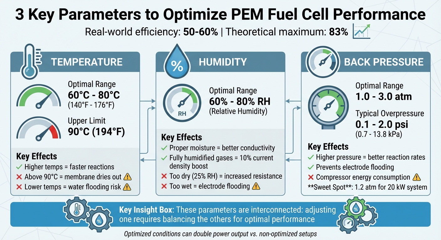
PEM Fuel Cell Optimization Parameters: Temperature, Humidity, and Back Pressure Ranges
Mass Transport Analysis of a Hydrogen PEM Fuel Cell COMSOL Tutorial

Key Parameters That Affect PEM Fuel Cell Performance
Three main factors shape the performance of a PEM fuel cell: operating temperature, relative humidity, and back pressure. These parameters are closely tied together - tweaking one often means adjusting the others to maintain optimal functionality. Among these, research highlights operating pressure as having the strongest influence on current density and gas distribution. For instance, increasing temperature can speed up reactions but also dries out the system, necessitating higher humidity and, in some cases, greater back pressure to keep reactants stable. Typically, PEM fuel cells operate between 60°C and 80°C (140°F to 176°F) and pressures from 1 to 3 atmospheres.
Operating Temperature
Temperature plays a direct role in how quickly hydrogen and oxygen react at the catalyst sites. Higher temperatures speed up these reactions and lower the activation over-potential, which is the extra voltage needed to kickstart the process. Operating at temperatures up to 80°C (176°F) can enhance efficiency by reducing this barrier.
That said, there’s a clear upper limit. Operating above 90°C (194°F) causes water in the membrane to evaporate faster than it can be replaced, leading to a sharp performance drop. As Colleen Spiegel notes:
"The upper limit of operation for PEMFCs is approximately 90 ºC because water evaporates from the membrane which dries the membrane out and causes the performance to drop quickly".
On the flip side, operating at lower temperatures slows reaction rates and risks water flooding the pores, blocking reactant gases from reaching the catalyst. Additionally, excessive heat can damage the membrane and speed up corrosion, shortening the cell’s lifespan. The challenge lies in striking a balance - temperatures high enough to boost efficiency but low enough to maintain moisture levels. This means precise humidity control is critical to avoid drying out the membrane.
Relative Humidity
The proton-conducting membrane, often made of PFSA materials like Nafion, depends on adequate water content for effective conductivity. This makes relative humidity (RH) a key factor. When RH drops from 100% to 25%, the membrane’s resistance increases, and reactions at the electrodes slow significantly.
Water movement in the membrane occurs in two ways: electro-osmotic drag (from anode to cathode) and back diffusion (from cathode to anode). Balancing these processes is essential to prevent the anode from drying out and to avoid flooding at the cathode. Fully humidified gases have been shown to improve current density by about 10% compared to dry conditions.
"Inadequate liquid water content in membrane, drying, may cause resistance on ion transport in the membrane... On the other hand, too much water or flooding causes flooding in flow field and GDL, which inhibits mass transport onto the electrode surface." – Journal of Industrial and Engineering Chemistry
At higher current densities (around 1.0 A/cm²), the ideal cathode RH typically ranges from 60% to 80%. This ensures the membrane stays hydrated without blocking gas pathways. Interestingly, increasing RH often has a more noticeable impact on efficiency than raising temperature, as the membrane’s ionic conductivity is highly moisture-sensitive. If humidity alone isn’t enough to maintain reactant flow, back pressure adjustments come into play.
Back Pressure
Back pressure refers to the pressure maintained on both the anode and cathode sides of the fuel cell. Increasing back pressure raises the partial pressures of hydrogen and oxygen, enhancing reaction rates as described by the Nernst equation. Even systems described as "atmospheric pressure" typically operate with a slight overpressure - ranging from 0.1 to 2.0 psi (0.7 to 13.8 kPa) - to drive gases through flow channels and remove water byproducts.
Higher back pressure reduces mass transport losses by keeping reactant concentrations near the catalyst sites high, especially during high-power operations. It also aids water management by pushing liquid droplets out of gas diffusion layers, preventing electrode flooding. Simulation studies have shown that raising pressure from 1 atm to 4 atm can significantly boost current density.
However, compressing gases consumes energy, which can offset efficiency gains. It’s crucial to ensure the voltage improvements from higher pressure outweigh the energy used by compressors. Additionally, maintaining equal pressures on the anode and cathode sides helps avoid mechanical stress on the membrane. Back pressure becomes even more critical at higher temperatures (80°C to 120°C or 176°F to 248°F), where it sustains sufficient oxygen partial pressure despite increased water vapor levels.
How to Optimize PEM Fuel Cell Parameters
Improving PEM fuel cell performance involves fine-tuning key parameters like temperature, humidity, and back pressure. By implementing dynamic control systems, these adjustments can be made in real time to match varying loads, ensuring efficiency across the entire operating range instead of relying on static settings.
Adjusting Operating Temperature
Temperature management starts with a reliable thermal system to handle the heat generated during reactions. Cooling units equipped with specialized coolants and temperature sensors at cell outlets are commonly used for this purpose. For instance, a 2017 study on a 2.4 kW PEM fuel cell showed that using 0.5 vol% ZnO nanofluids improved cooling capacity by 29%, allowing for a 27% reduction in radiator size while maintaining performance.
Dynamic temperature control is essential. At higher loads, raising temperatures (up to 80°C or 176°F) enhances reaction kinetics, but it’s crucial to monitor membrane hydration to prevent damage. During start-up, lower temperatures minimize warm-up times and reduce stress on stack components. Proper humidity control also plays a significant role in maintaining membrane conductivity.
Controlling Humidity Levels
Traditional humidifiers often struggle to respond quickly to load changes. A more precise approach involves mixing dry and saturated gas streams in real time, using PI or PID control algorithms with continuous feedback from humidity sensors. This method allows for accurate relative humidity control, ranging from 2% to 100%. In environments with high humidity (above 80% RH), "warmed probe technology" can prevent condensation by heating the sensor element above ambient temperature.
Anode recirculation is another practical method, where unreacted, humid fuel from the anode outlet is redirected back to the inlet, passively humidifying the incoming gas stream. For applications where external humidifiers add too much weight or bulk, self-humidifying membranes integrated with Pt nanoparticles and hygroscopic materials like SiO₂, TiO₂, or zeolites offer a compact solution. For example, Toyota's MIRAI fuel cell vehicle achieved a 13 kg weight reduction and saved 15 L of space by adopting self-humidifying technology. Additionally, operating at lower temperatures (around 60°C or 140°F) reduces the drying effect of reactant gases. At this temperature, the drying capacity is only about 30% of what it would be at 80°C.
Setting Back Pressure
Once temperature and humidity are optimized, adjusting back pressure can further enhance system performance. This involves finding a balance between boosting the fuel cell stack’s output and minimizing the power consumed by the air compressor. A 2017 study on a 20 kW vehicular PEM fuel cell system found that while higher pressure improved stack power, the best overall system performance occurred at 1.2 atm, accounting for compressor energy use.
Similarly, a 2020 study on a 30 kW stack (96 cells, 409 cm² area) revealed that maximum efficiency was achieved at 55.21% during the lowest continuous load and 43.74% at the highest, with optimized pressure and flow. During high-load demands, increasing back pressure (up to pressure ratios of 1.67) can boost power, while reducing it during low loads minimizes compressor losses. Pressure sensors at both anode and cathode inlets and outlets are essential for maintaining balance and protecting the membrane. Using a two-speed compressor can also cut power consumption while maintaining necessary pressure levels. For systems operating at intermediate temperatures above 80°C (176°F), pressurization helps offset the reduced oxygen partial pressure.
sbb-itb-501186b
Measuring Performance Improvements
Once you've optimized temperature, humidity, and back pressure, the next step is to collect quantitative data to confirm whether these adjustments lead to better performance. This data not only validates your efforts but also provides a clear comparison between the optimized setup and the baseline conditions. A widely used tool for this purpose is the polarization curve, which illustrates how cell voltage changes with varying current densities. By comparing these curves, you can directly measure the impact of your optimizations on performance.
Using Polarization Curves
Polarization curves are incredibly insightful because they highlight improvements across three key regions: activation, ohmic, and concentration. Here's what each region reveals:
- Activation Region (low current densities): This is where you can see gains in catalyst efficiency and reaction kinetics.
- Ohmic Region (moderate current densities): Improvements here often stem from reduced internal resistance, which can result from better membrane hydration or enhanced contact between components.
- Concentration Region (high current densities): This area reflects how well mass transport and gas diffusion have been optimized.
"The standard measure of performance for fuel cell systems is the polarization curve, which represents the cell voltage behavior against operating current density."
– Colleen Spiegel, The Fuel Cell Blog
To ensure accuracy, take measurements after 15 minutes of stable operation at each load step, averaging the final five minutes. This allows the cell to reach thermal and water balance equilibrium. Running tests while both increasing and decreasing the current can also help identify hysteresis effects.
For example, in March 2025, General Motors LLC researchers fine-tuned eight parameters - including pressure, temperature, and catalyst loading - on a hydrogen PEM fuel cell stack. Their efforts resulted in a cell voltage of 0.67 V, 51 kW stack power, and 57% efficiency, surpassing the baseline conditions of 77°F and 1 atm. Similarly, ElectroChem Inc. developed a "maximum performance polarization curve" for a 50 cm² serpentine flow field cell by dynamically adjusting stoichiometry, humidity, and temperature during testing. This approach doubled the power output compared to a fixed-condition baseline.
Analyzing Power Density and Efficiency
After reviewing the polarization curves, shift your focus to power density and efficiency to evaluate overall system performance. These metrics provide a broader perspective on the effectiveness of your optimizations. For instance, measuring stack efficiency and net system power - which accounts for parasitic loads like compressors and cooling pumps - offers a complete picture of performance. Keep in mind that while higher operating pressures can enhance stack performance, they might reduce net system efficiency if auxiliary power consumption rises significantly.
Hydrogen utilization is another critical metric. It measures the percentage of hydrogen that reacts within the system. In a March 2025 study, researchers fine-tuned purge valve actuation in an ejector-based PEM system, increasing hydrogen utilization by 0.79 percentage points to 98.2% and improving system efficiency by 0.72 percentage points to 47.21% (based on higher heating value). To pinpoint mass transport issues, you can replace air with pure oxygen during testing. If the potential difference between the two increases at high current densities, it signals lingering mass transport challenges.
| Metric | Indicator | Where to Look |
|---|---|---|
| Cell Voltage | Overall health and efficiency | All current density regions |
| Activation Loss | Catalyst effectiveness | Low current density |
| Ohmic Loss | Internal resistance (e.g., membrane hydration, component contact) | Moderate current density |
| Concentration Loss | Mass transport and gas diffusion | High current density |
| Hydrogen Utilization | Fuel economy and overall system efficiency | System-level operation |
Conclusion
Getting the most out of a PEM fuel cell comes down to carefully managing three key parameters: temperature, humidity, and pressure. Each one has a unique role in driving efficiency. Temperature influences reaction speeds, humidity keeps ionic conductivity in check, and pressure increases reactant concentration - though it can also raise parasitic power demands. When these elements are fine-tuned, performance can improve dramatically. In fact, research has shown that optimized conditions can double power output compared to non-optimized setups.
Real-time adjustments based on current density allow the fuel cell to operate along its maximum performance polarization curve, avoiding the inefficiencies of settling for average results. These fine-tuned adjustments not only boost immediate power output but also contribute to the system's durability over time.
"Using the correct operating condition for each parameter is critical to obtain good fuel cell performance."
– Colleen Spiegel, Fuel Cell Store
Beyond improving power output, proper optimization also reduces costs and enhances long-term reliability. By controlling these parameters, you can prevent issues like membrane degradation and excess fuel consumption. This approach aligns with the U.S. Department of Energy's lifetime targets of 5,000 hours for mobile applications and 40,000 hours for stationary systems. Under optimized conditions, PEM fuel cells have been shown to achieve efficiencies of 57% and stack power outputs as high as 51 kW.
To get the best results, make small, incremental adjustments to temperature, humidity, and pressure. Use polarization curves and efficiency metrics to monitor progress. This data-driven strategy ensures your PEM fuel cell performs at its peak while maintaining a longer operational life.
FAQs
How does temperature impact the performance of PEM fuel cells?
Temperature is a key factor in how well proton exchange membrane (PEM) fuel cells operate. Running these cells at higher temperatures generally boosts reaction speeds, lowers activation losses, and increases efficiency. Plus, higher temperatures aid in water vaporization, which helps manage water levels and keeps the system running smoothly.
That said, PEM fuel cells perform best within a specific temperature range. Going beyond this range can hurt performance, potentially causing damage or shortening the system's lifespan. Striking the right temperature balance is essential for ensuring both efficiency and long-term reliability.
Why is maintaining proper humidity important for PEM fuel cell performance?
Proper humidity control plays a key role in ensuring proton exchange membrane (PEM) fuel cells perform effectively. When the membrane dries out, its ability to conduct protons diminishes, which increases resistance and lowers efficiency. Conversely, too much moisture can lead to water buildup - also known as flooding - which obstructs reactant flow and limits the cell's power output.
Maintaining the right humidity balance is critical for achieving efficient operation, consistent power delivery, and long-term durability of the fuel cell.
How does back pressure affect the performance of PEM fuel cells?
Back pressure is an important factor in improving the performance of proton exchange membrane (PEM) fuel cells. When back pressure is increased, it enhances hydrogen diffusion through the gas diffusion layer, allowing better interaction with the catalyst surface. This leads to higher cell voltage and greater overall power output.
Getting the back pressure just right is critical for efficiency. It helps ensure an even flow of reactants and avoids performance drops caused by uneven gas distribution. However, excessive back pressure can lead to higher energy consumption, so fine-tuning is essential to strike the right balance.


