Step-by-Step Transformer Installation Guide
Installing a transformer is more than just connecting wires. It involves careful planning, safety protocols, and adherence to regulations like NEC Article 450. Improper installation can lead to overheating, fires, electric shock, or equipment failure. This guide walks you through each stage, from site preparation to final testing, ensuring a safe and efficient process. Here's what you'll learn:
- Site Preparation: Choose a location with proper ventilation, clearance, and a stable foundation.
- Inspection: Verify nameplate data, check for shipping damage, and ensure compatibility with project specs.
- Foundation & Mounting: Build a reinforced concrete pad and secure the transformer to prevent movement or stress.
- Wiring & Grounding: Use proper connections, torque specifications, and grounding techniques to ensure safety and performance.
- Testing & Energization: Perform insulation resistance tests, monitor for voltage imbalances, and gradually apply load.
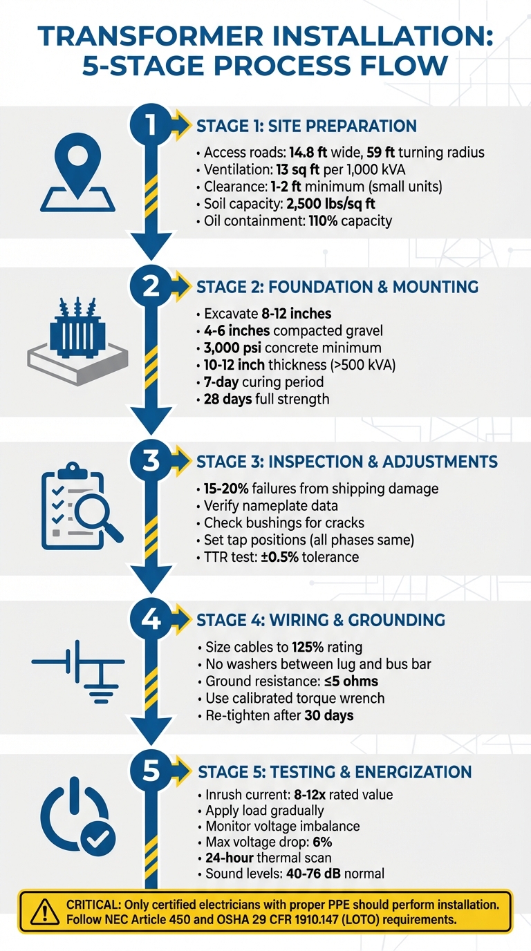
5-Stage Transformer Installation Process: From Site Prep to Final Testing
INSTALL: Single Phase Transformer #journeyman #linelife #lineman
sbb-itb-501186b
Site Preparation and Initial Checks
Before positioning a transformer, it's critical to ensure the installation site meets all necessary standards. A poorly chosen location or an inadequate foundation can lead to overheating, early failure, or even safety risks. Both the physical site and the transformer's specifications must align to ensure proper operation and safety.
Choosing the Installation Site
Finding the right location means considering factors like accessibility, ventilation, structural stability, and environmental conditions. For instance, access roads must be at least 14.8 feet wide and have a turning radius of at least 59 feet to accommodate heavy trailers. Cranes and other lifting equipment also need sufficient overhead clearance and stable ground to operate safely.
Ventilation is especially important for dry-type transformers. Indoor setups typically require ventilation duct areas of about 13 square feet per 1,000 kVA, with airflow rates of around 10,600 cubic feet per minute per MVA. Avoid placing transformers near walls or in corners to prevent heat buildup and avoid the "megaphone effect". Maintain at least 1 to 2 feet of clearance on all sides for smaller transformers, increasing the spacing for larger or high-voltage units.
Other site considerations include flood risks and exposure to corrosive elements. For liquid-filled transformers, an oil containment system capable of holding 110% of the oil capacity is essential. Additionally, foundation plinths should be elevated 12 to 24 inches above ground level to prevent water pooling.
The soil must be able to support the transformer's weight without settling. Typically, soil should handle a bearing pressure of 2,500 pounds per square foot. For transformers rated at 2,000 kVA or more, a professional soil analysis is recommended to confirm the ground can handle the load. In areas prone to earthquakes, lateral bracing and solid anchorage are necessary to account for the transformer's high center of gravity.
| Transformer Rating | Min. Side Clearance | Front/Rear Clearance | Between Units |
|---|---|---|---|
| ≤1,000 kVA (Outdoor) | 3.9 ft | 4.9–6.6 ft | 6.6 ft |
| 1,000–5,000 kVA | 4.9 ft | 8.2 ft | 8.2–9.8 ft |
| >5,000 kVA or 132 kV+ | 8.2–9.8 ft | 9.8–13.1 ft | 11.5–16.4 ft |
Once the site is prepared, confirm that the transformer’s specifications match the conditions of the environment.
Checking Transformer Specifications
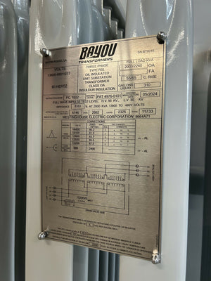
After ensuring the site is ready, the next step is to verify the transformer's specifications. Start by reviewing the nameplate data to confirm it matches the project requirements for kVA rating, voltage, phase, frequency, and impedance. As Mike Holt, the owner of Mike Holt Enterprises, explains:
A transformer that's marked as 480V primary, 208V secondary can't be wired with a 208V primary and 480V secondary. According to UL 1561, only transformers marked in this manner can be installed this way.
Additionally, check that the insulation class and enclosure rating are suitable for the site's humidity, dust, and exposure to corrosive substances. NEC Article 450 mandates that dry-type transformers must include the insulation system's temperature class on the nameplate. Pay close attention to the "Required Clearances" listed on the nameplate, as they are essential for safe operation.
Inspect the transformer for any shipping damage, such as dents, cracked insulators, or loose connections, as these can compromise safety. For liquid-filled transformers, maintain positive gas pressure at all times - even in low temperatures - to prevent contamination. Before positioning the unit, clean the transformer room and cable trenches to remove dust and debris.
Finally, ensure that a primary disconnect is visible and located within 50 feet of the transformer. If the disconnect is farther away, it must be clearly marked on the transformer and lockable, as required by the NEC. This step is crucial for both safety and accessibility.
Foundation and Mounting
After verifying the site, the next step is ensuring a solid foundation. A stable base is essential to avoid settling or cracking, which can lead to mechanical stress on the transformer's internal components. A properly constructed foundation helps the unit operate safely and reliably for years.
Preparing the Foundation
Begin by excavating 8–12 inches, depending on the soil conditions. Make sure the excavation extends beyond the transformer's footprint to provide space for formwork. Add 4–6 inches of compacted gravel or crushed stone to improve drainage and stability.
Set up forms and reinforce the pad with steel rebar or wire mesh. Use a concrete mix rated at a minimum of 3,000 psi. For transformers rated above 500 kVA, increase the pad thickness to 10–12 inches.
Before pouring the concrete, verify that all conduit stub-ups are correctly aligned with the transformer's input and output terminals. Misaligned conduits at this stage can lead to expensive delays. After pouring, smooth the surface with a 1/8-inch-per-foot slope to allow for proper water runoff.
Keep the concrete moist for at least seven days by covering it with wet burlap or plastic sheeting. Although the concrete reaches full strength in 28 days, it can typically support the transformer after the initial curing period. Skipping or rushing this curing process can result in cracks or uneven settling.
| Transformer Capacity | Recommended Pad Dimensions | Recommended Thickness |
|---|---|---|
| 75 kVA – 500 kVA | 5.5 ft × 6.5 ft | 10 in |
| 500 kVA – 2,500 kVA | 8.0 ft × 9.0 ft | 10 in |
| Small Residential | 4.0 ft × 6.0 ft | 6 – 8 in |
Mounting the Transformer
Once the pad has cured, confirm that it is level before placing the transformer. Use a spirit level to ensure there are no uneven surfaces, as even slight tilting can create internal stress. For transformers under 100 kVA, a forklift is usually sufficient for positioning. Larger units, however, will require a crane or specialized rigging equipment. Always use the manufacturer's designated lifting eyes for safe handling.
Position the transformer with its input and output terminals oriented for straightforward cable routing. Adequate clearance is crucial during mounting to ensure proper ventilation and prevent heat buildup. Avoid placing the transformer near walls or obstructions that could hinder airflow and shorten its lifespan.
For indoor floor-mounted units, install vibration-dampening pads between the transformer base and the floor. These pads help minimize noise and prevent vibrations from affecting the building structure. Once the transformer is in place, secure it to the foundation using the manufacturer's recommended hardware. In areas prone to earthquakes, use specialized anchoring systems to prevent movement during seismic events.
With the transformer securely mounted, the next step is to carry out pre-installation inspections and adjustments.
Pre-Installation Inspection and Adjustments
Before connecting a transformer electrically, it's crucial to perform a thorough inspection while it's mounted. Surprisingly, about 15–20% of early transformer failures are linked to shipping damage, improper storage, or installation mistakes - not manufacturing defects. Identifying these problems early can save you from expensive downtime. Below, you'll find detailed steps for inspection, tap adjustments, and safety protocols.
Unpacking and Initial Inspection
Start by inspecting the transformer as soon as it’s delivered. Document any visible transit damage before unloading. Look for dents, paint scrapes, or signs of load shifting on the enclosure. Pay close attention to porcelain bushings and insulators - use angled lighting to spot micro-cracks. Cooling fins also need a careful check; dents over 5 mm can restrict airflow. Additionally, check shock or tilt indicators to see if the unit experienced excessive G-forces during transit. For liquid-filled transformers, confirm the oil level on the magnetic oil level gauge and check that the humidity indicator cards are blue (acceptable moisture levels) rather than pink.
Cross-check the nameplate data with the shipment details. Verify the kVA rating, primary and secondary voltages, phase, frequency, and impedance. If external damage is evident, inspect internal components for potential shipping-related issues. Always ground the transformer tank permanently before conducting any detailed internal inspections.
| Component | Inspection Point | Accept/Reject Criteria |
|---|---|---|
| HV/LV Bushings | Porcelain surface | No chips, cracks, or glaze damage |
| Radiators/Fins | Physical alignment | No crushing greater than 5 mm |
| Valves | Cap presence | All caps installed; no oil weep |
| Pressure Relief | Disc position | Seated with no rupture indication |
| Tank Seams | Weld appearance | No visible cracks or seepage |
| Humidity Card | Color indicator | Blue (acceptable) / Pink (remediate) |
Inspection criteria based on.
Once you’ve documented any physical damage, you can move on to adjusting the taps.
Setting Tap Adjustments
After confirming the transformer is free from shipping damage, ensure it’s de-energized and verify this with a voltage tester. Clean tap contacts by removing protective coatings, then apply a thin layer of electrical compound to prevent oxidation. When selecting a tap, choose above 100% for high incoming voltage and below 100% for low voltage. Ensure all phases are set to the same tap position - misaligned settings can cause circulating currents, which reduce equipment lifespan. Use a calibrated torque wrench to tighten all bolted tap connections to the manufacturer’s specifications.
After setting the taps, conduct a Transformer Turns Ratio (TTR) test to confirm that the ratio matches the nameplate. The measured ratio must fall within ±0.5% of the rated value. Additionally, perform a DC winding resistance test to check for loose joints or improper contact seating.
Safety Procedures
Once the inspection and tap adjustments are complete, follow lockout/tagout procedures before making any further adjustments or internal inspections. During testing, lethal voltages may be present, so ensure all personnel are fully aware of the risks. Insulate any unused taps to prevent accidental contact. Keep a detailed inventory of all tools and hardware used during the inspection to ensure nothing is left inside the tank or enclosure, which could lead to failures after the transformer is energized. If the transformer needs to be stored after unpacking but before installation, seal all ventilation openings and shield the unit from moisture and contaminants to prevent damage.
Wiring, Connections, and Grounding
Once inspections and adjustments are complete, the next step is to establish secure and reliable electrical connections.
Routing and Connecting Wires
Carefully route cables through designated access holes, keeping them away from transformer coils and top blades to avoid heat damage. Properly support the cables to minimize mechanical stress and prevent connection failures. Refer to the manufacturer's nameplate diagram for primary and secondary connections - it provides essential details on voltage arrangements and tap settings. For added safety, many consulting engineers suggest sizing cables to 125% of the transformer's nameplate rating.
When making connections, use UL-listed mechanical or compression-type lugs that are appropriately sized. Do not place washers between the terminal lug and the bus bar, as this increases impedance and can cause overheating. If aluminum conductors are used, apply a protective compound to prevent oxidation, but ensure the factory-applied terminal plating remains intact. For separately derived systems, bond the neutral-to-case (X0 terminal) at only one location - either at the source or the first disconnecting means. This avoids creating parallel paths for neutral current.
Grounding the Transformer
After routing the cables, proper grounding becomes essential for safety. NEC 450.10(A) requires dry-type transformers to use a terminal bar for grounding and bonding conductors. Additionally, all metal enclosures and supports must be bonded to create a low-resistance earth path. This path stabilizes the voltage and provides a safe route for fault currents. A well-grounded system should have a resistance of 5 ohms or less. Use NEC Table 250.66 to determine the minimum sizes for grounding conductors; in many industrial setups, 4 AWG copper is commonly used.
"The grounding electrode conductor must connect directly to the grounded neutral conductor terminal. It can't be terminated to the case of the transformer." - Mike Holt
Before installing ground rods, assess soil conditions. In areas with high soil resistivity, consider using conductive back-fill materials like bentonite or installing multiple ground rods to meet the resistance requirement. Once installed, verify the grounding resistance using fall-of-potential or clamp-on resistance tests to ensure it stays below 5 ohms.
Torque Requirements for Terminals
For all bolted connections, use a calibrated torque wrench and follow the manufacturer's torque specifications. Incorrect torque can lead to high-resistance connections, overheating, and potential failures. After tightening bolts initially, wait one minute and re-tighten to the specified torque value. Additionally, revisit and re-tighten all cable retaining bolts after 30 days to account for settling and thermal cycling.
| Bolt Size (Inches) | Torque (Foot-Pounds) |
|---|---|
| 1/4 | 20 |
| 5/16 | 25 |
| 3/8 | 35 |
| 1/2 | 75 |
| 5/8 | 110 |
These torque values apply to steel nuts and bolts.
Energizing, Load Connection, and Final Testing
Energizing the Transformer
Before powering up the transformer, ensure all internal checks have been thoroughly completed. This step is crucial to avoid potential issues. Only certified electricians wearing proper PPE - such as arc-rated clothing, insulated gloves, and face shields in line with NFPA 70E guidelines - should handle this process. Additionally, implement strict Lockout/Tagout (LOTO) procedures, as outlined by OSHA 29 CFR 1910.147, to prevent accidental re-energization. Perform a final inspection to clear the transformer enclosure of any tools, spare parts, or shipping braces.
For oil-filled transformers, confirm that the insulating fluid has a dielectric strength of at least 26 kV and a temperature above –20°C (–4°F). Check silica gel breathers - if they appear pink, they are moisture-saturated and must be replaced. Begin by energizing the transformer without connecting the load. Monitor the secondary voltages, ensuring they are balanced and consistent for both line-to-line and line-to-ground measurements. Any significant imbalance warrants immediate de-energization and further diagnosis.
"When safety precautions are not met, system breakdown, emergency shutdown, and injury can result, each of which can place your operations in jeopardy." - Shreejee Electronics
Connecting and Testing the Load
Once the transformer is energized and stable, you can proceed to connect the load. Keep in mind that transformers experience an inrush current of 8–12 times their rated value. To manage this, gradually apply the load in steps while monitoring voltage and current. Use a thermal camera to identify any hotspots during this process. If the voltage drop exceeds 6% of the nominal value when the load is applied, the transformer may be overloaded and could require replacement.
Avoid measuring the output voltage directly at the transformer terminals while it is energized, as the high voltage poses serious risks. Instead, use a safer access point near the load. Should the load-side voltage be too low, adjust tap connections below 100% to increase it; if it’s too high, use tap connections above 100% to decrease it. Always adjust tap settings uniformly across all phases to maintain balance.
As the load is gradually applied and monitored, prepare for the final inspection and documentation phase.
Final Inspection and Documentation
After the transformer has operated at full load for 24 hours, conduct a thermal scan of the tank and bushing connections to identify any hotspots. For oil-filled transformers, take an oil sample to check for fault gases and establish a post-energization baseline. Additionally, listen for unusual sounds like loud buzzing, crackling, or popping, which might indicate internal problems. Normal sound levels for liquid-filled transformers range from 40 dB for units under 500 kVA to 76 dB for those up to 10,000 kVA.
Finally, document all test results, including voltage readings, tap settings, and thermal scan images. These records will serve as a critical reference for troubleshooting and regular maintenance throughout the transformer's lifespan.
Conclusion
Summary of Main Steps
Installing a transformer properly requires careful attention to detail throughout every phase. Start with site preparation by choosing a level, dry location and building a 3,000 psi reinforced foundation. Move on to inspection and mounting, ensuring the nameplate data aligns with the project specs, using designated lifting points, and adding vibration-dampening pads to minimize noise. During the electrical connections phase, precision is key: adjust taps correctly, use a calibrated torque wrench for bolted terminals, and ground the enclosure permanently in line with NEC standards. Finally, the testing and energization stage includes insulation resistance tests, energizing the transformer without a load initially, and gradually applying the load while checking for voltage imbalances.
These steps are essential for a safe and effective transformer installation.
"The successful operation of a transformer is dependent on proper installation as well as on good design and manufacture." - Morgan
Proper installation isn't just about equipment performance - it’s about protecting lives from dangerous voltages, ensuring warranties remain valid, and staying compliant with NEC Article 450. Skipping any of these steps can lead to equipment failure, void warranties, and compromise safety. Additionally, don’t overlook post-installation maintenance requirements.
Where to Source Transformers
Once the installation process is clear, the next step is securing high-quality equipment. Electrical Trader (https://electricaltrader.com) is a trusted source for both new and used transformers. Their inventory includes everything from 3-phase units to substation transformers, alongside a variety of power distribution equipment like breakers, voltage tools, and power generation products - all available in one convenient marketplace.
Whether you need standard models or specialized units, partnering with suppliers who stock ANSI/IEEE and NEMA-compliant transformers ensures your installation meets all testing and performance criteria. Using reliable components and hardware is key to achieving a long and dependable service life for your transformer.
FAQs
Do I need a soil test before installing a transformer?
A soil test isn't strictly necessary for installing a transformer. However, it's often part of site preparation to guarantee a stable foundation and ensure proper grounding - both of which are essential for safety and reliable performance. Always refer to the manufacturer's guidelines and local electrical codes to confirm specific requirements.
How do I know if my transformer tap setting is correct?
To ensure your transformer tap setting is accurate, start by checking that the secondary voltage aligns with the desired level after making adjustments. Use a dependable voltmeter to measure the voltage at the secondary terminals, and confirm that the readings fall within the range specified by the manufacturer.
Additionally, conduct standard tests such as ratio and polarity checks to verify the settings are correct. Make sure the transformer is properly grounded, and confirm that the voltage readings remain stable during the process.
What tests should be done before and after energizing a transformer?
Before energizing: It's essential to carry out a series of tests to ensure the transformer's safety and functionality. Start with insulation resistance tests and check the dielectric strength of the insulating fluid (which should measure at least 26 kV for new fluid). Conduct pressure tests to identify any potential leaks, inspect the unit for physical damage, and verify both the winding resistance and the winding ratios.
After energizing: Once the transformer is powered up, perform tests to confirm the voltage ratio, polarity, losses, and insulation integrity. Additionally, monitor the temperature limits and assess the condition of the oil. These steps are crucial for ensuring the transformer operates safely and reliably, minimizing the chances of failure.