
Dielectric Strength Testing for Power Distribution Systems
Dielectric strength testing ensures the safety and reliability of power distribution systems by evaluating the performance of insulation materials under high voltage. It helps prevent equipment failures, electrical hazards, and compliance issues with industry standards. Here's what you need to know:
- Purpose: Tests insulation's ability to withstand voltage without breakdown.
- Key Failures: Insulation can fail through puncture (breach of thickness) or flashover (surface arcing).
-
Types of Testing:
- AC Testing: Simulates conditions for equipment like transformers and motors.
- DC Testing: Ideal for cables and high-capacitance equipment.
- Standards: Guided by ASTM and IEC protocols to ensure consistent and safe practices.
- Importance: Identifies issues like aging, contamination, or defects before they cause outages or safety risks.
Dielectric testing is a proactive measure to maintain system integrity, reduce risks, and comply with safety standards.
Why Dielectric Strength Testing is Critical for Power Distribution Systems
Preventing Safety Hazards and Equipment Failures
Dielectric strength testing plays a crucial role in identifying weaknesses in insulation before they lead to serious problems. It highlights potential vulnerabilities in transformers, switchgear, and other high-voltage equipment, ensuring they can handle the electrical stresses they’ll face during operation. This testing is a key step in maintaining the safety and reliability of power distribution systems.
Insulation failures often stem from factors like aging, exposure to harsh environments, or manufacturing defects. These failures typically occur in two ways:
- Puncture: When the insulation’s thickness is compromised and breached.
- Flashover: When an electrical arc travels along the surface of the insulation.
Both scenarios can create immediate safety hazards and disrupt operations. Beyond safety, dielectric testing also serves as a quality control measure during manufacturing. It helps detect inconsistencies in materials early, allowing manufacturers to address any issues before the equipment is deployed.
Meeting Industry Standards
Industry standards ensure that dielectric strength testing is both consistent and reliable. These guidelines provide a structured approach for evaluating power distribution equipment. For instance, ASTM D149 outlines procedures for AC dielectric strength testing at commercial power frequencies (25 to 800 Hz), making it a go-to standard for routine quality checks. For equipment subjected to direct voltage stress, ASTM D3755 is used, as breakdown values under DC conditions are typically 2 to 4 times higher than those under AC.
Impulse testing, guided by ASTM D3426, is specifically designed to address transient voltage stresses, such as those caused by lightning strikes. This test simulates a lightning event using a 1.2/50‑μs wave, making it particularly valuable for outdoor equipment exposed to extreme weather conditions.
Adhering to these standards not only meets regulatory expectations but also ensures long-term equipment safety and performance. Additionally, compliance with both ASTM and IEC standards (60243‑1, 60243‑2, and 60243‑3) supports global trade by maintaining consistent safety and performance benchmarks across international markets.
Understanding High Potential Testing
Dielectric Strength Testing Methods
AC vs DC Dielectric Testing Methods Comparison
AC Testing vs. DC Testing
Dielectric strength tests are essential for confirming insulation reliability under both typical and extreme conditions, as outlined by industry standards. AC testing uses alternating current (50/60 Hz) to stress insulation at both polarities. This method mimics the operational environment of equipment like transformers, switchgear, and motors, making it particularly relevant for real-world performance. Typically, the test voltage is applied for one minute, though production-line standards sometimes allow for a shorter, one-second test by increasing the voltage by 20%.
On the other hand, DC testing employs a constant voltage, making it especially useful for equipment with high capacitance, such as long cables and motor windings. This approach minimizes capacitive charging currents, which can obscure actual leakage in AC tests. A key requirement for DC testing is a discharge period to safely eliminate stored charges, unlike AC testing, which naturally cycles to zero.
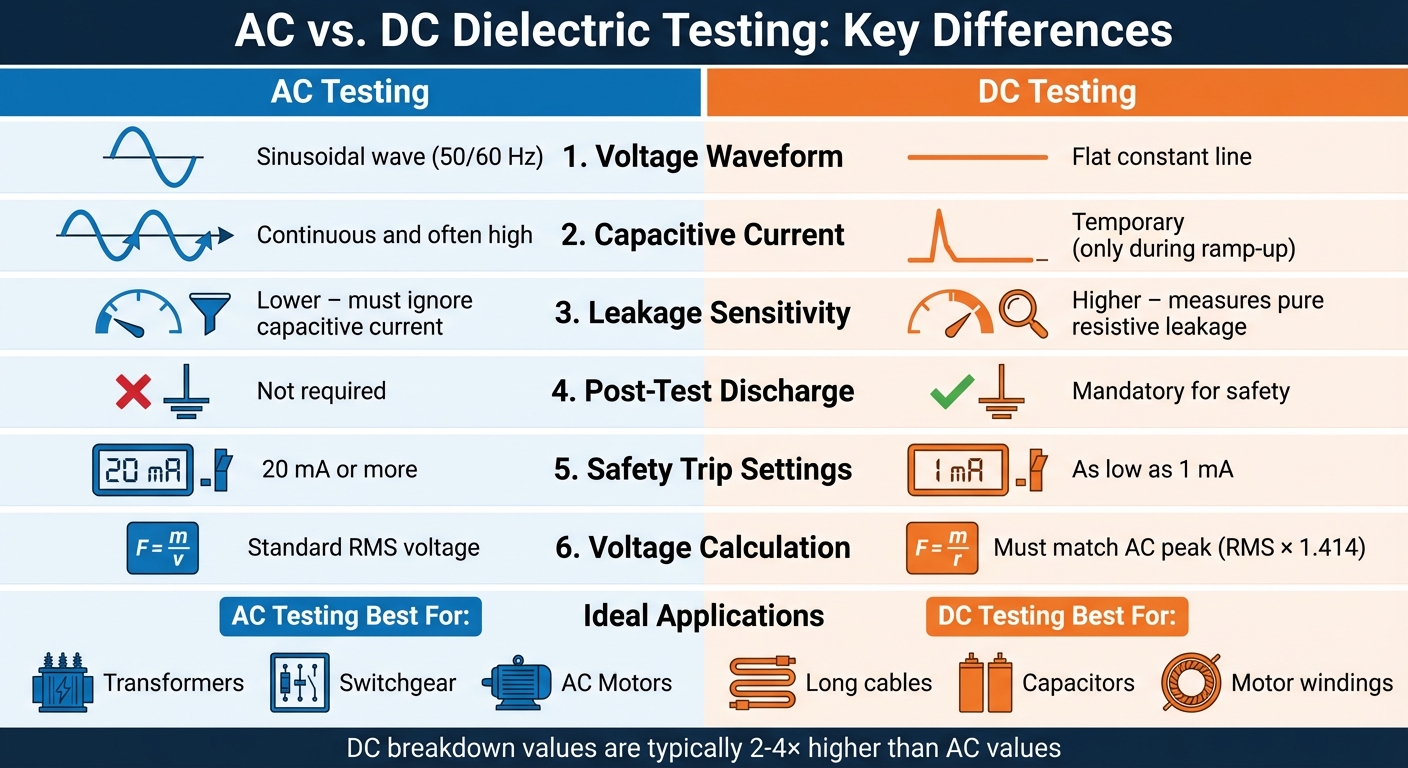
To ensure comparable stress levels, the DC voltage must match the AC peak value, calculated as RMS voltage multiplied by 1.414. DC testing also enhances operator safety by allowing for much lower current trip settings (as low as 1 mA), whereas AC testers require desensitization to 20 mA or more to account for normal capacitive charging currents.
| Feature | AC Dielectric Test | DC Dielectric Test |
|---|---|---|
| Voltage Waveform | Sinusoidal (50/60 Hz) | Constant Unidirectional |
| Capacitive Current | Continuous and often high | Temporary (only during ramp-up) |
| Leakage Sensitivity | Lower; must ignore capacitive current | Higher; measures pure resistive leakage |
| Post-Test Discharge | Not required | Mandatory for safety |
| Ideal Applications | Transformers, switchgear, AC motors | Long cables, capacitors, motor windings |
These methods provide the foundation for exploring specific testing procedures tailored to different types of equipment.
Testing Power Distribution Equipment
When applying dielectric strength tests, the approach varies depending on the equipment. For transformers and switchgear, AC testing is the go-to method as it simulates the alternating voltage stresses these devices face during regular operation. This test is particularly effective in identifying partial discharges - localized insulation breakdowns that, if left unchecked, could lead to full-scale failures.
Power cables, especially long underground ones, benefit greatly from DC testing. A real-world example highlights its importance: In December 2024, John Roberts, a seasoned electrical testing expert with 35 years of experience, conducted a high-voltage DC test on a long underground cable at an industrial site. Although the cable appeared visually intact, the test detected a gradual rise in leakage current over several minutes. This indicated moisture infiltration within the insulation - a problem that could have led to catastrophic failure. Thanks to this early detection, the facility was able to dry and recondition the cable, sidestepping significant downtime and costly repairs.
"High voltage dielectric tests help detect insulation weaknesses and prevent unexpected failures that could result in costly outages or safety hazards." - John Roberts, Professional Electrical Testing Expert, HVTestTech
For circuit breakers, AC tests are typically performed at 1.5 to 2 times their rated working voltage. In contrast, DC withstand tests require higher voltages, ranging from 2 to 3 times the rated voltage. These tailored approaches ensure that each piece of equipment is thoroughly evaluated for insulation integrity and reliability under operational conditions.
sbb-itb-501186b
Equipment and Procedures for Testing
Required Testing Equipment
Reliable dielectric strength testing starts with having the right tools. These tests need specialized equipment capable of generating and monitoring high voltages. High-voltage power supplies are a must. For transformers and switchgear, AC test sets operating at 50/60 Hz are commonly used. DC high-potential (Hipot) testers work best for cables and capacitive equipment, while impulse voltage generators simulate lightning strikes. Depending on the application, these power supplies can deliver voltages ranging from 500 V to as high as 30 kV.
Monitoring instruments are equally important. Leakage current meters help detect insulation deterioration during DC tests, while partial discharge detectors pinpoint weak spots during AC tests. Current-sensing elements are also critical - they automatically stop the test if insulation breakdown occurs, ensuring safety for both personnel and equipment. Safety gear, including grounding rods, leads, insulating gloves, boots, and face shields, is non-negotiable for every test.
Electrodes are used to apply the electric field to the insulating material, and their setup can significantly impact breakdown voltage readings, especially in uneven fields. Additional equipment like transformer oil testers, cable fault locators, and insulation resistance testers may also be required based on the specific testing scenario.
Testing Procedures Step-by-Step
Once the equipment is ready, follow these steps to ensure accurate and safe testing. Before powering up any test equipment, make sure the device being tested is fully de-energized and grounded to discharge any residual voltage. Personnel must wear the proper protective gear, and all insulation surfaces should be cleaned to avoid contamination that could lead to false test failures. In humid conditions, drying the equipment thoroughly is essential, as moisture can reduce dielectric strength and cause premature breakdowns.
Voltage application during testing adheres to one of three methods outlined in ASTM D149:
- Method A (Short-Time): Commonly used for quality control purposes.
- Method B (Step-by-Step): Ideal for comparing different materials.
- Method C (Slow Rate-of-Rise): A simpler option when motor-driven voltage controls are available.
For all methods, voltage should be increased gradually. In AC withstand tests, the voltage typically reaches 2–3 times the rated operating voltage, while DC tests for cables use 1.5–2 times the rated voltage. Once the target voltage is reached, it is held steady for one minute in AC tests.
During the test, technicians keep an eye out for leakage current spikes, arcing, or partial discharges. In DC testing, a slow increase in leakage current can indicate moisture or insulation issues, even if no immediate breakdown occurs. After completing a DC test, the device must be carefully discharged to remove any dangerous residual voltage. Regular calibration of hipot testers is vital to ensure accurate readings of leakage current and trip thresholds. Enabling arc detection features can also help identify localized breakdowns that might otherwise go unnoticed.
"Applying too low a voltage may not stress the insulation adequately, potentially missing weak points. On the other hand, applying too high a voltage can unnecessarily damage the insulation." - John Roberts, Professional Electrical Testing Expert
Factors That Affect Test Results
Material Properties and Testing Conditions
Test results are influenced by more than just the procedures - they rely heavily on the properties of the materials being tested and the conditions under which the tests are conducted. For instance, specimen thickness plays a major role in determining breakdown voltage. Thicker specimens generally withstand higher voltages, but this also depends on the material's homogeneity. In materials that aren’t uniform, voltage stress distribution changes depending on whether alternating current (AC) or direct current (DC) is used. With AC, the stress aligns with capacitive impedance, while in DC, once steady state is reached, resistance becomes the dominant factor.
Temperature control is another critical factor for accurate testing. For insulating liquids tested in the field, temperatures need to stay between 68°F and 86°F (20°C to 30°C) to align with laboratory standards. Contaminants like moisture, dirt, and conductive particles can drastically lower breakdown voltage. Specifically, moisture sensitivity decreases when water concentration is below 60% of saturation at room temperature.
The electrode configuration and surrounding medium also affect the results. Testing can occur in various gaseous or liquid environments, which determines whether failure manifests as a puncture through the material or as a flashover along its surface. For insulating liquids with high viscosity (over 900 cSt at 104°F or 40°C), standard disk electrode methods aren’t validated. Additionally, DC breakdown values are generally 2 to 4 times higher than the root mean square value of a 60 Hz AC breakdown.
Grasping these factors is crucial for evaluating how insulation materials will perform under real-world stresses. By combining this understanding with standardized protocols, consistent and reliable results can be achieved.
Standards and Testing Protocols
Standardized protocols ensure that material properties and testing conditions are evaluated consistently. ASTM D149 is the primary standard for testing solid insulating materials at power frequencies ranging from 25 to 800 Hz. For DC voltage testing, ASTM D3755 is used, while ASTM D3426 governs impulse testing, simulating lightning strikes with a 1.2 by 50-μs wave. These ASTM standards have international counterparts in the IEC 243 series (IEC 243-1, 243-2, and 243-3), which are technically comparable.
The method of applying voltage also impacts the results. Method A (Short-Time Test) is ideal for quick quality checks, whereas Methods B (Step-by-Step) and C (Slow Rate-of-Rise) tend to produce lower, more conservative breakdown voltages, providing a clearer picture of material differences. Polarity must also be considered during impulse testing, especially with asymmetrical electrodes. Comparative tests should include both positive and negative polarity, ensuring the electrode with the higher gradient is made negative, as polarity can significantly influence breakdown voltage in asymmetrical fields.
Testing documentation needs to include details like the voltage method, rate-of-rise, specimen preparation, medium, temperature, and electrode types to ensure compliance and accuracy.
"The dielectric strength of a material will be the determining factor in the design of the apparatus in which it is to be used." - ASTM D149-20
Conclusion
Dielectric strength testing plays a crucial role in maintaining the safety and reliability of power distribution systems. By pushing insulation beyond typical operating conditions, this testing method helps uncover weaknesses before they can lead to serious issues like arcing, fire hazards, or unexpected outages. Such failures not only disrupt operations but can also put personnel at significant risk.
Adhering to ASTM standards, such as D149, D3755, and D3426, ensures consistent and dependable insulation performance. Proper preparation is key - cleaning, drying, and gradually applying voltage minimizes the risk of false positives and prevents unnecessary stress on healthy insulation. For essential power distribution equipment, testing every 3 to 5 years as part of routine maintenance is recommended. Additional tests should follow significant repairs or new installations.
Environmental factors also play a vital role in achieving accurate results. Field tests should be conducted within a temperature range of 68°F to 86°F, with careful monitoring of leakage currents and proper grounding. By combining standardized procedures with high-quality equipment, professionals can build a robust safeguard against insulation failures - protecting both critical infrastructure and the people who rely on it.
FAQs
What is the difference between AC and DC dielectric strength testing?
Dielectric strength testing is essential for evaluating the insulation in electrical equipment, and whether AC or DC voltage is used depends entirely on the specific application.
AC testing applies a sinusoidal voltage, typically at 60 Hz in the US, to mimic actual operating conditions. This method is particularly suited for testing transformers, power cables, and other equipment as they function under normal use.
DC testing, in contrast, uses a steady direct voltage, making it a popular choice for control and acceptance tests. It’s capable of assessing insulation at much higher breakdown voltages - often 2 to 4 times the RMS value of AC voltage. While DC testing is generally easier and safer to conduct, it doesn’t replicate the stresses of real-world operating conditions as accurately as AC testing.
Both approaches play a vital role in maintaining the safety and reliability of power distribution systems. The decision on which to use depends on the specific requirements of the equipment and the objectives of the test.
How often should power distribution equipment undergo dielectric strength testing?
Dielectric strength testing plays a key role in keeping power distribution equipment in good working order. This type of testing is usually carried out during routine maintenance or after major repairs. While the exact timing can vary based on manufacturer recommendations, industry standards, and the specific operating conditions of the equipment, a general rule of thumb is to conduct tests every 1 to 3 years.
By performing these tests regularly, you can spot insulation problems early - before they escalate into equipment failures or safety hazards. This proactive approach helps maintain the safety, reliability, and overall performance of your equipment.
What can impact the accuracy of dielectric strength testing results?
The results of dielectric strength testing can be affected by various factors, such as moisture, contaminants, or defects in the material being tested. External conditions, including temperature, the method used to apply voltage, and the material's thickness, also have a major impact on the accuracy of the test.
For dependable results, tests should be carried out in controlled environments while adhering to standardized procedures. Preparing the test sample and equipment carefully is another key step in reducing potential errors.


