
How to Test Electrical Equipment for Reliability
Testing electrical equipment ensures safety, reduces downtime, and saves costs. Failures often result from insulation breakdown, overheating, or loose connections. Regular testing identifies issues early, helps meet industry standards, and prevents costly repairs. Here's a quick overview of the key steps and tools:
- Common Causes of Failure: Insulation wear, overheating, and loose connections.
- Essential Tools: Digital multimeters, megohmmeters, power quality analyzers, and infrared cameras.
-
Testing Steps:
- Safety Preparation: De-energize equipment, follow Lockout/Tagout (LOTO), and use proper PPE.
- Visual Inspection: Check for signs of damage, overheating, or contamination.
- Basic Electrical Checks: Measure voltage and test continuity.
- Advanced Diagnostics: Perform insulation resistance tests, infrared scans, and calculate reliability metrics like MTBF and MTTR.
Proper maintenance and testing improve equipment reliability and ensure compliance with safety standards. Investing in the right tools and following a structured process can prevent unexpected failures.
Electrical Maintenance Training – Equipment Testing, Troubleshooting and Reliability by EFTI
Tools You Need for Reliability Testing
Finding the right tools for reliability testing can save you from expensive failures down the line. Did you know that nearly 48% of motor failures are due to electrical issues? Of these, 36% result from winding problems, and 12% stem from rotor issues. The right equipment can help pinpoint these problems early, before they spiral into larger, costlier repairs.
For starters, a digital multimeter (DMM) is crucial. It measures voltage, resistance, and current, making it perfect for spotting blown fuses and damaged circuits. Meanwhile, a megohmmeter uses high-voltage, low-current DC to check insulation resistance, helping you detect moisture, contamination, or aging in your systems. To gain a full picture of system health, power quality analyzers log dips, swells, and inrush currents across all three phases. These tools can range in price from $1,000 to over $8,000, depending on their capabilities. For live measurements, clamp-on ammeters measure current flow through magnetic fields, and non-contact thermometers safely identify overheating issues from a distance. Together, these tools create a solid foundation for more advanced testing.
Common Testing Tools and What They Do
Insulation resistance is highly temperature-sensitive - it halves with every 10°C (18°F) increase and doubles with every 10°C decrease. To ensure accuracy, IEEE standards require correcting all measurements to a consistent 40°C (104°F).
Tools like insulation multimeters combine the features of a True RMS digital multimeter with a megohmmeter. For example, the Fluke 15x7 series is ideal for troubleshooting motor systems and distribution equipment. If you're working with three-phase motors, a phase rotation meter is a must - it ensures the correct rotational direction, preventing mechanical damage when connecting to loads. For older or high-capacitance insulation systems, advanced testers can automatically calculate the Polarization Index (PI) and Dielectric Absorption Ratio (DAR) - two key resistance ratios that provide insight into insulation health over time. Knowing what each tool does helps you choose the right one for your specific needs.
How to Select the Right Tools
Choosing the right tools starts with understanding your equipment's voltage ratings and ensuring your tester can deliver at least 1mA of test current. For routine maintenance, tools rated for 500V or 1,000V are typically sufficient. However, higher-voltage systems, like switchgear or transmission cables, may require testers capable of handling 2,500V to 10,000V. As John Olobri, an Electrical and Industrial Engineer at AEMC Instruments, explains, IEEE recommends tools that can provide 1mA of test current and maintain the test voltage throughout the testing period for accurate results.
For modern insulation systems, look for a megohmmeter that can measure into the Tera Ohm range for added sensitivity. Large rotating machines, such as motors and pumps, benefit from testers with timed functions that calculate PI and DAR ratios, accounting for the equipment's inductive and capacitive characteristics. When working with transformers, opt for a megohmmeter equipped with a "Guard" (G) terminal. This feature filters out surface leakage currents, ensuring you're only measuring the insulation's integrity.
Safety should never take a backseat. Always ensure your tools include an automatic discharge function to safely clear any capacitive charge after testing high-voltage components. Instruments with live circuit warnings are also essential - they prevent testing if voltage is detected, reducing the risk of accidents. Lastly, verify that your test leads are rated for your system's voltage requirements. If you're sourcing tools from platforms like Electrical Trader, double-check that they meet your system's specific voltage and performance needs, whether you're working with new or used equipment.
How to Test Electrical Equipment: Step-by-Step
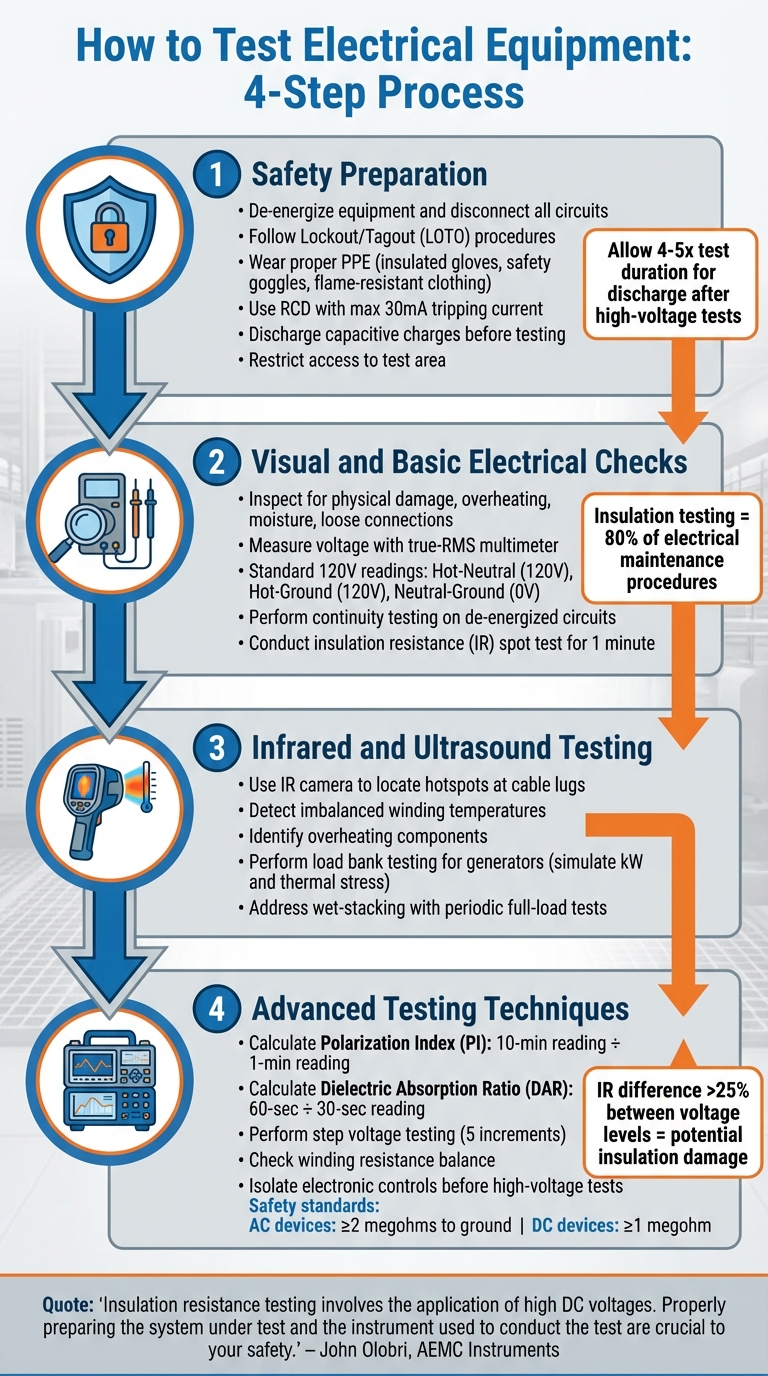
4-Step Process for Testing Electrical Equipment Reliability
Testing electrical equipment requires a careful, systematic approach to ensure safety and accuracy. By following these steps, you can conduct thorough and reliable assessments, starting with preparation and moving into advanced diagnostics.
Step 1: Safety Preparation
Begin with a risk assessment to identify potential hazards. De-energize the equipment by shutting it down, opening all switches, and disconnecting it from circuits, including neutral and protective ground connections. Follow Lockout/Tagout (LOTO) procedures to prevent accidental re-energization.
"Insulation resistance testing involves the application of high DC voltages. Properly preparing the system under test and the instrument used to conduct the test are crucial to your safety and help prevent damage to your wiring and machinery." – John Olobri, AEMC Instruments
Discharge any capacitive charges before conducting tests, especially during insulation resistance testing. Use the appropriate personal protective equipment (PPE), such as insulated gloves, safety goggles, and flame-resistant clothing. Evaluate and address any environmental hazards. Additionally, use an RCD (Residual Current Device) with a maximum 30mA tripping current as an extra safety measure. Restrict access to the test area and establish clear boundaries for energized work.
| Safety Measure | Description |
|---|---|
| LOTO | Lockout/Tagout to isolate all energy sources |
| Zero Energy Verification | Confirm zero energy using a calibrated meter |
| PPE | Wear insulated gloves, flame-resistant clothing, and eye protection |
| Discharge | Remove capacitive charges before and after high-voltage tests |
| Visual Inspection | Look for damage, leaks, or overheating signs |
| Site Security | Use barriers to keep unauthorized personnel away |
After performing high-voltage tests, allow the equipment to discharge for at least four to five times the test duration. Maintain clear communication with operations and security teams to avoid surprises during testing or changes in equipment status.
Step 2: Visual and Basic Electrical Checks
Inspect the area and equipment to identify potential issues. Look for physical damage, signs of overheating (such as discoloration), moisture, dirt, or loose connections. Then, use a true-RMS multimeter to measure voltage at receptacles. For a standard 120V circuit, typical readings include Hot-Neutral (120V), Hot-Ground (120V), and Neutral-Ground (0V). Be mindful of electrical noise caused by nearby equipment like fans or fluorescent lights, which can affect sensitive devices.
Perform continuity testing on de-energized circuits to ensure a complete current path and identify open circuits or broken wires. Use a ground impedance tester for precise wiring polarity checks instead of a basic three-lamp tester. If ground impedance values approach 0.25 ohms, it may indicate a loose connection that needs attention.
For insulation integrity, conduct an insulation resistance (IR) "spot test" by applying a test voltage for one minute to detect leakage or contamination. Insulation testing is a key part of electrical maintenance, often making up 80% of testing procedures.
Step 3: Infrared and Ultrasound Testing
Infrared (IR) thermography is an effective tool for identifying thermal issues that aren't visible to the naked eye. Use an IR camera to locate hotspots at cable lugs, detect imbalanced winding temperatures, and uncover overheating components in alternators or termination points. These thermal patterns can highlight loose connections, overloaded circuits, or failing parts before they cause major breakdowns.
For larger equipment like generators, load bank testing evaluates performance under real-world conditions, simulating kW and thermal stress. This can reveal cooling or control issues that may not be evident when the equipment is idle. It’s particularly useful for addressing wet-stacking, a problem caused by prolonged light loading. Running periodic full-load tests often resolves this issue. Combining load bank testing with infrared thermography provides a detailed picture of equipment behavior under stress.
Once thermal anomalies are identified, additional techniques can pinpoint underlying insulation problems.
Step 4: Advanced Testing Techniques
Advanced insulation testing methods, like the Polarization Index (PI) and Dielectric Absorption Ratio (DAR), offer deeper insights. The PI compares the 10-minute reading to the 1-minute reading, while the DAR compares readings at 60 and 30 seconds. These tests assess insulation cleanliness and moisture levels over time.
Step voltage testing applies increasing voltage levels (usually in five increments) to expose internal insulation weaknesses that might not appear at lower voltages. A difference greater than 25% between IR readings at different voltage levels signals potential insulation damage. Always isolate electronic controls and sensors before conducting high-voltage insulation tests, as these voltages can damage sensitive components.
Complement insulation tests with winding resistance balance checks to detect issues like phase-to-phase shorts or imbalances. For safe operation, ensure AC devices have at least 2 megohms to ground and DC devices at least 1 megohm. These advanced procedures complete the reliability assessment process, building on the earlier steps for a thorough evaluation.
sbb-itb-501186b
How to Interpret Test Results and Calculate Reliability
Interpreting reliability data is a key step in ensuring effective maintenance strategies. By breaking down test results and understanding reliability metrics, you can make informed decisions to optimize equipment performance and reduce downtime.
Calculating MTBF and MTTR
Mean Time Between Failures (MTBF) measures the average time between failures for systems that can be repaired during normal operation. To calculate it, divide the total operational hours by the number of failures. For instance, if a circuit breaker operates for 8,000 hours and fails four times, the MTBF is 2,000 hours. This metric is essential for planning maintenance schedules and predicting when equipment might fail.
"MTBF is a basic measure of a system's reliability; the higher the MTBF, the higher the reliability of a product." – Jonathan Trout, Noria Corporation
Mean Time to Repair (MTTR), on the other hand, calculates the average time needed to fix equipment after a failure. To find MTTR, sum all repair times and divide by the number of repairs. For example, if three repairs take 6, 4, and 8 hours, the MTTR is 6 hours. Keeping MTTR low minimizes downtime, which is critical for cost control. For equipment that cannot be repaired, Mean Time to Failure (MTTF) estimates the time until the first failure occurs.
When testing new equipment, you can determine the required test duration based on your MTBF goal and confidence level. For a 90% confidence level with zero failures allowed, multiply the MTBF target by 2.30. For example, verifying a 200-hour MTBF target requires 460 hours of testing. Testing multiple units simultaneously can save calendar time - ten units tested for 100 hours each provide 1,000 total test hours.
These calculations are vital for developing effective maintenance schedules and ensuring operational reliability.
Applying Reliability Data to Maintenance Planning
Reliability metrics like MTBF and MTTR directly impact maintenance planning. Use MTBF to schedule preventive maintenance before failures are likely to occur. Combine these metrics with data from infrared, insulation, and power quality tests to prioritize which equipment needs immediate attention and which can be monitored over time.
Power quality issues often signal hidden reliability risks. For example, voltage unbalance in three-phase systems can increase motor currents by 6 to 10 times the unbalance percentage, leading to overheating and premature failure. Similarly, voltage fluctuations of 10% or more, lasting from 0.5 cycles to 1 minute, can cause malfunctions like PLC lockups or contactor chatter. When such patterns appear, flag the affected equipment for urgent corrective action.
For critical assets like electric motors - which account for over 75% of an industrial facility's electrical energy use - tracking reliability data from the moment they're installed until they're retired is essential. Using tools like embossed metal tags with internal codes can help monitor failure trends and identify recurring issues. If repair times grow longer or failures become more frequent, replacing the equipment may be more cost-effective than continuing repairs.
Conclusion
Ensuring reliable electrical systems means combining structured testing, the right tools, and precise data analysis to avoid expensive downtime and safety hazards. Techniques like visual inspections, insulation resistance tests, infrared scans, and power quality analysis work together to give a full picture of equipment health.
"A regular program of resistance testing can detect insulation deterioration so it can be addressed before it becomes a major problem." – John Olobri, AEMC Instruments
Temperature correction is key for accurate comparisons. Insulation resistance values drop by half for every 10°C (18°F) increase in temperature. That’s why standardizing measurements to 68°F (20°C) is crucial for consistent and reliable trending.
Modern testing tools simplify the process. Devices that automatically calculate PI and DAR ratios, along with wireless data transfer and cloud storage, reduce manual errors and keep historical records accurate. These advanced methods strengthen your overall maintenance approach.
Whether you're upgrading your testing tools or replacing aging components flagged during reliability checks, platforms like Electrical Trader provide access to a wide range of equipment. From breakers and transformers to power generation tools, having the right gear ensures your systems run safely and efficiently for the long haul.
FAQs
What tools are essential for testing the reliability of electrical equipment?
To keep electrical equipment dependable, a few essential tools come into play. Insulation resistance testers, such as megohmmeters or hi-pot testers, are vital for checking the quality of insulation. By applying high voltage, these devices help spot potential problems early and reduce the risk of equipment failure.
Another must-have is a voltage tester, which confirms whether voltage is present - an important step for ensuring safety during any electrical work. On top of that, true-RMS multimeters are incredibly useful for precise voltage and continuity measurements, especially when testing branch circuits.
These tools work together to ensure electrical systems remain safe and reliable.
How do I accurately interpret insulation resistance test results?
To make sense of insulation resistance test results, focus on the resistance value, typically measured in megohms. This value gives you a snapshot of the insulation's condition. Higher resistance usually points to insulation in good shape, while lower resistance might suggest wear or even an impending failure. It's essential to compare your results against industry standards or the manufacturer’s guidelines, which specify the minimum acceptable resistance for particular equipment and voltage levels.
Keep in mind that factors like temperature and humidity can impact your readings. You may need to adjust for these conditions to get accurate results. Tracking resistance levels over time is equally important. A steady decline might indicate gradual wear, while a sudden drop could signal a more immediate concern. By testing regularly, you can catch potential problems early and ensure your equipment stays reliable.
Why should insulation resistance measurements be adjusted for temperature differences?
Insulation resistance varies with temperature, which can cause readings to be inaccurate if not accounted for. Adjusting measurements to a standard temperature ensures consistent and reliable evaluations of insulation over time. This practice helps detect potential problems early and supports the dependable performance of your electrical equipment.


