How to Choose Wiring for Hazardous Locations
When wiring for hazardous locations, safety is the top priority. These areas, prone to flammable gases, combustible dust, or ignitable fibers, require specialized systems to prevent explosions and fires. Key points to consider include:
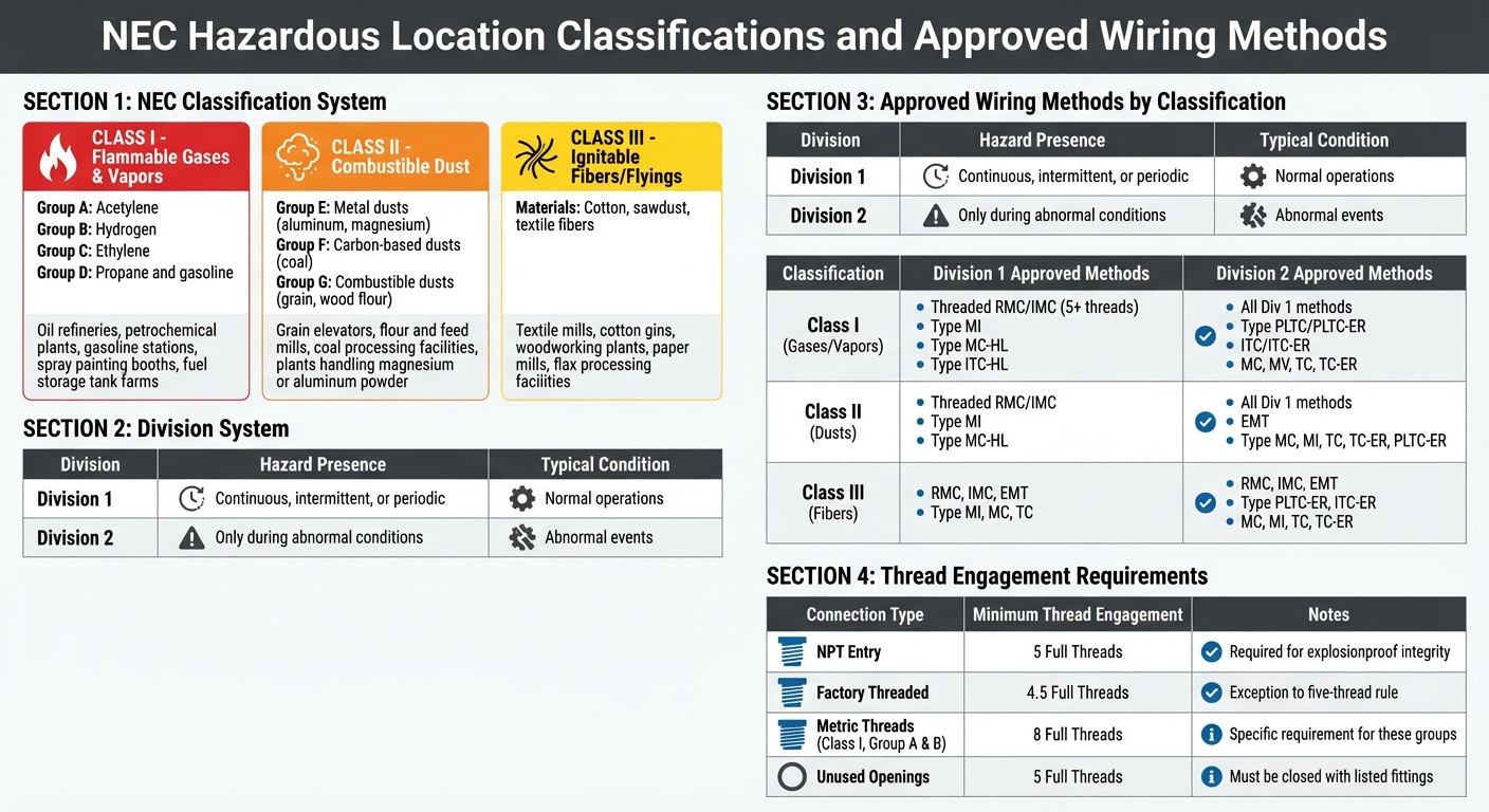
- Understand NEC Classifications: Hazardous areas are categorized into Classes (I, II, III) based on the type of hazard and Divisions (1, 2) based on the frequency of exposure.
- Follow NEC Standards: Use approved wiring methods like RMC, IMC, or specific cable types (e.g., MC-HL, TC-ER) tailored to the hazard type and location.
- Temperature Ratings: Ensure wiring and equipment meet temperature limits suitable for the environment to avoid ignition.
- Proper Installation: Secure threaded connections, use approved seals, and maintain proper grounding to contain potential explosions and prevent sparks.
Hazardous Classified Locations, NEC 2020 - [500.5], (17min:43sec)
sbb-itb-501186b
Hazardous Location Classifications Explained
NEC Hazardous Location Classifications and Approved Wiring Methods Guide
The National Electrical Code (NEC) categorizes hazardous locations into three primary Classes based on the type of hazardous substance present. These are further divided into Divisions to reflect how often the hazard exists in a given area.
NEC Classification System Breakdown
Class I locations deal with flammable gases and vapors:
Class I locations are characterized by the presence of flammable gases, flammable liquid-produced vapors, or combustible liquid-produced vapors.
These gases and vapors are grouped based on their specific properties:
- Group A: Acetylene
- Group B: Hydrogen
- Group C: Ethylene
- Group D: Propane and gasoline
Class II locations focus on combustible dust:
Class II locations are characterized by the presence of combustible dust.
Dust types are categorized as:
- Group E: Metal dusts, such as aluminum or magnesium
- Group F: Carbon-based dusts, like coal
- Group G: Combustible dusts, including grain or wood flour
Class III locations involve ignitable fibers or flyings:
Class III locations are characterized by the presence of easily ignitable fibers or flyings.
These materials - such as cotton, sawdust, or textile fibers - don’t typically remain airborne in explosive quantities but can ignite quickly and lead to dangerous fires.
The Division system provides additional detail:
- Division 1 applies to areas where hazards are present during normal operations. This could include routine exposure to flammable or combustible substances.
- Division 2 covers areas where hazards only arise under abnormal conditions, such as equipment malfunctions, leaks, or container failures.
This distinction is critical for safety. For instance, misclassifying a Division 1 area as Division 2 can result in disasters. Examples include a 2008 sugar dust explosion that claimed 14 lives and a 2010 titanium dust explosion that caused 3 fatalities.
| Division | Hazard Presence | Typical Condition |
|---|---|---|
| Division 1 | Continuous, intermittent, or periodic | Normal operations |
| Division 2 | Only during abnormal conditions | Abnormal events |
These classifications help determine the proper wiring methods and cable types for hazardous environments.
Examples of Hazardous Locations
Applying these classifications is essential when designing wiring systems to suit specific environmental risks.
Class I locations are common in:
- Oil refineries
- Petrochemical plants
- Gasoline stations
- Spray painting booths
- Fuel storage tank farms
Class II environments include:
- Grain elevators
- Flour and feed mills
- Coal processing facilities
- Plants handling magnesium or aluminum powder
Class III facilities handle materials prone to creating flyings, such as:
- Textile mills
- Cotton gins
- Woodworking plants
- Paper mills
- Flax processing facilities
These fibers and flyings can ignite rapidly, spreading fire throughout a facility.
L. Keith Lofland, Director of Education, Codes and Standards, highlights the importance of these classifications:
Determining whether or not an area is going to be considered a hazardous (classified) location is critical to the type of construction, wiring methods involved, and the overall safety of the intended occupants.
For example, in Class II locations, equipment must have temperature markings that do not exceed 329°F (165°C) or the ignition temperature of the specific dust, whichever is lower. The classification directly impacts everything from conduit selection to equipment temperature ratings, making it a cornerstone of safety planning.
Choosing Wiring Methods and Cable Types
When working in hazardous locations, it's crucial to select wiring methods and cable types that align with NEC standards while considering safety, cost, and ease of installation. Here's a breakdown of approved methods and practical tips for cable selection.
Approved Wiring Methods by Classification
Class I, Division 1 areas require the most durable wiring systems. Threaded RMC (rigid metal conduit) and IMC (intermediate metal conduit) are standard here. These conduits need to be securely threaded and tightened, engaging at least five full threads, to ensure explosionproof integrity. The Steel Tube Institute explains how this works:
The threaded connections allow the burning gas to cool as it escapes, so that any explosion would be confined to the inside of the conduit.
Type MI (mineral-insulated) cable is another option, offering excellent physical protection with its solid copper sheath. For industrial setups, Type MC-HL and ITC-HL cables with gas-tight corrugated metallic sheaths are also approved but require specific termination fittings.
In Class I, Division 2, the rules are more relaxed. Division 1 methods are still acceptable, but you can also use cables like Type PLTC, ITC, TC-ER, and MC, especially when installed in cable trays. Threadless fittings are allowed here, making installation less labor-intensive compared to Division 1.
Class II and III locations follow similar patterns. For Class II, Division 1, threaded metallic conduits are required, just like in Class I, Division 1. However, Division 2 and Class III locations allow for more cost-effective options like EMT (electrical metallic tubing) and tray cables such as TC and TC-ER.
| Classification | Division 1 Approved Methods | Division 2 Approved Methods |
|---|---|---|
| Class I (Gases/Vapors) | Threaded RMC/IMC, Type MI, Type MC-HL, Type ITC-HL | All Div 1 methods, Type PLTC/PLTC-ER, ITC/ITC-ER, MC, MV, TC, TC-ER |
| Class II (Dusts) | Threaded RMC/IMC, Type MI, Type MC-HL | All Div 1 methods, EMT, Type MC, MI, TC, TC-ER, PLTC-ER |
| Class III (Fibers) | RMC, IMC, EMT, Type MI, MC, TC | RMC, IMC, EMT, Type PLTC-ER, ITC-ER, MC, MI, TC, TC-ER |
How to Select the Right Cable Type
Choosing the right cable type is just as important as selecting the conduit. Rigid metal conduits offer maximum protection and can be used in any hazardous location, but they are labor-intensive to install. Flexible cables like Type TC-ER-HL, when allowed, make routing easier and speed up installation. However, these cables must be listed for the specific hazardous location.
A notable example is the GameChanger Cable introduced by Paige Datacom Solutions in September 2020. Classified as ITC-HL for Class I, Division 1, this cable features 22 AWG copper conductors, FEP insulation, and continuously corrugated welded (CCW) armor. It supports 1Gb/s Ethernet and PoE+ over distances up to 656 feet (200 meters), eliminating the need for rigid conduit and intermediate repeaters in harsh environments.
For Class II locations, cable T-Codes must not exceed the ignition temperature of the dust or 329°F (165°C), whichever is lower.
Carol Oliver, Principal ICT Consultant at CEO Communications, highlights the importance of a system-wide approach:
The various cable types, in conjunction with the appropriate terminations, must provide a system that significantly limits or completely eliminates the possibility of an electrical arc or spark igniting the surrounding flammable gases, vapors, dusts or fibers.
For low-power systems like instrumentation or fire alarms, consider intrinsically safe systems. These designs limit power to levels that cannot ignite hazardous mixtures. David Herres, a Licensed Master Electrician, explains:
Intrinsically safe systems protect against hazard by limiting the amount of power to a level where any spark or thermal effect is incapable of igniting the mixture.
This approach can eliminate the need for costly explosionproof enclosures and heavy-duty conduits, making it ideal for control circuits.
Before installing hazardous-rated wiring, evaluate whether equipment can be relocated to an unclassified area or shifted from Division 1 to Division 2. This can significantly cut material and labor costs while maintaining safety.
Installation Requirements for Hazardous Locations
Ensuring proper installation is just as important as selecting the right wiring. Adhering to safety standards and NEC requirements is essential, especially in hazardous locations. Even small errors - like loose connections, missing seals, or poor bonding - can lead to dangerous situations.
Protecting Wiring from Damage
Start with wrench-tight connections to secure threaded conduits and prevent issues like arcing. Tight connections help maintain the explosionproof system's integrity, especially during ground faults. For explosionproof equipment, make sure at least five full threads are engaged. However, in Class I, Groups A and B locations using metric threads, eight full threads are required.
Mike Holt, Owner of Mike Holt Enterprises, explains the reasoning behind this:
The goal of the Code is to contain any explosion that occurs inside the raceway so the event won't ignite the flammable mixture outside the raceway system.
Conduit sealing is another critical step. Install seals within 18 inches of enclosures with arcing devices or splices, and within 10 feet where conduit exits a classified area. When adding seals, ensure the sealing compound fills the fitting to a depth equal to the conduit’s trade size, but never less than 5/8 inch.
Only use cable glands approved for hazardous locations. Carol Oliver, Principal ICT Consultant at CEO Communications, highlights their importance:
Cable glands used in hazardous locations are intended to provide the safe connection of suitable cables to enclosures, maintaining the explosion protection and ingress properties of equipment.
In Class II locations, where combustible dust is present, standard flat gaskets are not sufficient. Instead, use dust-tight fittings with O-rings to block dust ingress. Also, position conduit seals to avoid water traps, and where moisture might collect, install explosionproof drains.
Once the physical protection of wiring is in place, the focus shifts to ensuring secure terminations and connections.
Termination and Connection Best Practices
Just as proper conduit sealing is vital, secure terminations are equally important for maintaining system integrity. Standard locknuts alone won't suffice in hazardous locations. Mike Holt clarifies this point:
Standard locknuts alone aren't suitable for this purpose [bonding in hazardous locations]. Electrical continuity of metal parts of equipment and raceways must be ensured by threaded couplings or bonding jumpers.
Instead, use bonding-type locknuts, bonding wedges, or bushings with bonding jumpers to establish a dependable low-impedance ground path. When working with LFMC, avoid relying solely on the conduit for ground-fault current. Install an internal or external equipment bonding jumper.
For IS (intrinsically safe) and non-IS wiring, maintain at least a 2-inch separation or use a grounded metal partition. To prevent accidental connections to high-power circuits, use light blue color coding for IS circuits. For Zener barriers in IS systems, ensure the ground connection has a resistance of less than 1 ohm.
Unused openings in explosionproof enclosures must be sealed with listed metal plugs that engage at least five full threads. For factory-threaded entries in listed explosionproof equipment, a minimum engagement of 4.5 full threads is acceptable, providing an exception to the standard five-thread rule.
| Connection Type | Minimum Thread Engagement | Notes |
|---|---|---|
| NPT Entry | 5 Full Threads | Required for explosionproof integrity |
| Factory Threaded | 4.5 Full Threads | Exception to the five-thread rule |
| Metric Threads (Class I, Group A & B) | 8 Full Threads | Specific requirement for these groups |
| Unused Openings | 5 Full Threads | Must be closed with listed fittings |
NEC Articles for Hazardous Location Wiring
When it comes to hazardous location wiring, understanding the relevant NEC articles is key to staying compliant and ensuring safety.
Article 500 serves as the foundation, outlining the classification system that supports Articles 501 through 516. Mike Holt, Owner of Mike Holt Enterprises, emphasizes its importance:
Article 500 prepares you for properly applying Articles 501 through 516.
Each of these articles addresses specific aspects of hazardous location wiring:
- Article 501: Governs Class I locations, where flammable gases or vapors may be present.
- Article 502: Covers Class II locations, involving combustible dust.
- Article 503: Focuses on Class III locations, which deal with ignitable fibers or flyings.
- Article 504: Regulates intrinsically safe systems designed to limit electrical energy to safe, non-ignitive levels.
- Article 505: Introduces an alternative Zone classification system for projects using this method .
The Role of the AHJ in Compliance
The Authority Having Jurisdiction (AHJ) plays a vital role in ensuring compliance with these articles. NEC 500.4(A) specifies that hazardous area documentation - such as detailed blueprints or drawings - must be acceptable to the AHJ. This reinforces the importance of collaboration between design teams and the AHJ. Keith Lofland, Former Director of Education, Codes, and Standards at IAEI, highlights this relationship:
The AHJ can only apply or enforce the specific rules pertaining to hazardous (classified) locations after the design team, electrical engineers, manufacturers, etc., have determined the extent of the hazardous (classified) locations.
To avoid missteps, ensure that area classification documentation is thorough and involve the AHJ early in the process. This proactive approach can help prevent costly errors or delays.
A Team Effort
Wiring in hazardous locations requires expertise and teamwork. Mark Lamendola, Electrical Consultant, underscores this point:
The hazardous location game is a team sport.
Only qualified personnel should handle the classification, engineering, and installation processes. This collaborative effort, supported by the NEC framework, sets the stage for safe and compliant wiring practices, which will be further explored in the next sections.
Conclusion
Choosing the right wiring for hazardous locations requires a focus on strict code compliance and minimizing risks. As Anixter emphasizes:
The NEC is very precise in its language in this area since even one misunderstood word can result in the loss of life or increase the cost of a project by millions of dollars.
The process boils down to a few key steps: understanding the classification system (Class, Division, and Group), selecting a wiring method suited to the specific hazard, and ensuring proper installation with approved terminations and seals. Paying attention to critical factors like temperature ratings (T-codes) and the integrity of cable glands helps prevent ignition and contain explosions if they occur. Following these principles ensures installations are both safe and efficient.
When it comes to selecting components, working with experienced suppliers is essential. Electrical Trader offers a wide range of electrical components and power distribution equipment designed to meet NEC standards, providing the reliability and safety needed for challenging environments. Adhering to NEC standards is non-negotiable for effective and secure installations.
FAQs
How do I confirm the correct NEC Class, Division, and Group for my area?
To figure out the right NEC Class, Division, and Group for your setting, start by examining the area for hazardous materials such as flammable gases, vapors, dust, or fibers. Then, determine whether these substances are present during normal operations (Division 1) or only under unusual conditions (Division 2). This classification process is usually carried out by a qualified team or the authority having jurisdiction (AHJ). It’s an essential step to complete before installation, as it ensures the proper selection of equipment and wiring.
When can I use tray cable instead of rigid conduit in hazardous locations?
Tray cable is permitted in hazardous locations under certain conditions. It can be used in Class I, Division 2 areas, provided it is supported by cable trays and its insulation and construction comply with NEC and safety standards. Despite this, rigid conduit is still a commonly accepted option. The decision ultimately hinges on the specific hazardous area classification and adherence to regulatory requirements.
What installation mistakes most often cause hazardous-location wiring failures?
Improper handling of cable glands is a frequent issue. For example, exposing cable armor can reduce the ingress protection (IP) rating, making it easier for damage or hazardous substances to affect the system. Another common mistake is using the wrong type of cable, such as non-circular cables, which can cause compatibility issues. Additionally, failing to adhere to NEC standards for Class I, II, or III locations can jeopardize safety and result in wiring failures. These oversights can have serious consequences if not addressed properly.