Thermal Simulation Tools for High-Voltage Equipment
Thermal simulation tools are essential for designing and maintaining high-voltage equipment like transformers, switchgear, and power converters. These tools predict heat flow using methods such as Finite Element Method (FEM) and Boundary Element Method (BEM), helping engineers identify hotspots, optimize cooling systems, and ensure compliance with standards like IEEE Std 80 and IEC 62271-1. Here’s what you need to know:
- Why it matters: Thermal analysis prevents overheating, which can damage insulation and reduce equipment lifespan. It also helps refine cooling designs (e.g., ONAN, ONAF, OFAF modes in transformers).
- Features to look for: Tools must handle coupled multiphysics (electromagnetics, thermal, and fluid dynamics), simulate all heat transfer modes (conduction, convection, radiation), and integrate with CAD and electrical design tools.
- Popular tools: Options include Ansys Icepak, CST Studio Suite, PLECS, and COMSOL Multiphysics, each tailored to specific needs like electrothermal analysis or system-level modeling.
- Licensing and usability: Choices range from project-based licenses to annual subscriptions, with pricing starting at $4,800 for three months. Cloud-based freemium options like SimScale are available for entry-level use.
Thermal simulation tools save time and cost by replacing physical prototypes with accurate virtual testing, ensuring high-voltage equipment operates safely and efficiently.
Key Features to Look for in Thermal Simulation Tools
Technical Requirements for High-Voltage Applications
Thermal simulation tools designed for high-voltage applications must handle coupled multiphysics - integrating electromagnetic (EM) field analysis with thermal and fluid dynamics (CFD) in a single workflow. Heat generation in high-voltage equipment isn't straightforward; it originates from multiple sources like ohmic losses, skin effects, proximity effects, and contact resistances, all occurring simultaneously. A tool that focuses on just one of these factors won't provide the full picture.
Additionally, the tool needs to accurately simulate all three heat transfer modes - conduction, convection, and radiation - across different mediums such as air, SF₆ gas, and cooling oils. Each of these mediums presents unique challenges, especially in high-voltage scenarios. The ability to run both steady-state and transient simulations is equally important, as it allows for thorough safety evaluations and design optimizations under both normal and fault conditions.
A CIGRE benchmark study revealed that simulated temperature rise for a high-voltage test device ranged from 40K to 70K, depending on the tool and its modeling assumptions. This variation underscores the importance of accurate calibration. For instance, without validated contact resistance values, hot spot temperature predictions can deviate significantly - from 143% to 239% compared to experimental results. Whenever possible, use real-world resistance measurements from prior tests to refine your model.
"Contact resistance are big uncertainties and sources for errors during power loss simulation." - CIGRE Technical Brochure 830
These technical capabilities are critical for ensuring that simulation tools align with the design and regulatory requirements of modern high-voltage systems.
Integration with CAD and Electrical Design Tools
Seamless CAD integration is a must. High-voltage equipment involves intricate 3D geometries, such as enclosures, busbar layouts, insulators, and cooling channels. Tools that allow direct imports from platforms like SolidWorks, CATIA, and Autodesk Inventor - and automatically adjust the mesh when geometry changes - can save engineers significant time during iterative design processes.
For power electronics and magnetic components, compatibility with circuit simulators like LTSpice, Simulink, PLECS, and Simplorer is equally important. This ensures accurate loss calculations for components like inductors, transformers, and converters before running thermal simulations. The ideal setup includes Maxwell-CFD co-simulation, where an electromagnetic solver determines power losses (taking into account effects like skin and proximity) and passes the data directly to a CFD solver for heat transfer analysis.
"The integration of large parts of such simulations into a CAD system... now allows the relatively simple execution of complex simulations." - ABB
When this integration is executed well, the results can be impressively accurate. Advanced co-simulation tools have achieved temperature rise predictions within just 5K of actual test results. This level of precision not only enhances simulation reliability but also simplifies the design and approval process.
Licensing, Usability, and Deployment Options
Choosing the right licensing model depends on how frequently your team uses simulation tools. For occasional users, project-based licenses are a cost-effective choice. For example, CENOS Busbar Heating offers a 3-month license for $4,800. On the other hand, teams conducting simulations regularly may benefit from an annual subscription, which provides consistent pricing and starts at $9,000 per year for CENOS. Cloud-based platforms like SimScale offer a freemium model, with a Community plan that includes 3,000 core hours at no cost, alongside paid tiers for professional use.
Ease of use is just as important as pricing. Tools should allow engineers to set up basic models quickly and efficiently. Features like automated mesh rebuilding, one-click PDF report generation, and direct access to experienced support staff (not just chatbots) can make a huge difference. As CIGRE highlights, simulation accuracy heavily depends on correct input parameters, so intuitive tools and reliable support directly impact the quality of your results.
| Licensing Model | Best For | Example Pricing |
|---|---|---|
| Project-based | Occasional users | $4,800 / 3 months (CENOS) |
| Annual subscription | OEMs with continuous R&D cycles | From $9,000/year (CENOS) |
| Cloud freemium | Teams exploring or prototyping | Free (SimScale Community, 3,000 core hours) |
sbb-itb-501186b
Thermal and Electrical Multi-Physics – Modeling Joule Heating in Ansys | Ansys Virtual Academy
Thermal Simulation Tools: A Roundup
When dealing with high-voltage systems, having the right thermal simulation tools is essential. Below is a breakdown of some leading options, each tailored to specific needs and applications.
Ansys Icepak for Power Electronics and High-Voltage Systems
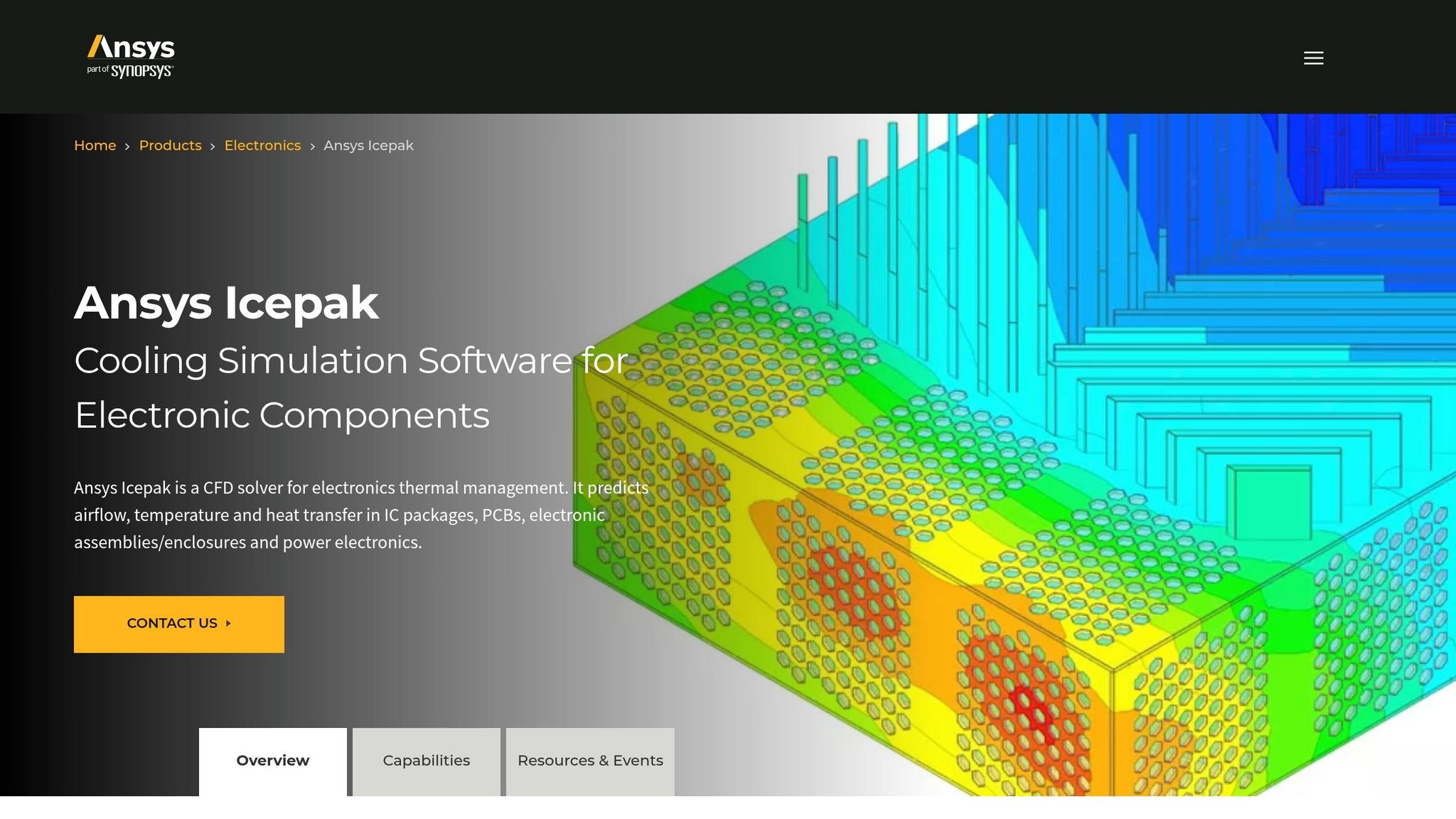
Ansys Icepak leverages CFD-based thermal analysis to evaluate airflow and heat dissipation within high-voltage enclosures. It excels at modeling thermal behavior in power modules, busbars, and enclosures.
A standout feature of Icepak is its integrated electrothermal workflows. Engineers can input electrical loss data directly, enabling precise heat distribution mapping in complex assemblies.
Simulia CST Studio Suite for Electrothermal Analysis

CST Studio Suite starts by analyzing electric field and current distribution, translating this data into thermal loads. This makes it particularly effective for components like insulators, bushings, and busbars, where electromagnetic energy conversion to heat is critical.
The tool considers both resistive (Joule) heating and dielectric losses caused by high electric fields, ensuring accurate representation of localized heating in insulating materials.
PLECS for System-Level Thermal Design
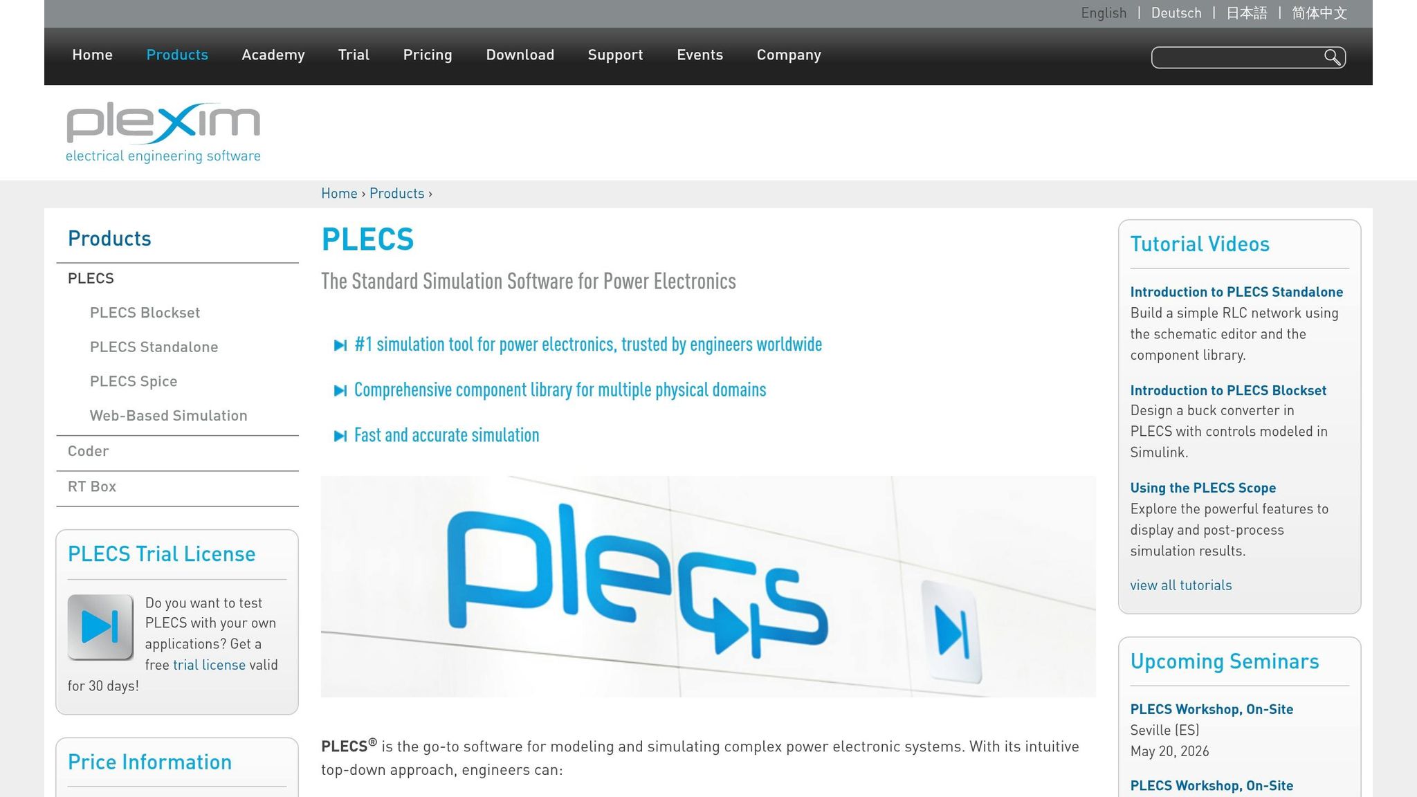
Developed by Plexim, PLECS focuses on system-level simulations. It uses ideal switch models and 3D look-up tables to calculate switching and conduction losses based on forward current, blocking voltage, and junction temperature. This method balances simulation speed with accurate loss estimation.
"This combination of ideal switch models with detailed loss data provides an efficient and accurate alternative to detailed device simulations." - Plexim
PLECS also features a "Heat Sink" concept, which models an isothermal enclosure to absorb thermal losses. Engineers can create thermal equivalent networks using lumped resistances and capacitances, offering control over model complexity. Additionally, many power semiconductor manufacturers provide ready-to-use thermal models, simplifying setup.
Ansys Mechanical for Structural and Thermal Analysis
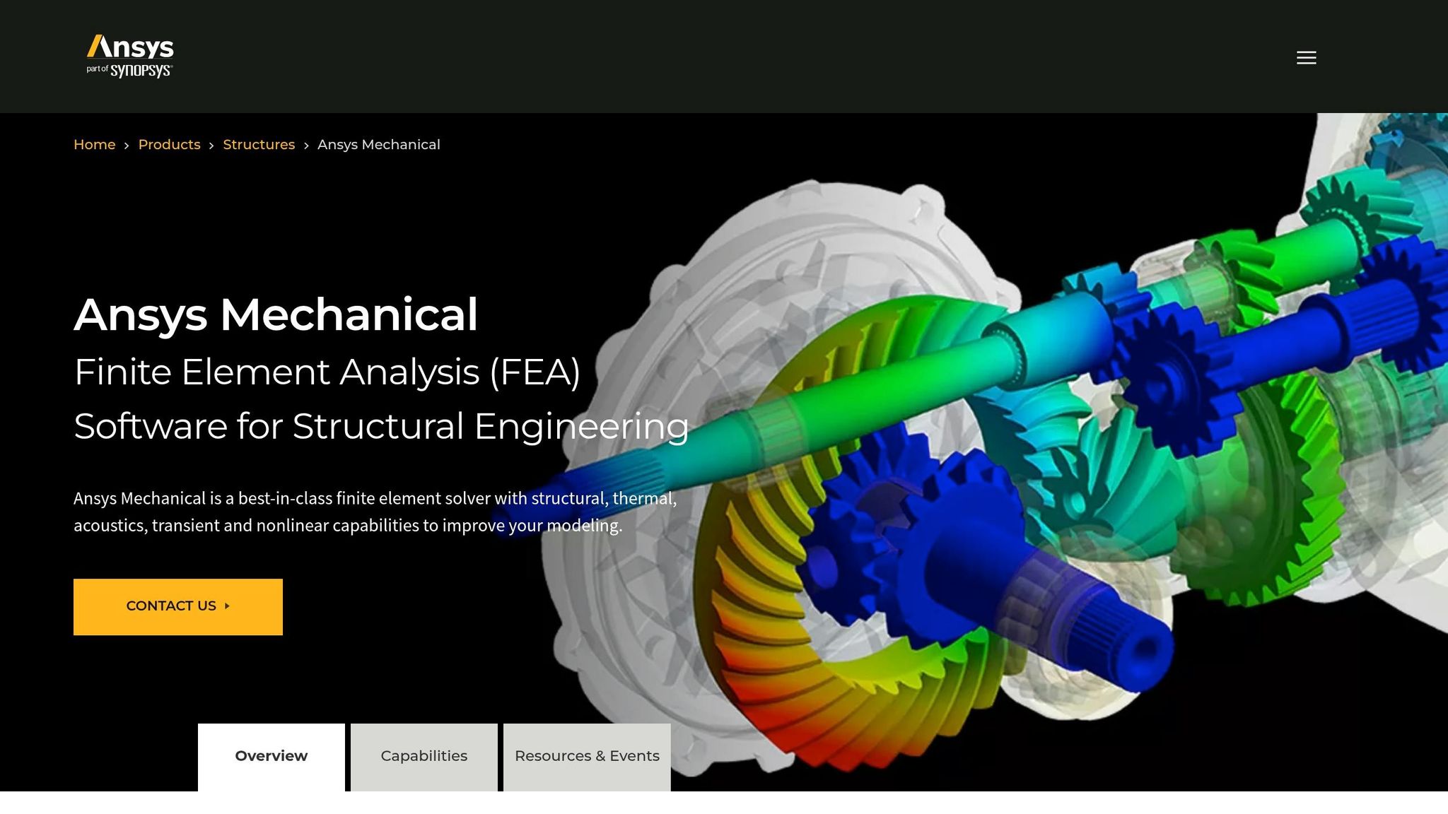
Ansys Mechanical employs FEA to simulate both thermal and structural behaviors. For high-voltage equipment, it can analyze heat distribution in transformer cores and windings while also evaluating mechanical stresses from thermal expansion. This dual capability is invaluable for components like gas-insulated switchgear (GIS) enclosures, where thermal effects and structural integrity are equally critical.
Other Tools Worth Considering
- COMSOL Multiphysics: Offers modular, physics-agnostic modeling, combining electromagnetic, thermal, and fluid modules in one environment. Ideal for unconventional or custom high-voltage setups.
- Siemens Simcenter: Designed for multiphysics scenarios, it integrates seamlessly with Siemens' CAD and PLM systems, making it a strong choice for users already in this ecosystem.
| Tool | Primary Strength | Best Fit |
|---|---|---|
| Ansys Icepak | CFD-based enclosure and busbar analysis | Power modules, full system enclosures |
| CST Studio Suite | Electrothermal load conversion | Insulators, bushings, busbars |
| PLECS | Fast system-level loss and thermal modeling | High-voltage converters, semiconductors |
| Ansys Mechanical | FEA for thermal-structural coupling | Transformers, GIS enclosures |
| COMSOL Multiphysics | Flexible multiphysics modeling | Custom configurations |
| Siemens Simcenter | Integrated Siemens ecosystem workflows | Siemens CAD/PLM users |
Each of these tools brings unique strengths to the table, giving engineers the flexibility to address specific high-voltage challenges with confidence.
A Step-by-Step Workflow for Thermal Analysis of High-Voltage Equipment
Step-by-Step Thermal Simulation Workflow for High-Voltage Equipment
This workflow provides a clear process for performing thermal analysis on high-voltage equipment, building on earlier discussions about simulation tools and their capabilities.
Preparing Data and Models
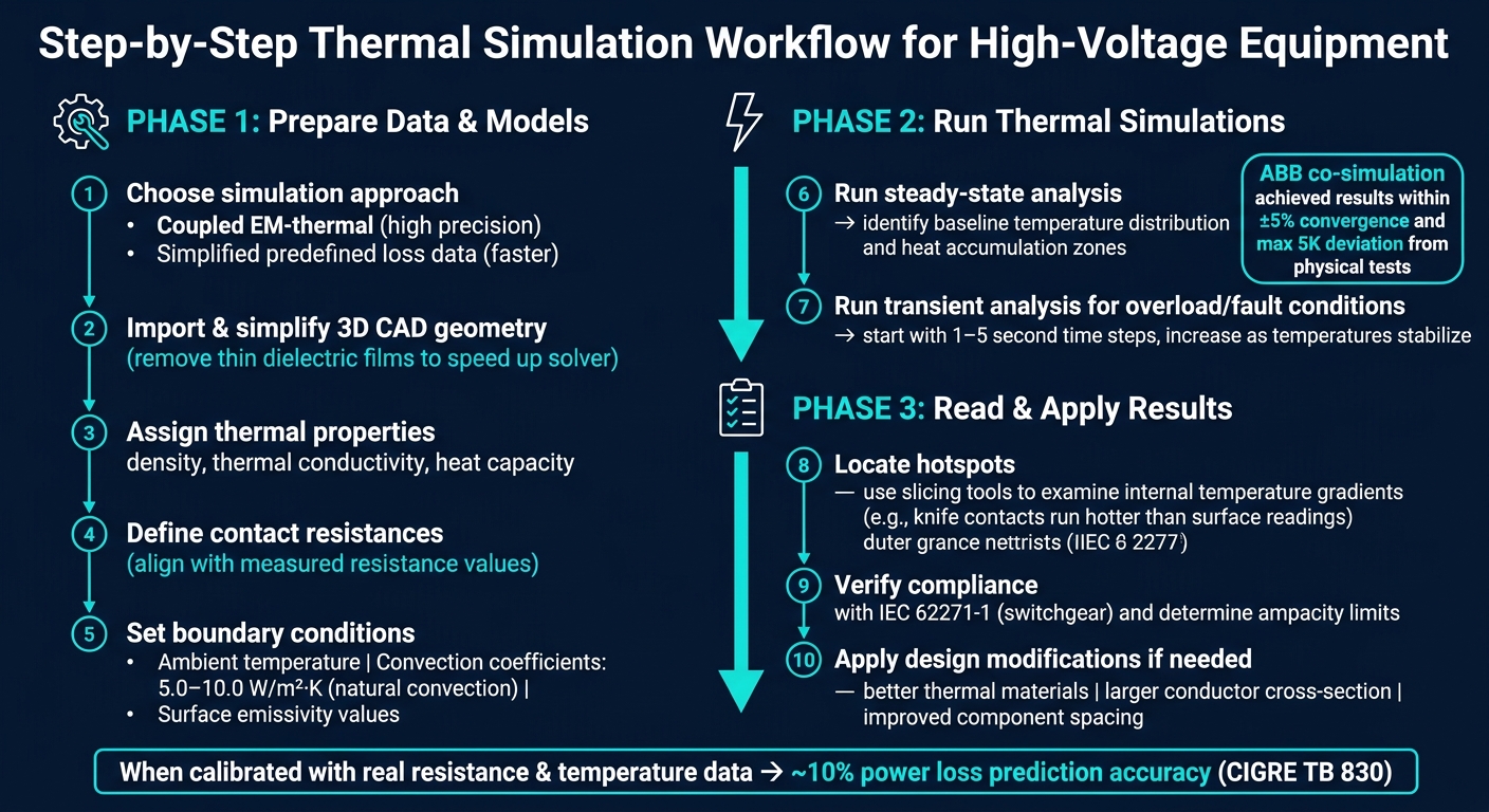
Start by deciding whether to use a coupled electromagnetic-thermal simulation for greater precision or a simplified method with predefined loss data for faster results. The latter is often sufficient for many practical applications.
Next, import your 3D CAD geometry. Simplify the model by removing unnecessary details, such as thin dielectric films, to speed up the solver. Assign thermal properties to each component, including density, thermal conductivity, and heat capacity.
Pay close attention to defining contact resistances. Adjust these to align with measured overall resistance values. Finally, set boundary conditions like ambient temperature, convection coefficients (commonly 5.0–10.0 W/m²·K for natural convection), and surface emissivity values.
Once the model and input parameters are in place, you’re ready to simulate the system’s thermal behavior.
Running Thermal Simulations
Begin with a steady-state analysis to understand the baseline temperature distribution and pinpoint areas where heat accumulates.
For scenarios involving overload or fault conditions, perform a transient analysis. Start with small time steps (1–5 seconds) and gradually increase the step size as temperatures stabilize. A notable example of this method comes from ABB Corporate Research, which used a 3D electrothermal Maxwell-CFD co-simulation to analyze an arc-resistant outdoor medium-voltage circuit breaker. They iteratively exchanged solver data until temperatures stabilized within ±5%, achieving results that closely matched physical tests with a maximum deviation of just 5 K.
After completing the simulation, review the results to identify necessary design improvements.
Reading and Using Simulation Results
The first priority is to locate hotspots. Internal components, such as knife contacts, often reach higher temperatures than surface readings suggest. Use slicing tools to examine internal temperature gradients and compare simulated losses with your predefined heat sources to ensure the model behaves as expected.
This data is invaluable for verifying compliance with standards like IEC 62271-1 for switchgear or determining ampacity - the maximum current a conductor can handle before reaching its thermal limit. As highlighted in CIGRE Technical Brochure 830:
"The performance prediction of a temperature rise simulation can be done when the simulation model is calibrated with previous resistance and temperature measurements."
If any component operates at excessive temperatures, the thermal data can guide design modifications. Options include switching to materials with better thermal performance, increasing the conductor’s cross-sectional area, or improving spacing to reduce the risk of arcing.
Conclusion and Key Takeaways
Thermal simulation tools have become a game-changer for professionals dealing with high-voltage equipment. They replace guesswork with measurable, objective insights, helping identify hotspots at busbar junctions, ensuring compliance with standards like IEC 62271-1 and IEEE Std. 80, and predicting equipment behavior under stress - all before physical testing even begins.
When aligned with real resistance and temperature data, these simulations can achieve power loss predictions with about 10% accuracy. ABB's electrothermal co-simulation studies confirmed this level of precision, showing results that closely matched physical tests.
"Computerized virtual temperature-rise tests enable very fast and relatively inexpensive validation of different breaker designs under a variety of loads and environmental conditions." - ABB Review
This accuracy translates into real-world benefits for everyone involved. Buyers and sellers on platforms like Electrical Trader can leverage these tools in meaningful ways. Buyers can request custom simulation reports that factor in their specific conditions - like soil resistivity, ambient temperature, or fault current levels - to ensure equipment meets their needs. Sellers, on the other hand, can use simulation data to provide clear, verifiable performance evidence, building trust and simplifying transactions.
FAQs
How do I calibrate a thermal model for accurate hotspot temps?
To fine-tune a thermal model for precise hotspot temperature predictions, leverage existing resistance and temperature data to refine input parameters. Pay particular attention to contact resistances and other uncertain factors, adjusting them to match observed resistance values. Achieving accurate predictions depends heavily on choosing the right input parameters and making appropriate simplifications, rather than relying entirely on the simulation tool. Iterative refinements are key to producing dependable outcomes.
When should I run steady-state vs transient thermal simulations?
Steady-state thermal simulations are ideal for assessing the long-term temperature distribution when a system operates under consistent conditions. On the other hand, if you're looking to understand how temperatures fluctuate over time - like during load shifts, startup, or shutdown - transient thermal simulations are the better choice. Each approach serves a distinct purpose depending on whether you're focusing on stability or dynamic changes.
What inputs most affect temperature-rise results in HV equipment?
The main factors influencing temperature-rise outcomes in high-voltage equipment are power losses - which include resistive and contact resistances - and heat dissipation mechanisms like radiation, convection, and conduction. These elements are critical in assessing thermal performance and should be thoroughly accounted for during simulations.