How to Prevent CTE Mismatch Failures
CTE mismatch occurs when materials expand or contract at different rates due to temperature changes, causing stress and potential failures in bonds or components. This is especially problematic in electronics, medical devices, and industrial equipment, where repeated thermal cycling can lead to solder joint fatigue, cracks, or delamination.
To minimize these issues:
- Match materials with similar CTE values: Use materials with closer thermal expansion rates to reduce stress.
- Use flexible adhesives: Low-modulus adhesives or buffer layers can absorb stress between mismatched materials.
- Test and simulate: Perform thermal cycling tests and use Finite Element Analysis (FEA) to predict and mitigate stress points.
- Select high-performance components: Choose materials with appropriate glass transition temperatures (Tg) and thermal properties for your application.
4135b Semiconductor Packaging -- Mechanical -- CTE mismatch
sbb-itb-501186b
Selecting Materials to Minimize CTE Mismatch
Common Materials CTE Values and Compatibility Chart
Understanding Material Properties
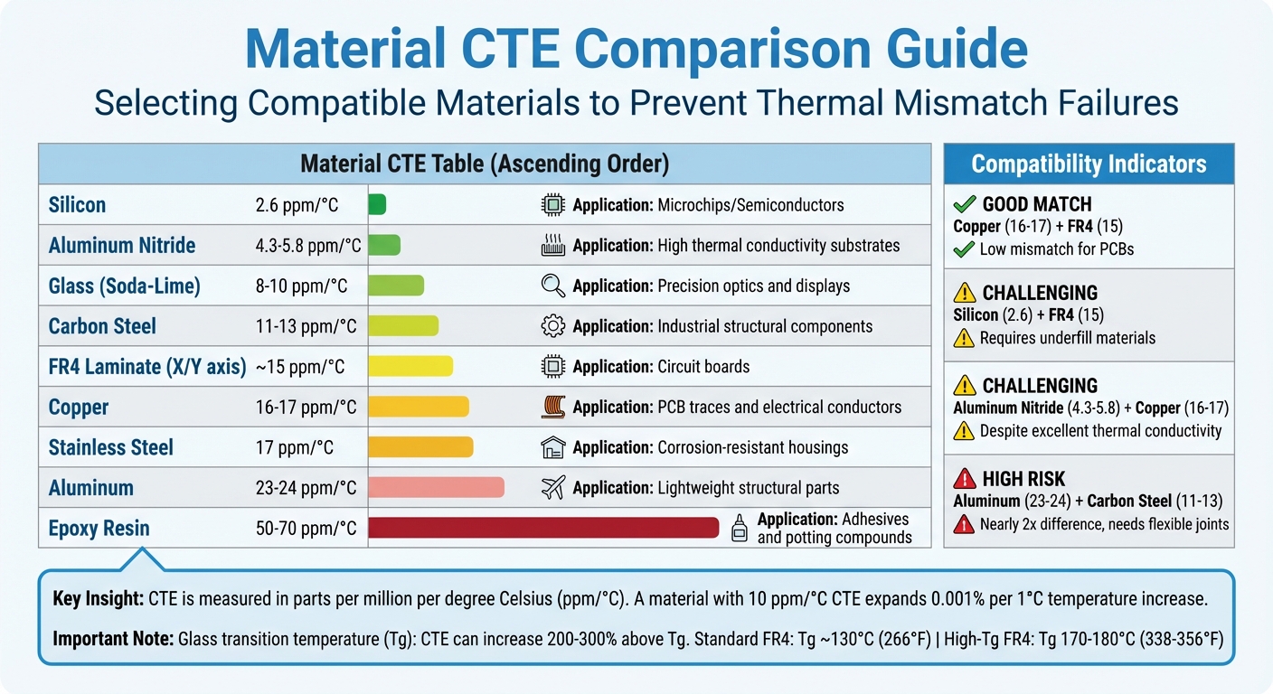
Choosing materials that work well together starts with understanding how they expand and contract with temperature changes. CTE (Coefficient of Thermal Expansion) is measured in parts per million per degree Celsius (ppm/°C). For example, a material with a 10 ppm/°C CTE will expand by 0.001% of its length for every 1°C increase in temperature.
CTE can be measured in two ways: linear CTE, which tracks changes in length, and volumetric CTE, which measures changes in volume. For materials that expand evenly in all directions (isotropic materials), the volumetric CTE is about three times the linear CTE. Another key factor to consider is the glass transition temperature (Tg). Once a material exceeds its Tg, its CTE can increase by 200% to 300%. For example, standard FR4 laminates typically have a Tg around 130°C, while high-Tg versions can handle 170–180°C.
Some materials expand differently in different directions, a property known as anisotropy. This behavior becomes important when designing components like through-holes or vias, as uneven expansion can cause stress.
The goal is to select materials with similar CTE values to avoid thermal mismatch failures. Understanding these properties helps in making better choices for combining materials.
Matching Materials for Critical Components
When designing assemblies, it's crucial to pair materials with closely aligned CTE values. A smaller CTE difference (Δα) reduces stress on bonds, especially over a wide temperature range (ΔT). The stiffness of the bonding material (E) also plays a role in determining how much stress builds up. Even small mismatches can lead to damage over time due to repeated thermal cycling.
"Matching the CTE as closely as possible to that of the substrate to be potted is crucial in potting electronic circuits." - Paula Bermudez, Crosslink Technology
For printed circuit boards (PCBs), copper (16–17 ppm/°C) pairs well with FR4 (around 15 ppm/°C), resulting in a relatively low mismatch. However, silicon chips (2.6 ppm/°C) bonded to FR4 boards pose a bigger challenge. In such cases, specialized underfill materials are needed to prevent failures. When mismatched materials can't be avoided, you can use flexible, low-modulus adhesives to absorb stress. Another solution is adding a buffer layer, an intermediate material with a CTE between the two substrates, to reduce stress.
Examples of Compatible Material Combinations
Here’s a quick reference table showing common material pairings and their CTE values:
| Material | Linear CTE (ppm/°C) | Typical Application |
|---|---|---|
| Silicon | 2.6 | Microchips/Semiconductors |
| Aluminum Nitride | 4.3 - 5.8 | High thermal conductivity substrates |
| Glass (Soda-Lime) | 8 - 10 | Precision optics and displays |
| Carbon Steel | 11 - 13 | Industrial structural components |
| FR4 Laminate (X/Y axis) | ~15 | Circuit boards |
| Copper | 16 - 17 | PCB traces and electrical conductors |
| Stainless Steel | 17 | Corrosion-resistant housings |
| Aluminum | 23 - 24 | Lightweight structural parts |
| Epoxy Resin | 50 - 70 | Adhesives and potting compounds |
Some material pairings, like aluminum and carbon steel, highlight the challenges of mismatched CTEs. Aluminum’s CTE (23–24 ppm/°C) is nearly double that of carbon steel (11–13 ppm/°C), which can lead to thermal fatigue unless flexible joints or interlayers are used. Similarly, aluminum nitride and copper are difficult to pair due to their differing CTEs (4.3–5.8 ppm/°C vs. 16–17 ppm/°C), despite aluminum nitride’s excellent thermal conductivity.
For adhesives and potting materials like epoxy resins, you can adjust the CTE by incorporating specific fillers. This approach allows you to better match the CTE of your substrate, making otherwise incompatible materials work together.
These examples demonstrate how thoughtful material selection can minimize thermal stress and improve the reliability of your designs.
Design Strategies to Prevent CTE Mismatch Failures
Using Flexible Joints and Compliant Structures
When joining materials with different rates of thermal expansion, flexible joints can help by absorbing thermal stress instead of letting it concentrate at the bond line. One way to achieve this is by using adhesives with a low Young's Modulus, which allows them to stretch and compress under stress.
Increasing the thickness of the adhesive bond line is another way to distribute stress caused by differential expansion. Some high-performance adhesives can stretch up to 100%–300% before breaking, making them well-suited for managing large thermal expansion differences.
Another technique involves applying extra adhesive at joint edges or encapsulating the entire assembly. This adds surface area to resist peel forces caused by expansion differences. For electronics manufacturing, UV-curing systems are particularly useful, as they allow localized bonding without heating the entire assembly - a critical feature when working with heat-sensitive components.
These flexible joint designs can be further enhanced with tailored fillers and adhesives to better manage temperature-induced stress.
Incorporating Fillers and Adhesives
Adhesive formulations play a key role in reducing thermal mismatch issues. Adding inorganic fillers, such as silica, to adhesives can adjust their coefficient of thermal expansion (CTE) to align more closely with that of rigid substrates. These formulations typically aim for a CTE range between 20 µm/m°C and 50 µm/m°C. Additionally, low-shrinkage adhesives - those that shrink less than 1% during curing - help minimize stress introduced during the bonding process.
For thermal-cure adhesives, curing at a temperature that falls midway between the assembly's expected high and low service temperatures can reduce the overall stress range the joint will experience.
In addition to adhesive selection, pre-stress techniques can provide another layer of protection against thermal stress.
Applying Pre-Stress Compensation Techniques
Pre-stress compensation methods address thermal expansion issues before they cause damage. For example, in printed circuit boards, thicker copper plating on high aspect-ratio vias can reduce stress concentrations along via walls, preventing fractures during thermal cycling. This is especially important because FR4 laminates typically have a CTE of about 15 ppm/°C in the X/Y axes but a much higher 70 ppm/°C in the Z-axis.
Dual-cure adhesive systems offer another effective solution. Hybrids like UV/silicone or UV/urethane provide an initial "tack" cure to secure components quickly, followed by a secondary cure for long-term flexibility.
Testing and Simulation for CTE Reliability
After selecting materials and refining designs, thorough testing and simulation are crucial to ensure the reliability of the coefficient of thermal expansion (CTE) in real-world conditions.
Conducting Thermal Cycling Tests
Thermal cycling tests repeatedly expose components to alternating high and low temperatures, mimicking the expansion and contraction cycles they experience over time. These tests are particularly useful for replicating thermal stresses encountered during processes like reflow soldering. During testing, focus on high-risk areas such as via necks, layer interfaces within stacked or buried vias, and the corners of BGA packages, as these zones often bear the brunt of differential expansion stress.
Before testing, always consult material datasheets for CTE and glass transition temperature (Tg) details, especially for boards designed for extreme environments. For instance, standard FR4-grade laminates typically have a Tg around 266°F, while high-Tg laminates can reach 338–356°F. When configuring reflow soldering profiles, ensure settings minimize BGA corner expansion and prevent solder bridging.
The data from these tests lays the groundwork for predictive modeling through simulation tools.
Using Finite Element Analysis (FEA) Tools
Once physical testing is complete, simulations offer an efficient way to refine designs further. FEA software can model thermal stresses before creating physical prototypes. Start by building 2D or 3D models that include all critical components, such as cores, windings, insulating layers, and external housings. Run initial electromagnetic simulations to estimate internal heat sources like copper losses.
Set up thermal boundaries to capture both internal and external heat transfer. Define the worst-case temperature conditions your product might encounter during operation or storage. The software can then solve coupled heat transfer equations to predict temperature distributions and pinpoint hot spots where stress is likely to build up. For more complex assemblies, you might use a conjugate heat transfer approach, which accounts for both conduction in solids and convection in fluids. Always cross-check simulation outcomes with experimental data and manufacturer test reports to ensure accuracy.
These simulations help identify areas for design adjustments to lower thermal stress.
Interpreting Test Results for Practical Improvements
When reviewing test data, focus on regions prone to stress, such as via necks and layer interfaces. Compare these findings with earlier design adjustments to determine their effectiveness in improving reliability. Pay close attention to whether failures occurred near or above the material's Tg, as CTE values can change significantly beyond this point. For instance, fractures in high aspect-ratio vias may indicate the need for thicker copper plating to distribute stress more evenly.
If delamination occurs, reducing copper layer thickness could help, as thicker copper tends to generate more stress during temperature changes. Warpage issues in wafers or boards might be mitigated by adjusting thermal profiles to allow for gradual heating, enabling materials to reach thermal equilibrium and minimizing mechanical strain.
Also, consider the geometry of components - high aspect-ratio vias with thin copper plating are more prone to cracking. The resin content in laminates is another factor to account for, as higher resin levels can increase CTE mismatch relative to copper. When analyzing solder joint failures, remember that both CTE mismatch and vibration can contribute to mechanical fatigue.
Sourcing Reliable Components from Electrical Trader

Why Choose Electrical Trader?
Once you've identified the risks of CTE mismatch through testing and simulations, the next step is finding components that can handle thermal stress effectively. Electrical Trader offers electrical components that meet UL, IEC, and CSA standards, ensuring they can endure extensive temperature cycles. For instance, their high-Tg laminates maintain structural integrity at temperatures as high as 356°F (180°C), compared to standard FR4 laminates, which typically max out at 266°F (130°C). These high-performance materials are part of a broader range of products designed to address CTE mismatch challenges.
Key Products to Address CTE Mismatch
Electrical Trader's inventory includes a variety of certified products tailored to manage thermal expansion and prevent failures. These include:
- Current transformers and split-core transformers: Ideal for retrofitting existing systems with minimal downtime.
- MCCs and VFDs: Built to endure repeated thermal cycling, reducing risks like material creep and insulation failure.
- Adhesives and silicones: UV-curable epoxies and thermally conductive silicones provide shock absorption between dissimilar materials, ensuring precise CTE matching.
- Ceramic substrates: Options like Alumina and Low Temperature Co-fired Ceramics (LTCC) closely match the thermal expansion rates of silicon components, minimizing warpage during assembly.
These products are carefully designed to combat the challenges posed by thermal stress, helping professionals maintain system reliability.
Simplified Procurement for Professionals
Electrical Trader doesn't just offer quality components - it also streamlines the purchasing process. Their platform organizes products like breakers, transformers, voltage equipment, and power generation tools into easy-to-navigate categories, saving time for professionals searching for components with specific thermal properties.
Additionally, their resource center provides buying guides to help users confirm compliance with standards like IEC 61869-2 or IEEE C57.13 before making a purchase. Feedback from customers underscores the importance of sourcing from a reliable marketplace, as poor-quality components often fail within six months due to issues like inadequate potting compounds. Electrical Trader mitigates these risks by partnering with verified suppliers. For bulk orders, they even facilitate sample testing and warranty verification, with many suppliers offering warranties of at least two years.
Conclusion and Key Takeaways
Summary of Prevention Strategies
Avoiding CTE mismatch failures requires a thorough, proactive approach that begins at the design stage. The first step is choosing materials with closely matched CTE values. When that's not feasible, buffer layers with intermediate expansion rates can help bridge the gap between substrates. Flexible adhesives like silicones or urethanes are excellent options - they act as shock absorbers, offering elasticity to reduce stress. Additionally, design techniques such as expansion joints, compliant structures, and maintaining consistent bond line thickness (using spacers like glass beads) allow for controlled movement and minimize the risk of fractures.
Testing is equally critical. Thermal cycling tests and finite element analysis (FEA) can simulate extreme conditions to ensure your design holds up. Always calculate for worst-case scenarios, considering the full temperature range your equipment will encounter. Keep in mind that shear stress at the bond line increases with larger CTE differences, greater temperature swings, and stiffer adhesives.
These strategies work together to create a design that can handle thermal stress effectively.
Final Thoughts on Ensuring Reliability
By combining thoughtful material choices, smart design, and rigorous testing, you can significantly reduce the risk of CTE mismatch failures. This is especially important for components exposed to repeated thermal cycling. Over time, thermal cycling can cause stress accumulation, leading to fatigue failures - even when stresses stay below the material's yield strength. The results can be severe: delamination, cracking, loss of hermeticity, and in electrical systems, solder joint fatigue that disrupts continuity after thousands of cycles.
The good news? These issues are avoidable with careful planning and sourcing. As we've discussed, starting with proper material selection and sourcing certified components is key. Electrical Trader simplifies this process by offering components specifically designed to handle thermal cycling. From transformers that endure extreme conditions to adhesives and ceramic substrates with precise CTE matching, their inventory supports thermomechanical reliability. Their resource center also provides tools to verify compliance with industry standards, ensuring you make informed choices. By pairing smart design with reliable materials, you can extend the lifespan and reliability of your equipment under demanding conditions.
FAQs
What CTE difference is “too much” for my temperature range?
When the difference in Coefficient of Thermal Expansion (CTE) between bonded materials becomes large enough to cause significant stress, it’s considered "too much." This often happens when the mismatch exceeds 10-20 ppm/°C, especially during wide temperature fluctuations. To avoid such failures, it’s important to:
- Use flexible adhesives with a low Young’s Modulus.
- Design joints that can accommodate differential expansion while keeping stress levels low.
These strategies can help maintain the integrity of the bond and reduce the risk of temperature-related damage.
How do I choose an adhesive that won’t crack under thermal cycling?
When selecting an adhesive, focus on high flexibility and a low modulus to accommodate stresses caused by thermal expansion differences. Opt for adhesives with a low Young’s Modulus and high elongation capability, allowing them to stretch and compress alongside materials during temperature fluctuations. To further improve durability under thermal cycling, consider designing joints with fillets or encapsulation, which help distribute stress more evenly.
What tests should I run to prove my design is CTE-safe?
To make sure your design is safe for current transformer equipment (CTE), it's crucial to perform thorough testing. Start with pre-commissioning checks for high-voltage current transformers (CTs) and follow detailed commissioning procedures.
Key steps include:
- Verifying the integrity of the CT to ensure it's in good condition.
- Checking insulation to confirm it's properly installed and functioning.
- Testing the system's operation under load to ensure everything works as expected.
You can also carry out primary injection testing, which evaluates the protection system's wiring and functionality. This method allows you to test without disturbing existing connections, helping to prevent mismatch failures and ensuring the system operates correctly.