Thermal Cycling Effects on Breakers and Transformers
Thermal cycling, or the repeated heating and cooling of electrical components like breakers and transformers, accelerates wear and reduces lifespan. This process is influenced by load changes, ambient temperature, and the growing variability from renewable energy sources. Key takeaways include:
- Transformers: Thermal cycling speeds up insulation degradation, particularly in the insulating paper, which weakens over time. Hot spots and moisture migration into transformer oil further increase failure risks.
- Breakers: Repeated thermal expansion and contraction cause misalignment, contact erosion, and insulation damage, leading to operational failures like current chopping and voltage transients.
To mitigate these effects, real-time monitoring tools, dynamic thermal ratings, and precise load management are critical. These strategies help extend the life of vital equipment and improve reliability in an increasingly unpredictable energy grid.
High-Temperature Reliability: Thermal Cycling Test
sbb-itb-501186b
How Thermal Cycling Works in Transformers
Transformers undergo physical changes as they heat up and cool down, a process driven by load variations. When the load increases, heat causes components to expand; when it decreases, cooling leads to contraction. Because different materials expand at different rates, internal friction and stress points develop over time. J.W.B. Kers from Delft University of Technology highlights the challenges of modern grids:
The grid of the future will still be partly composed of today's components... current components, like paper-oil transformers, will be further stressed.
In October 2023, researchers observed that reclosing currents caused mechanical stress as high as 8.71 MPa and temperatures reaching 113.7°C (about 237°F) on insulating paper. Their findings revealed that combined electrical, thermal, and mechanical aging accelerated the degradation of the paper’s polymerization degree and tensile strength more severely than aging caused by any single factor. These thermal stresses directly impact the internal components of transformers.
Effects on Windings and Insulation
Thermal cycling poses two primary risks to windings: mechanical deformation and insulation failure. Copper windings expand and contract repeatedly, gradually weakening the clamping forces that secure them. This makes the windings more susceptible to displacement during short-circuit events.
The insulating paper also suffers under thermal cycling. When its degree of polymerization (DP) drops below 200, the paper becomes brittle and prone to flaking during normal vibrations. Research confirms:
Mechanical–thermal coupled aging has a more significant effect on the degradation of insulating paper mechanical properties compared to thermal aging.
Temperature fluctuations also create hot spots - localized areas where heat accumulates. These hot spots age faster than other parts of the insulation, forming weak points that can fail without warning. A reduction of 50% to 75% in tensile strength is often used to determine the technical end-of-life for transformers. Recognizing how these materials respond to thermal stress is essential for evaluating transformer durability. Beyond windings and insulation, thermal cycling also impacts transformer oil and seals.
Effects on Transformer Oil and Seals
Transformer oil faces unique challenges during thermal cycling. Sudden temperature increases cause moisture to move from the paper insulation into the oil, a phenomenon known as osmotic behavior. This process is closely tied to loading conditions and can happen rapidly during overloading. If moisture levels in the insulation exceed 3% to 4%, rapid heating can generate bubbles in the oil. As IEEE researchers explain:
The evidence of bubbles in the liquid weakens the dielectric integrity of the insulation system.
These bubbles compromise the oil’s ability to insulate and cool, creating an immediate risk of failure.
Seals and gaskets also endure stress from the repeated expansion and contraction of the transformer tank and internal components. Over time, this leads to dimensional changes - swelling and shrinking - that can cause leaks. Once seals fail, water can enter the system, further increasing moisture levels and accelerating degradation. A survey found that over 93% of utilities rely on oil sample tests to guide transformer end-of-life decisions, with Dissolved Gas Analysis (DGA) being the most widely used diagnostic tool by 95% of utilities.
How Thermal Cycling Affects Breaker Performance
When it comes to circuit breakers, thermal cycling is a silent but persistent adversary. Unlike transformers, which struggle with insulation and oil degradation, breakers are more prone to misalignments and wear caused by repeated heating and cooling. This process, known as thermal cycling, can lead to fatigue that gradually degrades critical components. Researchers at Oak Ridge National Laboratory explain:
The main failures in high power semiconductors are caused by thermomechanical fatigue.
This fatigue disrupts the alignment of breaker contacts, reducing their ability to interrupt current reliably. As components heat up during operation and cool down during idle periods, their differing rates of thermal expansion create misalignment and physical strain. Over time, this compromises the breaker’s functionality and safety.
The consequences of this degradation can be severe. According to IEEE research, thermal and mechanical fatigue often result in abnormal breaker behavior, such as current chopping during opening or prestrike and reignition during closing. These issues generate high-frequency voltage transients - ranging from 1 kHz to 10 kHz - that can damage connected equipment. David D. Shipp highlights the risks:
The voltage-transient severity is exacerbated when the circuit breaker operates abnormally, i.e., current chopping upon opening and prestrike or reignition voltage escalation upon closing.
Let’s take a closer look at how thermal cycling impacts two critical areas: contact surfaces and insulation integrity.
Wear on Contacts and Arc Chutes
Thermal cycling places immense stress on breaker contact surfaces, directly affecting their performance and longevity. With each cycle of heating and cooling, metal contacts expand and contract, leading to misalignment. This misalignment increases resistance, creating localized hot spots that accelerate wear and tear.
Arc chutes, which are responsible for extinguishing electrical arcs during switching, also face significant challenges. These components are made from materials with varying coefficients of thermal expansion (CTE), meaning they expand at different rates when exposed to heat. This mismatch in expansion creates internal strain, leading to warping and, eventually, structural damage. Vacuum and SF6 breakers are particularly susceptible, especially in demanding applications like Electric Arc Furnaces and Ladle Melt Furnaces, where inductive loads cause extreme switching stress.
Insulation Degradation and Failure Risks
Breaker insulation doesn’t escape the effects of thermal cycling either. The constant expansion and contraction cause insulation to crack, delaminate, and form voids. These defects allow moisture and contaminants to infiltrate, accelerating chemical erosion and reducing the insulation’s dielectric strength.
Studies on impregnated insulation reveal a troubling trend: while breakdown voltage initially increases with moderate temperature rises, it begins to drop by 23.5V/°F once temperatures exceed 140°F (60°C). Transient voltage spikes further worsen the situation, increasing the tangent delta - a measure of insulation loss - by 6.4% compared to standard AC waveforms. The risks are stark: 31% of electrical fires are traced back to the ignition of wire or cable insulation, and between 2014 and 2016, 11% of U.S. electrical fires were directly linked to short-circuit arcs caused by degraded insulation.
Thermal stress also encourages electrical treeing, where microscopic, branch-like discharge channels form within the insulation. With each thermal cycle, these channels grow, gradually eroding the insulation until it fails completely. Systems with short cable connections - less than 200 feet - between breakers and transformers are especially vulnerable, as voltage transients are more pronounced in these setups.
Research Findings on Thermal Cycling Impacts
Studies highlight how thermal cycling accelerates equipment aging by combining temperature stress with mechanical fatigue. These findings emphasize the importance of managing thermal conditions effectively to extend the lifespan of critical equipment.
Transformer Lifespan and Temperature Stress
When transformer insulation experiences a 10°F (5.6°C) temperature rise, its lifespan is cut in half. This principle, supported by laboratory tests on cellulose-based paper insulation, has become a standard in the industry.
In October 2023, a team from the Electric Power Research Institute of State Grid Beijing Electric Power Co. and North China Electric Power University conducted tests on a SFSZ7-31500/110 transformer model. They simulated a three-phase short-circuit fault lasting 0.1 seconds, followed by circuit breaker reclosing at 0.6 seconds. During these tests, insulating paper was subjected to mechanical stress of 8.71 MPa and temperatures reaching 113.7°C. Researchers found that the combination of mechanical and thermal stress caused faster degradation compared to thermal stress alone. Zonghui Yuan, one of the researchers, observed:
"The insulating paper's resistance to mechanical damage, specifically short-circuit resistance, noticeably decreased after extended thermal cycling."
The end-of-life for transformer insulation typically occurs when the Degree of Polymerization (DP) drops from 1,000–1,200 to 200–300 or when its tensile strength falls below 50% of the original value. To monitor this degradation, over 93% of utilities now use oil sample tests, such as Dissolved Gas Analysis (DGA) and 2-Furfural (2FAL) measurements, allowing them to assess insulation health without opening the transformer tank.
While transformers face rapid insulation aging, breakers encounter their own unique challenges due to thermal cycling.
Breaker Durability and Temperature Fatigue
Breakers, like transformers, are affected by repeated thermal cycling, but their issues are primarily mechanical. The constant expansion and contraction of materials during these cycles lead to wear and tear, deformation of internal components, and loosening of fasteners. Unlike transformers, where insulation aging is the main concern, breakers suffer from cumulative mechanical fatigue that impacts moving parts and contact surfaces.
Failures in both transformers and breakers rarely stem from a single event. Instead, gradual degradation from repeated thermal cycles and through-faults reduces their operational life. Installing circuit breaker monitors can help mitigate these stresses by limiting exposure to through-faults. This is especially critical for vacuum or SF₆ breakers used in demanding environments with frequent load changes or harsh conditions. Such monitoring systems play a key role in extending the lifespan of these components.
Transformers vs. Breakers: Thermal Cycling Comparison
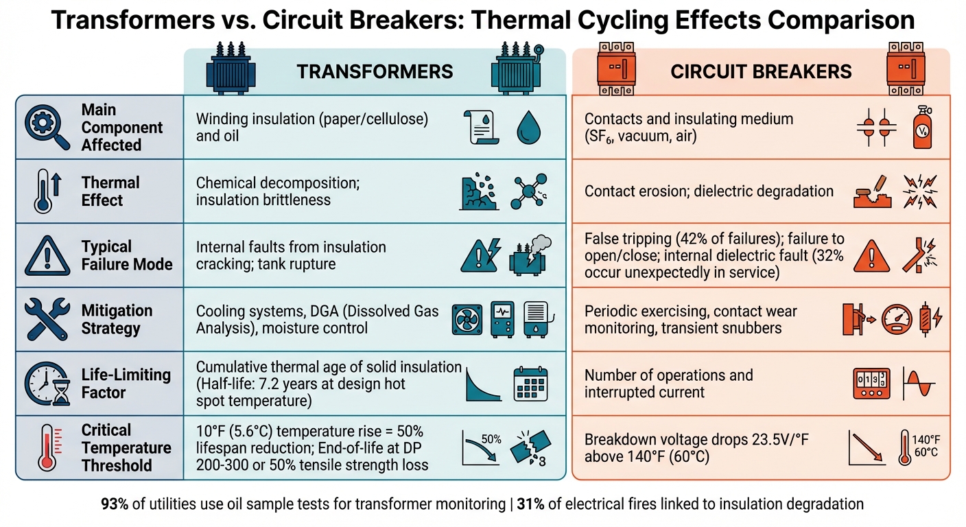
Transformers vs Circuit Breakers: Thermal Cycling Effects Comparison
Transformers and circuit breakers respond differently to thermal cycling, each with unique challenges and failure mechanisms. Transformers primarily suffer from chemical breakdown in their insulation materials, while breakers face mechanical wear and contact erosion. Understanding these distinctions helps clarify what limits their lifespan and how they fail.
For transformers, lifespan is tied to the cumulative thermal aging of their solid insulation. When operated consistently at their design hot spot temperatures (95°C for 55°C rise insulation or 110°C for 65°C rise), the insulation's half-life is about 7.2 years. On the other hand, breakers are constrained by the number of operations they perform and the total interrupted current they handle.
Failure modes further highlight their differences. Transformers are vulnerable to moisture and high temperatures exceeding 140°C, which can generate free bubbles in the oil, leading to sudden internal faults. Breakers, however, have distinct issues: 42% of failures involve false tripping (unintended opening), and 32% occur unexpectedly while in service rather than during switching operations.
Edvard Csanyi from Electrical Engineering Portal offers this insight:
The life of a transformer is often defined as the time required for the mechanical strength of the insulation material to lose 50% of its mechanical strength.
The table below provides a concise comparison of these two components:
Comparison Table: Transformers vs. Breakers
| Feature | Transformers | Circuit Breakers |
|---|---|---|
| Main Component Affected | Winding insulation (paper/cellulose) and oil | Contacts and insulating medium (SF₆, vacuum, air) |
| Thermal Effect | Chemical decomposition; insulation brittleness | Contact erosion; dielectric degradation |
| Typical Failure Mode | Internal faults from insulation cracking; tank rupture | False tripping; failure to open/close; internal dielectric fault |
| Mitigation Strategy | Cooling systems, DGA, moisture control | Periodic exercising, contact wear monitoring, transient snubbers |
| Life-Limiting Factor | Cumulative thermal age of solid insulation | Number of operations and interrupted current |
Monitoring and Mitigation Strategies
Breakers and transformers are particularly susceptible to thermal cycling, making proactive monitoring and mitigation essential for extending their operational lifespan. Keeping a close watch on temperature is a key factor in managing the thermal stresses discussed earlier.
Temperature Monitoring and Control Methods
Dynamic Thermal Rating (DTR) offers a more responsive approach compared to static methods. Instead of relying on fixed temperature limits based on average daily conditions, DTR systems use real-time environmental data to determine permissible load levels. Critical indicators like Hot-Spot Temperature (HST) in windings and Top-Oil Temperature (TOT) in tanks play a central role in these systems, guiding decisions that impact equipment health.
Modern thermal models incorporate factors like rainfall, wind speed, wind direction, and solar radiation to estimate HST. Tools like Winding Temperature Indicators (WTI) are widely used for both historical data analysis and real-time monitoring. These indicators help operators spot irregularities early, reducing the risk of damage.
A long-term study spanning 34 years (1985–2019) highlighted DTR's benefits. By analyzing hourly ambient temperature data and system limits, researchers found that DTR could boost capacity by up to 45% beyond nominal ratings while avoiding accelerated insulation wear. Remarkably, DTR ratings exceeded nominal ratings consistently - 100% of the time.
These monitoring strategies directly support practices like derating and dynamic loading, ensuring equipment operates within safe thermal boundaries.
Derating for Environmental Conditions
Accurate temperature monitoring also enables precise derating, which helps prevent accelerated insulation aging. By adjusting operational limits to match ambient conditions, operators can avoid critical temperature thresholds that would otherwise shorten equipment life. This is especially important in regions with extreme temperatures, like tropical climates, where temperatures often hit 30°C or higher.
The effects of temperature on transformer capacity are quantifiable. For ONAN (Oil Natural Air Natural) cooling systems, transformer loading capacity decreases by 1.06% to 1.2% per degree Celsius between 21°C and 35°C. For ONAF (Oil Natural Air Forced) systems, the decrease is slightly less, at 0.87% to 0.96% per degree. Operating a transformer continuously at its HST limit can accelerate insulation aging significantly - 12.9 times faster for non-thermally upgraded paper and 2.7 times faster for thermally upgraded paper.
The IEC 60076–7:2005 standard emphasizes this balance:
The temperature and current limits are not intended to be valid simultaneously. The current may be limited to a lower value... in order to meet the temperature limitation requirement.
When planning derating strategies, professionals should incorporate at least 30 years of historical temperature data to account for climate variability. This approach requires monitoring multiple parameters - current, HST, and TOT - since the limiting factor can shift depending on environmental conditions. Such derating practices help counteract the insulation degradation and thermal stress issues highlighted earlier.
Dynamic Loading Practices
Effective load management goes beyond standard load profiles to consider real-world factors like distributed energy resources, energy storage, and electric vehicles. The feasible region approach aligns transformer loading with ambient conditions, providing 5% extra capacity in temperate climates and 15% in continental climates. This requires thermal models calibrated with heat run test data, as transformers with identical ratings can behave differently under load.
Monitoring bottom oil temperature at the cooling system outlet offers a more precise measure of cooling efficiency compared to top-oil measurements. For emergency scenarios, operators should pre-calculate loading values for two conditions: maximum cooling capability and zero cooling capability in case of system failure. When implemented correctly, dynamic thermal rating systems deliver higher ratings than static systems 80% to 90% of the time.
Conclusion
Thermal cycling poses a serious risk to breakers and transformers by speeding up the wear and tear of key components - especially insulating paper, which cannot be replaced. As J.W.B. Kers from Delft University of Technology explained:
In a transformer, the insulation is the most critical parameter for it cannot be replaced (e.g. like contaminated oil) and insulation failures are severe in both number and in cost.
A clear understanding of hot-spot temperature (HST) and its role in insulation aging is crucial for managing these assets effectively. The shift toward renewable energy sources adds to the challenge, creating transient spikes and inconsistent power delivery that put additional strain on insulation systems. This becomes even more pronounced in tropical climates, where average ambient temperatures of 86°F (30°C) - compared to the IEC standard of 68°F (20°C) - reduce transformer capacity by about 1.06%–1.2% per °C (0.59%–0.67% per °F) under ONAN conditions.
Atip Doolgindachbaporn from the University of Southampton highlighted the importance of load adjustments in managing transformer longevity:
Transformer life could be shortened or extended by adjusting loads which results in higher or lower temperature conditions.
To address these challenges, strategies like dynamic thermal ratings, real-time monitoring with winding temperature indicators (WTIs), and smart derating can help extend equipment life and maintain performance. Additional measures such as oil treatment, active drying, and component upgrades can delay the need for replacements.
Condition-based maintenance offers a more targeted approach, shifting from routine schedules to data-driven decisions. By monitoring HST and adjusting dynamic loading practices to reflect environmental factors, operators can extend the lifespan of their equipment while avoiding unnecessary replacements. For those seeking replacement components or upgrades, platforms like Electrical Trader provide access to a range of new and used breakers, transformers, and other power distribution equipment.
Proactive thermal cycling management ensures long-term reliability, optimizes return on investment, and supports safe grid operation. With power transformers often expected to last over 40 years, these strategies are essential for protecting both critical infrastructure and financial outcomes.
FAQs
What are the first warning signs of thermal cycling damage?
Thermal cycling damage often starts showing up in subtle ways. You might notice insulation breakdown, which weakens the protective layers. Then, there are micro-cracks, tiny fractures that can lead to partial discharge activity, signaling potential electrical issues. Mechanical stress can also leave its mark, with signs like wear or damage to insulation systems. Over time, these problems can chip away at the durability and efficiency of breakers and transformers, making them less reliable.
How can I reduce thermal cycling without cutting capacity too much?
To keep thermal cycling in check while preserving capacity, it's crucial to handle temperature changes smartly. Start by managing load variations carefully to prevent sudden shifts that can strain equipment and speed up wear and tear. Incorporating dynamic thermal modeling can also make a big difference. This approach helps predict and regulate transformer temperatures, ensuring a more even load distribution.
Another key step is improving cooling systems. Upgrades such as better cooling mechanisms or tweaking oil circulation can help stabilize operating temperatures and minimize the effects of sudden thermal changes.
Which monitors provide the best early detection for breakers vs transformers?
When it comes to monitoring, the best tools depend on the equipment in question. For transformers, methods like dissolved gas analysis (DGA), oil quality checks, and breakdown voltage testing are crucial. These techniques help spot early signs of insulation aging or degradation. For breakers, specialized sensors focus on tracking electrical parameters, contact wear, and thermal stress. Each method is tailored to address the specific failure risks of these devices, making it easier to catch and prevent potential problems early on.