Heat Dissipation Standards for LV Switchgear
Managing heat in low-voltage (LV) switchgear is critical for safety and performance. Excess heat can lower efficiency, reduce current capacity, and even cause equipment failures like arcing or flashovers. Here's a quick breakdown of key points to know:
- Sources of Heat: Electrical losses (Joule effect), eddy currents, and magnetic hysteresis in components like busbars, circuit breakers, and enclosures.
- Heat Impact: Overheating can cause reduced load capacity, damage to components, and safety risks.
- Temperature Limits: Internal cabinet temperature should not exceed 131°F (55°C) for a 95°F (35°C) ambient environment.
- Compliance Standards: IEC 61439 and U.S. guidelines like IEEE C37.24-2017 outline temperature limits, testing methods, and verification procedures.
- Cooling Methods: Passive cooling (natural airflow) works for standard loads, while active cooling (fans, air conditioning) is needed for higher heat loads.
- Design Tips: Use diagonal vent placement, monitor temperatures, and optimize layouts to manage airflow and reduce heat hotspots.
Proper calculations, efficient airflow, and compliant components ensure safe and reliable switchgear operation. Keep reading for detailed insights on standards, cooling methods, and design strategies.
The art of panelbuilding (2): heat dissipation
sbb-itb-501186b
Standards for Heat Dissipation in LV Switchgear
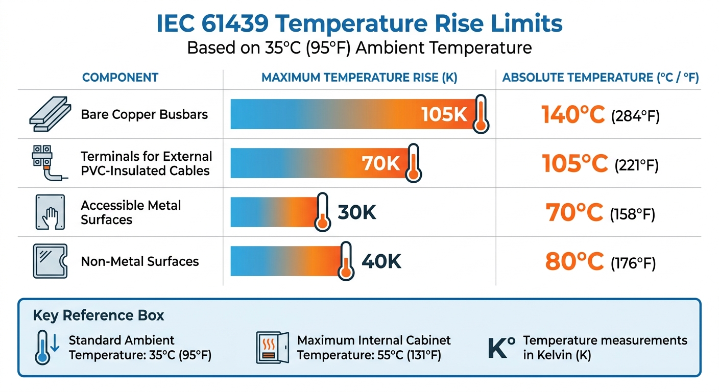
IEC 61439 Temperature Rise Limits for LV Switchgear Components
Ensuring proper heat management in low-voltage (LV) switchgear is critical to avoiding equipment failure and safety risks. Regulatory standards outline temperature limits, testing methods, and verification procedures to keep systems operating safely and efficiently.
IEC 61439 Standards Overview
The IEC 61439 series replaced the older IEC 60439 standard, moving away from TTA/PTTA classifications to a unified Design Verification approach.
Manufacturers can prove compliance with IEC 61439 through one of three methods: physical testing in a lab, calculations using the IEC TR 60890 technical report, or by applying design rules that compare the assembly to a verified reference design. For instance, the 2022 update to IEC TR 60890 extended the calculation scope from 3,150A to 3,200A, which allows for more flexible thermal modeling without needing expensive lab tests. However, for assemblies with multiple compartments, calculation-based verification is typically limited to systems with rated currents up to 1,600A.
The standard also introduced the Rated Diversity Factor (RDF), which accounts for the fact that not all circuits operate at full load simultaneously. RDF values range from 0.4 to 1.0, depending on the number of outgoing circuits. For incoming circuits, an RDF of 0.9–1.0 is recommended, while distribution boards with 10 or more circuits can use an RDF of 0.6–0.7.
Temperature rise limits, measured in Kelvin (K), are a key component of IEC 61439. These limits are based on an ambient temperature of 95°F (35°C). For example:
- Bare copper busbars: maximum temperature rise of 105K
- Terminals for external PVC-insulated cables: maximum rise of 70K
- Accessible metal surfaces: maximum rise of 30K (absolute temperature of 158°F or 70°C)
- Non-metal surfaces: maximum rise of 40K (absolute temperature of 176°F or 80°C)
These standards set the global baseline for compliance, with U.S. guidelines adding further requirements tailored to local conditions.
U.S. Compliance Requirements
While IEC 61439 serves as the international standard, U.S. installations often include additional guidelines. For instance, IEEE C37.24-2017 addresses the impact of solar radiation on outdoor metal-enclosed switchgear, a critical factor in sunny climates where solar heating can significantly increase the thermal load.
In the U.S., compliance heavily emphasizes UL certification and generally prioritizes physical testing over calculation methods. Insulation ratings align closely with IEC standards, such as terminals rated for 158°F (70°C) with PVC insulation or 194°F (90°C) with XLPE insulation. For installations above 6,562 feet (2,000 meters), air clearances must be increased by approximately 1% for every 328 feet (100 meters) of elevation due to reduced air density.
Manufacturers are required to provide complete design verification reports, as missing documentation can lead to non-compliance. Additionally, when using calculation-based methods without specific data for components, device ratings must be reduced by 20% to ensure safety margins are maintained.
Heat Dissipation Design Methods for LV Switchgear
Selecting the right cooling approach is crucial for maintaining compliance and ensuring dependable performance. The choice between passive and active cooling depends on factors like heat load, the types of components used, and the surrounding environment.
Passive and Active Cooling Methods
Passive cooling works by utilizing natural convection and radiation through the switchgear's enclosure walls. Louvers and mesh screens are often incorporated to enable air circulation without the need for mechanical systems. This method is cost-effective and only requires occasional vent cleaning. It’s typically suitable for standard loads where internal temperatures stay within 122°F to 131°F (50°C to 55°C).
Active cooling, on the other hand, is essential when natural ventilation isn't enough to handle the heat. It involves mechanical systems like fans, radiators, or even refrigerated air conditioning units. In primary distribution switchgear, components such as busbars and cables can contribute to 20% to 40% of total power loss, making passive cooling inadequate for high heat loads.
To enhance cooling, fans can be installed to create a positive airflow - drawing in cooler air at the bottom and exhausting warm air at the top. Additionally, using non-magnetic materials like aluminum or brass for gland plates and mounting hardware on circuit breakers rated above 630A can help minimize heat caused by eddy currents.
Choosing the right cooling system doesn't just prevent overheating; it also ensures compliance with IEC and U.S. standards. A well-designed cooling strategy incorporates effective airflow management and precise temperature control for optimal performance.
Airflow Management and Temperature Monitoring
Proper airflow management is key to preventing hot spots and maintaining an even temperature throughout the switchgear. The exhaust air duct should have a cross-section at least 10% larger than the intake duct to avoid backpressure and stagnant air. Positioning intake and exhaust vents diagonally helps prevent ventilation short circuits.
"The incoming air vent and the exhaust air vent should be positioned diagonally opposite to each other to prevent ventilation short circuits." - Edvard Csanyi, Electrical Engineer and Founder, EEP
Arranging components strategically can further improve cooling efficiency. For instance, placing the main circuit breaker centrally (or in a "barycentric" position) divides the current into two branches, reducing busbar power loss and shortening conductor paths for high-current applications. To ensure proper air circulation, maintain clearances of 1.3 ft for auxiliary transformers and 3.3 ft for power transformers from walls.
Temperature monitoring is another critical aspect. Using thermostats to automate fan operation and anti-condensation heaters helps maintain safe operating conditions while addressing potential moisture issues. This combination of airflow design and monitoring ensures that the switchgear operates reliably under varying conditions.
Calculating and Verifying Temperature Rise
To ensure your switchgear operates safely, it's essential to calculate its temperature rise and confirm it stays within acceptable limits. The process is guided by IEC TR 60890:2022, which provides standardized methods for low-voltage switchgear assemblies handling currents up to 3,200A.
Temperature Rise Calculation Methods
Start by determining the effective cooling surface area (Aₑ). This is done by multiplying each enclosure surface area by a specific factor (b), which depends on the installation type:
- 1.0 for stand-alone installations
- 0.9 for wall-mounted setups
- 0.8 for floor-mounted configurations
Next, calculate the total power loss by summing up the losses from all components. For circuit breakers, use the formula:
P₍CB₎ = P₍nCB₎ × (I_b / I₍nCB₎)²,
where losses increase proportionally to the square of the current. Keep in mind that connection systems like busbars and cables typically contribute 20% to 40% of the total power loss in primary distribution switchboards.
Once you have the effective cooling surface (Aₑ) and total power loss, calculate the mid-module temperature rise (Δt₀.₅) using the enclosure constant (k). Then, determine the temperature rise at the top of the enclosure (Δt₁.₀) with the temperature distribution factor (c). These factors depend on whether the enclosure has ventilation openings and the number of horizontal partitions.
For example, in May 2018, Edvard Csanyi of the Electrical Engineering Portal demonstrated this process using a stand-alone switchgear measuring 86.6 × 39.4 × 23.6 inches (2,200 × 1,000 × 600 mm). With a total power loss of 108.936 W, an effective cooling surface of 65.9 ft² (6.12 m²), and a housing constant of 0.140, the air over-temperature at the top was calculated as 14.65 K. At an ambient temperature of 95°F (35°C), the internal temperature reached approximately 121.4°F (49.65°C) - well within the 131°F (55°C) limit.
After completing these calculations, ensure the internal temperature remains below the maximum permissible limit.
Verification and Testing Procedures
Once you've calculated the temperature rise, compare it against the maximum allowable internal air temperature - usually 131°F (55°C) for an ambient of 95°F (35°C). If natural ventilation isn't sufficient to maintain safe temperatures, consider adding forced ventilation.
Physical testing is necessary when conditions deviate from standard calculation parameters. This includes situations like outdoor installations exposed to sunlight, systems with forced ventilation, or assemblies with uneven power distribution. Testing involves monitoring thermal stabilization to confirm that temperatures remain steady during continuous operation.
For outdoor setups, account for solar radiation by using absorption coefficients based on the enclosure's color. If power losses are unevenly distributed across the switchgear, apply correction methods outlined in IEC TR 60890 Appendix B to identify and address local hot spots in high-power circuit areas.
Conclusion
Effectively managing heat dissipation in low voltage (LV) switchgear is about more than just meeting standards - it's about safeguarding your equipment and avoiding costly failures. The shift from older standards to IEC 61439 has introduced stricter verification requirements, emphasizing the importance of keeping internal switchgear temperatures below 131°F (55°C) when the average ambient temperature is 95°F (35°C) over a 24-hour period.
Accurate calculations are key. Instead of relying on maximum breaker ratings, use actual current loadings to determine heat dissipation. This prevents the unnecessary expense of oversizing cooling systems. Emilio C. Piesciorovsky highlights the risks of overestimating power loss:
"If breaker and bus amp ratings (unknown loading case) are used in place of the actual loadings, the dissipated power loss of the LV and MV switchgear will be overestimated".
Achieving optimal thermal management requires a combination of precise calculations, efficient design, and the right components. For instance, circuit breakers with electronic releases generate less heat than thermal-magnetic ones, and fixed-mount breakers tend to operate cooler than withdrawable types. Additionally, since busbars and cables contribute between 20% and 40% of total power loss in primary distribution switchboards, designing shorter current paths can further minimize heat production.
Once the design and materials are optimized, the focus shifts to sourcing components that meet compliance requirements.
Sourcing Compliant LV Switchgear Components
Selecting the right components is just as important as the design itself. Accurate temperature rise calculations depend on using components with verified power loss data. When sourcing items like circuit breakers, busbars, and enclosures, prioritize manufacturers that provide detailed technical specifications, including power loss (Pn) values at specific load currents.
Electrical Trader (https://electricaltrader.com) is a reliable resource for finding new and used LV switchgear components from verified suppliers. The platform offers a wide selection of breakers, transformers, and power distribution equipment, along with the technical documentation needed for proper thermal modeling. This ensures your installation remains within safe temperature limits while meeting IEC 61439 compliance standards.
FAQs
When do I need lab testing instead of IEC TR 60890 calculations?
Lab testing becomes necessary when certain conditions are too complex or uncertain to be precisely represented using IEC TR 60890 calculations. This typically applies to scenarios involving unpredictable environmental factors or when it’s essential to empirically verify compliance with specific safety and performance standards.
How do I choose passive vs active cooling for my switchgear?
Choosing the right cooling method for low voltage (LV) switchgear comes down to understanding your heat management needs and the environment in which the equipment operates.
Passive cooling relies on natural airflow, like convection, to dissipate heat. This approach is best suited for setups with minimal heat generation and steady, moderate ambient conditions.
On the other hand, active cooling employs mechanical systems such as fans or air conditioning units. It's the go-to option when dealing with higher heat output or elevated ambient temperatures that passive methods can't handle.
To make the right choice, carefully evaluate the amount of heat your system generates and the environmental conditions it will face.
What data do I need from components to model temperature rise?
To figure out how much the temperature will rise, you need to know a few key details: the power losses of the components, their ability to dissipate heat, and the cooling surfaces that are actively working. These elements are crucial for calculating temperature rise in a way that aligns with the appropriate standards.