




Arc Flash Standards for Medium-Voltage Systems
Arc flashes in medium-voltage systems (601 V to 15,000 V) are dangerous electrical explosions caused by sudden discharges of current through the air. These events can reach temperatures of 35,000°F, release extreme pressure waves, and cause severe injuries or equipment damage. To address these risks, the U.S. relies on standards like NFPA 70E and IEEE 1584, supported by OSHA regulations, to guide hazard assessments, protective measures, and compliance.
Here’s what you need to know:
- Key Causes: Human error, equipment failure, and environmental factors often trigger arc flashes.
- Safety Measures: Use personal protective equipment (PPE), establish arc flash boundaries, and implement arc-resistant equipment.
- Compliance: Conduct risk assessments, calculate incident energy, and maintain systems per NFPA 70E and IEEE 1584 standards.
- Risk Mitigation: Technologies like microprocessor relays, arc flash sensors, and remote switching significantly reduce hazards.
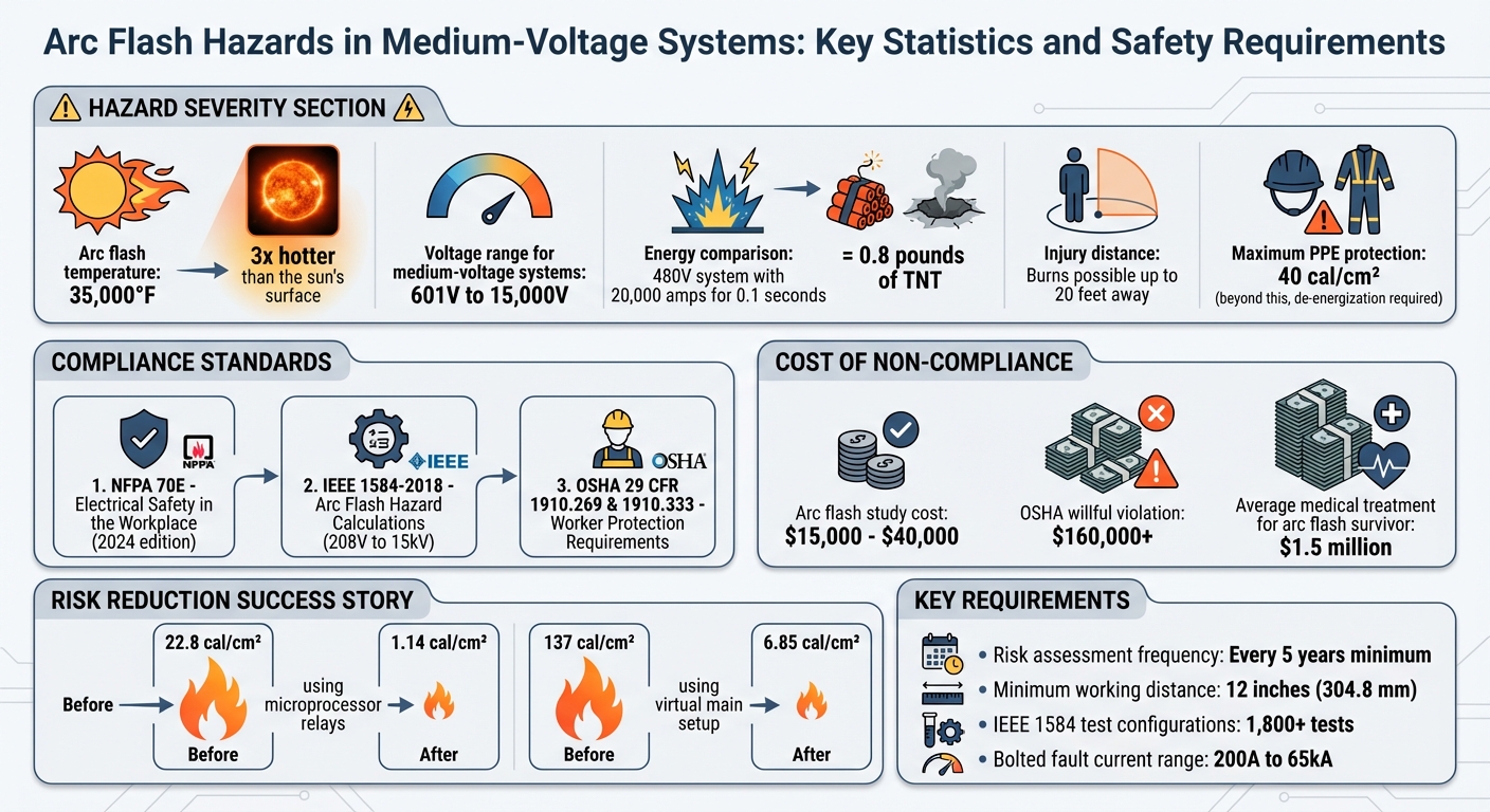
Arc Flash Hazards in Medium-Voltage Systems: Key Statistics and Safety Requirements
Arc fault – Effects mitigation measures in air-insulated medium-voltage switchgear
sbb-itb-501186b
What Is Arc Flash in Medium-Voltage Systems
An arc flash is a sudden electrical explosion that happens when current jumps through the air between conductors or from a conductor to the ground. This creates a plasma arc - a superheated, ionized gas that releases intense heat and light. In medium-voltage systems (ranging from 601 V to 15,000 V), the higher voltage levels make it easier for sparks to form, even without direct contact between components.
The intensity of an arc flash depends largely on two factors: the amount of fault current available and how quickly protective devices can interrupt the fault. In medium-voltage systems, the energy released during an arc flash can be far greater than in low-voltage systems for the same fault duration. This makes equipment like switchgear, motor control centers, and transformer termination points particularly hazardous. The following section explores the common triggers for these dangerous events.
Common Causes of Arc Flash
For an arc flash to occur, three conditions must align: a conductive path between voltage points, sufficient voltage to ionize the air, and an initiating event.
One major cause is human error. Workers might unintentionally touch energized parts due to slipping tools, dropping equipment into live enclosures, or racking circuit breakers in or out while the system remains energized. Skipping proper voltage testing or failing to follow lockout/tagout protocols during system modifications can also lead to accidents.
Equipment failure is another key factor. Over time, insulation may degrade, connections can loosen or corrode, and carbonized tracking can form, creating unintended pathways for current. In transformers, issues like shorted windings or secondary-side faults can generate enough energy to sustain a dangerous arc - especially in systems without a main interrupting device.
Environmental conditions also contribute. Moisture on bus bars, conductive dust on open switchgear, and water intrusion can compromise insulation. Even animals, such as birds or squirrels, can create a conductive path in high-voltage systems.
These factors not only trigger arc flash events but also heavily influence the extent of personal injuries and equipment damage.
Safety and Equipment Damage from Arc Flash
The consequences of an arc flash are severe. The rapid formation of plasma and vaporized metal produces extreme thermal radiation, causing burns, and a pressure wave (arc blast) that can reach supersonic speeds. For example, a phase-to-phase fault in a 480V system carrying 20,000 amps for just 0.1 seconds can release energy comparable to 0.8 pounds of TNT.
While personal protective equipment (PPE) provides some defense, its protection levels are capped at 40 cal/cm². Beyond this point, de-energizing the system becomes the safest approach. The heat radiated from an arc flash can cause life-threatening injuries or even fatalities at distances of up to 20 feet. This highlights the importance of establishing proper arc flash boundaries.
Arc flash incidents can also devastate equipment. Switchgear, transformers, and other critical components may be completely destroyed. On top of repair or replacement costs, the resulting downtime can lead to significant financial losses. This is why reducing arc flash risks is critical - not just for safeguarding lives but also for protecting essential infrastructure.
US Standards for Arc Flash Protection
In the United States, standards and regulations work together to address the dangers posed by arc flash events in medium-voltage systems. Federal workplace safety laws enforced by OSHA, combined with technical standards like NFPA 70E and IEEE 1584, create a comprehensive approach to managing these risks. While OSHA sets the legal framework, it often references NFPA 70E for defining safety measures. Meanwhile, IEEE 1584 provides detailed methods for calculating arc flash hazards. Together, they guide both the assessment of risks and the implementation of protective measures.
NFPA 70E: Electrical Safety in the Workplace

NFPA 70E serves as the cornerstone standard for electrical safety in the U.S., with its 2024 edition currently in use. For medium-voltage systems (601 V to 15 kV), the standard requires an engineered arc flash hazard analysis to determine the incident energy at points where workers may be exposed to energized parts. Equipment must display labels that include the system voltage, arc flash boundary, and either the calculated incident energy with working distance or a specific PPE category.
NFPA 70E also defines protective boundaries - arc flash, limited, and restricted - based on the level of incident energy and proximity to energized components. These boundaries help establish safe working practices.
Arc flash assessments must be reviewed at least every five years or whenever significant system changes occur, such as replacing transformers or modifying feeders. For incident energy levels exceeding 40 cal/cm², NFPA 70E generally prohibits live work due to the extreme danger, requiring de-energization instead.
"An arc flash study is an engineered analysis of your electrical distribution system that calculates incident energy at locations where people may work on or near energized parts and defines safe approach boundaries."
– Hallam-ICS Editorial Team
IEEE 1584: Arc Flash Hazard Calculations
IEEE 1584-2018 is the go-to standard for calculating arc flash hazards in three-phase AC systems ranging from 208 V to 15 kV [13, 18]. Developed from over 1,800 test configurations, it accounts for factors like electrode orientation and enclosure size. For instance, vertical electrodes in a metal box (VCB configuration) result in different energy patterns compared to horizontal electrodes in open air (HOA configuration) [15, 18].
The standard applies to bolted fault currents between 200 A and 65 kA. It includes both predicted and reduced arcing current calculations, using a correction factor for slower protective response times at lower fault levels. A minimum working distance of 12 inches (304.8 mm) is recommended to keep workers outside the arc plasma cloud. For systems exceeding 15 kV, the Lee method - based on theoretical calculations - is preferred over the empirical model. Using actual equipment measurements can further improve the accuracy of risk assessments [17, 18].
OSHA Requirements for Worker Protection
While NFPA 70E and IEEE 1584 provide technical guidelines, OSHA enforces these practices through regulations. Under 29 CFR 1910.269, which governs electric power generation, transmission, and distribution, employers must assess arc hazards, estimate heat energy exposure, and ensure workers wear appropriate protective clothing. According to 29 CFR 1910.333, live parts must be de-energized before work unless doing so is impractical or creates a greater hazard. Equipment that is not locked or tagged out must be treated as energized.
"Conductors and parts of electric equipment that have been deenergized but have not been locked out or tagged ... shall be treated as energized parts."
– OSHA 29 CFR 1910.333
OSHA's General Duty Clause supports NFPA 70E requirements and uses IEEE 1584 for hazard calculations. Under 29 CFR 1910.132, employers must conduct hazard assessments and select the proper PPE. For medium-voltage systems (601 V to 15 kV), OSHA assumes a three-phase arc unless proven otherwise, recommending IEEE 1584 calculation methods. Appendix E to 29 CFR 1910.269 offers further guidance on estimating incident heat energy and choosing arc-rated clothing for different voltage levels.
A key OSHA rule is the prohibition of meltable fabrics like acetate, nylon, polyester, or polypropylene. These materials can melt into the skin during an arc flash, increasing injury severity [19, 20]. However, arc-rated protection is not required for hands when rubber insulating gloves with protectors are used or for feet when heavy-duty leather work shoes are worn.
Arc-Resistant Equipment Design
Arc-resistant equipment is designed to reduce the severity of arc flash incidents by containing faults and directing the resulting energy away from operators. By combining sturdy construction with strict adherence to safety standards, these designs help protect against arc flash hazards. For example, arc-resistant switchgear uses structural features to channel the forces generated during an arc event away from personnel. Insulating barriers further reduce the likelihood of arcing faults by preventing conditions that could trigger them. Together, these strategies align with regulatory guidelines while actively minimizing arc flash risks.
Arc-Resistant Switchgear Features
Arc-resistant switchgear is built to endure the intense forces created by internal arc faults. Its enclosures are engineered to contain flames, molten metal, and rapidly expanding gases during such events. For medium-voltage systems over 600 V, indoor setups require metal-enclosed equipment to limit access and contain potential hazards.
Key design elements include compartmentalization, which separates high-voltage components from low-voltage control equipment using physical partitions. This prevents faults in one section from spreading to others. Sliding components, like rack-mounted circuit breakers, are reinforced to address their vulnerability as potential fault points. Ventilation openings are specifically designed to deflect debris and safely release gases away from operators.
Unused openings in cabinets must be sealed with materials that match the protective level of the equipment’s walls to maintain the arc-resistant rating. Additionally, external elements like water or steam lines should not be placed near metal-enclosed switchgear unless they serve fire protection purposes. Leaks from such lines could compromise insulation and lead to arcing faults.
Finally, insulating barriers are incorporated to provide an extra layer of protection, ensuring that arc faults are less likely to start or spread.
Insulating Barriers and Components
High-quality insulation plays a critical role in preventing the breakdown that leads to arc faults. All splices, joints, and exposed conductor ends should have insulation equivalent to the conductors themselves. This minimizes the chances of phase-to-phase or phase-to-ground faults. Barriers also help by preventing accidental contact between energized and grounded parts, reducing risks from dropped tools or human mistakes.
"The arc behaves like a flexible conductor and consists of ionized air at very high temperature, in the order of 35,000°F - more than three times hotter than the surface of the sun."
– Syed M. Peeran, PhD, PE, CDM Smith
With electric arcs reaching temperatures of about 35,000°F, internal barriers are essential to stop the arc from spreading and causing secondary faults in other equipment. Insulating components also protect energized parts from external triggers, such as rodents or other pests that might enter switchgear enclosures and cause faults. For medium-voltage systems, arcing fault currents can reach approximately 90% of the bolted fault current, making effective insulation crucial to prevent minor issues, like loose connections, from escalating into major faults.
To maintain safety, regular inspection and testing of cable and bus insulation is vital. Defective insulation is one of the leading causes of dangerous arcing. Switchgear enclosures should also be sealed and maintained to keep out pests, and connections should be routinely checked to ensure they remain tight, avoiding localized overheating that could lead to a serious arc flash incident.
Arc Flash Risk Reduction and Compliance
Ensuring worker safety while maintaining operational efficiency in medium-voltage systems takes a structured approach. This involves technical analysis, advanced protective technologies, and consistent maintenance in line with NFPA 70E, IEEE 1584, and OSHA standards.
Performing Arc Flash Risk Assessments
The first step in reducing arc flash risks is conducting a thorough risk assessment, starting with detailed data collection. Document all protective devices - like fuses, breakers, and relays - along with their current settings. Gather single-line diagrams, transformer kVA ratings, impedance values, and primary voltages to provide a complete picture of the system's layout and performance.
Next, calculate bolted fault currents for each bus. These calculations are critical because arcing currents and incident energy levels depend on short-circuit conditions. For medium-voltage systems (601 V to 15 kV), electrode configurations like VCB (Vertical Electrodes in a Metal Box) or VCBB (Vertical Electrodes with an Insulating Barrier) must be identified, as they directly influence arc flash severity.
Using IEEE 1584-2018 equations, calculate incident energy (measured in cal/cm²) at specified working distances. It’s essential to compute both the standard arcing current and a reduced value (typically 85% of the calculated current). Lower currents can result in delayed tripping of protective devices, increasing total incident energy. For most medium-voltage systems, a minimum working distance of 12 inches (304.8 mm) is recommended to keep workers outside the arc plasma cloud.
Once the calculations are complete, create equipment labels that display critical information: arc flash boundaries, incident energy levels, required PPE categories, working distances, and nominal voltage. Reassess the system at least every five years or after significant changes, such as transformer replacements or utility tie additions, as these can invalidate prior studies.
With risk levels quantified, the next step is implementing technologies to mitigate these hazards.
Protection Technologies and Solutions
Microprocessor relays play a key role in reducing incident energy. These devices detect and interrupt faults much faster than older electromechanical relays. Many include arc flash sensors that respond to the light emitted by an arc, enabling nearly instantaneous fault clearing. Maintenance mode switches (also known as ARMS - Arc Reduction Maintenance Systems) allow for instantaneous breaker tripping during maintenance. Remote switching capabilities further enhance safety by letting operators trip breakers from a safe distance.
A real-world example highlights these benefits: Engineers at National Field Services reduced incident energy on a medium-voltage switchgear bus from 22.8 cal/cm² to 1.14 cal/cm² by programming a protective relay with reduced instantaneous settings. They also implemented a "virtual main" setup by adding current transformers to a 2,000 kVA transformer’s secondary side, cutting incident energy on the low-voltage switchgear bus from 137 cal/cm² to 6.85 cal/cm².
"The faster the fault is cleared, the lesser the incident energy resulting in lower arc flash hazards."
– Bibek Karki, Engineering Manager, National Field Services
Additional protective measures, such as current-limiting fuses and arc flash detection relays, further reduce the duration and intensity of arc flash events. These technologies work together to create a safer environment for personnel working on medium-voltage systems.
How to Achieve Compliance
Compliance goes beyond risk assessments and protective technologies - it requires disciplined maintenance and accurate analytical studies. NFPA 70E mandates incident energy analysis, while NFPA 70B (now a mandatory standard as of 2023/2024) requires regular maintenance testing of breakers and relays to ensure their functionality.
"If your breakers are not physically tested and maintained to operate within their specified clearing times, the math in your arc flash study is worthless. The label on your panel becomes a lie."
– Tim Cheung, CTO and Co-Founder, Factory AI
Start by ensuring that system diagrams are up to date. If they’re outdated, creating new CAD drawings is a critical first step. Request utility fault current data as early as possible, as these figures are essential for accurate calculations and can take weeks to obtain.
For a medium-sized manufacturing plant (about 500,000 square feet), the cost of a comprehensive arc flash study typically ranges from $15,000 to $40,000. In contrast, OSHA willful violations can exceed $160,000, and the average medical treatment cost for an arc flash survivor is around $1.5 million.
To maintain compliance, implement predictive maintenance schedules to ensure protective devices operate within their specified clearing times. Transitioning from reactive repairs to scheduled testing not only supports safety but also ensures compliance. Consider upgrading to microprocessor relays with remote operation capabilities to increase working distances and keep personnel outside the arc flash boundary. Reevaluate the incident energy analysis every five years or after any major system modifications.
Some organizations are now using digital twins to simulate electrical system behavior and keep arc flash data current. Integrating this data with computerized maintenance management systems (CMMS) via QR codes on equipment provides maintenance teams with instant access to hazard and PPE information, streamlining safety efforts.
Conclusion
Arc flash hazards in medium-voltage systems pose serious risks to both personnel and equipment, with the potential for rapid, catastrophic damage. The extreme heat generated during an arc flash can cause severe injuries and lead to sudden equipment failure, making safety precautions essential. Compliance with standards like NFPA 70E, IEEE 1584, and OSHA regulations goes beyond meeting legal requirements - it's about safeguarding lives and preserving valuable assets.
To address these risks, a three-step strategy is key: conduct regular arc flash risk assessments following IEEE 1584-2018 guidelines, invest in advanced protective technologies to reduce incident energy, and ensure system documentation is current while performing consistent maintenance. Protective solutions such as microprocessor relays, arc-resistant switchgear, and remote operation tools are more effective at minimizing incident energy than relying solely on personal protective equipment. This proactive approach enhances safety while supporting operational reliability.
"Effective arc flash mitigation is attainable through advanced protective relays, enhancing safety without sacrificing system reliability." – Bibek Karki, Engineering Manager, National Field Services
FAQs
When does IEEE 1584 apply, and when is the Lee method used instead?
IEEE 1584-2018 is the standard used for determining arc flash incident energy and boundaries in three-phase AC systems. It applies to systems operating between 208 V and 15 kV, with fault currents ranging from 200 A to 106,000 A. For systems that fall outside this range - such as those with voltages exceeding 15 kV or configurations not covered by IEEE 1584 - the Lee method serves as an alternative approach for calculations.
What system data is required for an arc flash study?
Before diving into an arc flash study, you'll need to gather specific system data. Key information includes the operating voltage (ranging from 208 V to 15,000 V), bolted fault current limits, electrode configuration, gap distances, and other system parameters like fault current and arcing voltage. These details are crucial for performing precise calculations based on the IEEE 1584-2018 standard.
How can I lower incident energy without replacing my switchgear?
To lower incident energy without replacing your switchgear, you can explore approaches such as lowering the available fault current, reducing fault clearing time, or increasing the working distance. One modern solution is the use of high-speed arc flash detection relays, which can respond in milliseconds to significantly reduce arc duration. Additionally, fine-tuning protection settings through system coordination and leveraging embedded analytics can help minimize risks, all while maintaining your current switchgear setup.





