
Top 5 Medium-Voltage Testing Protocols Explained
Failures in medium-voltage equipment (1kV–35kV) can lead to downtime, safety issues, and high repair costs. Proper testing ensures equipment reliability, safety, and compliance with standards like NEC and NFPA 70. Here are the five key testing protocols you need to know:
- Dielectric Withstand (Hi-Pot) Testing: Applies high voltage to check insulation strength. Detects early failures and insulation weaknesses.
- Insulation Resistance (Megger) Testing: Non-destructive test to measure insulation health. Identifies moisture, contamination, and aging issues.
- Contact Resistance Testing: Measures resistance in current paths to detect corrosion, arcing, or wear in switchgear and circuit breakers.
- Primary Injection Testing: Simulates fault conditions to verify the performance of protection systems like circuit breakers and CTs.
- Partial Discharge (PD) Testing: Detects localized insulation breakdowns, revealing hidden defects before they escalate.
These tests ensure equipment operates safely and efficiently while meeting compliance requirements. Each method addresses specific issues, offering a complete picture of your system's health. Regular testing is essential for long-term reliability and avoiding costly failures.
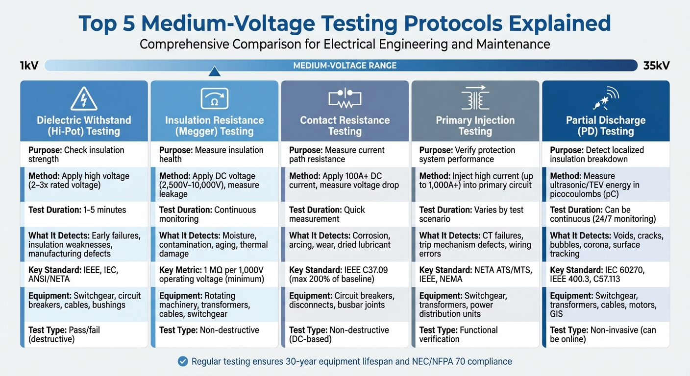
5 Essential Medium-Voltage Testing Protocols Comparison Chart
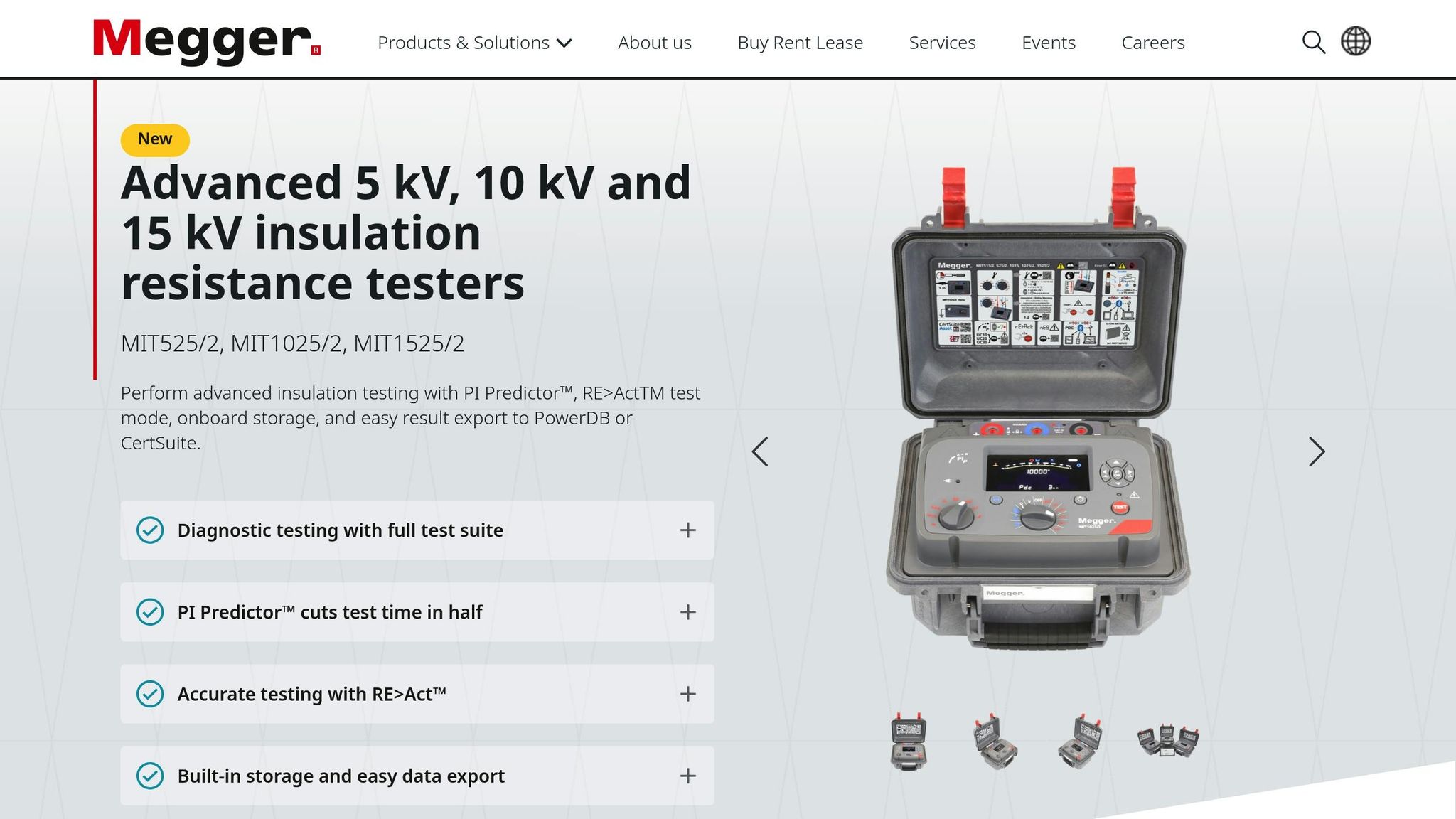
MV cable IR testing with Mit1025 Insulation Resistance Tester
sbb-itb-501186b
1. Dielectric Withstand (Hi-Pot) Testing
Dielectric withstand testing, often referred to as Hi-Pot testing, involves applying a controlled high voltage to equipment - far exceeding its normal operating voltage. The goal? To ensure the insulation can withstand extreme conditions without breaking down. It's a straightforward pass/fail test that uncovers insulation weaknesses.
Safety and Compliance with Standards
Hi-Pot testing plays a key role in meeting IEEE, IEC, and ANSI/NETA standards by using specific overvoltage levels for set durations. For instance, equipment rated for 13,800 V undergoes a factory test at 36,000 V, while maintenance testing applies a lower voltage of 27,000 V. Typically, AC withstand tests apply 2 to 3 times the rated voltage for 1 to 5 minutes.
| Rated Operating Voltage | AC Factory Proof Test (V) | AC Maintenance Test (V) |
|---|---|---|
| 4,160 | 19,000 | 14,250 |
| 13,800 | 36,000 | 27,000 |
| 23,000 | 60,000 | 45,000 |
| 34,500 | 80,000 | 60,000 |
These standardized conditions ensure consistency and help identify potential insulation problems effectively.
Effectiveness in Identifying Faults or Weaknesses
Hi-Pot testing is particularly effective during the "infant mortality" phase - typically the first year of operation - when early insulation failures from manufacturing defects or installation damage are most likely to occur. As Steve Park, Technical Services Manager at Electrical Reliability Services, points out:
"Withstand testing could likely cause the cable to fail in the near future during normal operation."
Leakage current, measured in microamperes (µA), is monitored during the test. A sudden surge in current signals insulation breakdown. To ensure safety before applying high voltage, an insulation resistance test should be performed first.
Applicability to Medium-Voltage Equipment
Hi-Pot testing is widely used for medium-voltage equipment, including switchgear, circuit breakers, cables, and bushings. For extruded cables like XLPE, Very Low Frequency (VLF) testing at 0.1 Hz has become the industry standard. Unlike DC testing, VLF testing effectively detects defects without causing damage. In fact, ANSI/NETA MTS 2023 specifically recommends VLF withstand testing for medium- and high-voltage shielded cables. These advancements highlight the evolving methods for testing in both factory and field environments.
Field and Factory Testing Relevance
Factory testing uses higher voltages to catch manufacturing defects, whereas field maintenance testing applies reduced voltages - about 65% of the original factory test values for cables - to evaluate the insulation's condition without overloading it. Before field testing, terminations should be cleaned, and auxiliary equipment disconnected to prevent interference. Post-DC testing, it’s crucial to ground the equipment for at least four times the test duration to safely discharge any residual voltage. Together, these practices underscore the importance of Hi-Pot testing in maintaining the reliability of medium-voltage equipment.
2. Insulation Resistance (Megger) Testing
Insulation resistance testing evaluates how effectively electrical insulation resists current flow by applying a controlled DC voltage and measuring leakage current. Unlike Hi-Pot testing, this method is non-destructive and provides measurable data on insulation health without risking equipment damage. It's widely used to detect issues like moisture, contamination, and aging before they escalate into major problems.
Safety and Compliance with Standards
This testing method adheres to strict safety and operational standards to protect both operators and equipment. Organizations like IEEE, IEC, and NETA recommend DC test voltages of 2,500V or 5,000V for medium-voltage equipment, with up to 10,000V for equipment rated above 4,160V. The "one-megohm rule" is a key guideline, requiring at least 1 MΩ of insulation resistance for every 1,000 volts of operating voltage. Electrical engineer Edvard Csanyi explains:
"Insulation resistance should be approximately one megohm for each 1,000 volts of operating voltage, with a minimum value of one megohm."
Temperature can significantly affect readings, often varying by a factor of 2 for every 10°C change. To address this, IEEE 43 mandates normalizing all readings to a standard reference temperature of 40°C for consistency across different conditions. Additional metrics like the Polarization Index (PI) and Dielectric Absorption Ratio (DAR) are also used to evaluate insulation health. A PI below 1.0 signals a critical issue for most rotating machinery, while values between 2.0 and 4.0 indicate good condition.
Effectiveness in Identifying Faults or Weaknesses
Megger testing is highly effective at pinpointing issues such as moisture, contaminants, and chemical breakdowns. It also detects thermal damage caused by prolonged overheating, aging, and physical damage like nicked wires, cracks from vibration, or abrasion. For cables, this testing identifies specific problems like water trees, voids, and termination failures due to poor sealing. In transformers, it evaluates insulation integrity across primary-to-ground, secondary-to-ground, and inter-winding connections.
However, a single test result only provides a snapshot. Tracking trends over time is essential - a consistent decline in readings, even if values remain above minimum thresholds, could indicate an impending failure. Initial "as-found" values recorded during commissioning serve as a baseline, with a 50% drop from these values signaling serious degradation. When testing in environments with high humidity or contamination, using the tester's guard terminal can help eliminate surface leakage currents for more accurate results.
Applicability to Medium-Voltage Equipment
This testing method is versatile, covering a range of medium-voltage equipment such as rotating machinery (per IEEE 43), switchgear buses, transformers, and power cables (per IEEE 400). Before starting the test, it's crucial to disconnect sensitive components like power electronics, surge protection devices, and sensors to prevent damage from the high DC voltage. After testing, ensure the equipment is fully discharged to avoid safety risks from stored capacitive energy.
Field and Factory Testing Relevance
In factory settings, insulation resistance testing helps uncover manufacturing defects or shipping damage, providing a baseline for future evaluations. In the field, maintenance testing identifies wear and tear caused by environmental factors like moisture, contamination, and operational stresses such as load cycling. Routine tests, such as those for circuit breakers, are typically conducted every three years. These tests play a critical role in assessing insulation resistance and preparing for further evaluations to ensure equipment reliability.
3. Contact Resistance Testing
Contact resistance testing, often referred to as Ductor testing, involves measuring the resistance of the primary current path by applying a high DC current and recording the resulting voltage drop. This test is essential for evaluating switchgear and circuit breakers, as it helps identify high-resistance points caused by factors like repeated arcing, corrosion, or aging lubrication. Elevated resistance can lead to I²R losses, which generate heat, degrade components, and potentially cause arcing, single phasing, or even catastrophic fires. Its precision and alignment with standards make it an indispensable part of medium-voltage equipment evaluations.
Safety and Compliance with Standards
The IEEE C37.09 standard governs contact resistance testing for AC high-voltage circuit breakers rated above 1,000 V. According to this standard, resistance values should not exceed the original factory baseline by more than 200%. Additionally, the NETA Maintenance Testing Specifications require resistance readings to stay within 50% of those from adjacent phases. To ensure accuracy when testing medium-voltage equipment, a test current of at least 100 A DC is recommended. Standard digital multimeters are insufficient for overcoming surface films and delivering reliable measurements.
Effectiveness in Identifying Faults or Weaknesses
Contact resistance testing is particularly effective at uncovering issues like contact pitting, misalignment, corrosion, and degraded lubricants at pivot points. James R. White, Director of Training at Shermco Industries, highlights its importance:
"One of the primary reasons to perform the contact resistance test is to determine the condition of the pivot point between the moving and stationary contacts."
For instance, dried lubricant can elevate resistance, leading to excessive heat, accelerated wear, or even seizing of components. Typical resistance values for 15 kV circuit breakers range from 200 µΩ to 250 µΩ. For low-voltage breakers, readings above 300 µΩ often indicate problems, while healthy contacts usually measure around 100 µΩ or less. When paired with Hi-Pot and Megger tests, contact resistance testing provides a comprehensive assessment of electrical connection reliability.
Applicability to Medium-Voltage Equipment
This test is suitable for circuit breakers, disconnecting switches (isolators), busbar joints, and other primary current-carrying connections in medium-voltage switchgear. It is performed using a digital low-resistance ohmmeter (DLRO) or micro-ohmmeter while the equipment is in the closed position, measuring between bushing terminals. The Kelvin (4-wire) method is used to eliminate the influence of test lead resistance, ensuring accurate results.
Field and Factory Testing Relevance
Factory tests establish baseline resistance values for new equipment, serving as a benchmark for future comparisons. In the field, contact resistance testing is conducted during initial acceptance and approximately every three years as part of preventive maintenance programs to track deterioration over time. Before testing, ensure the switchgear is thoroughly cleaned to prevent surface contaminants from skewing the results. While contact resistance testing is DC-based and generally safe, it must always be performed on de-energized and properly grounded equipment to guarantee safety.
4. Primary Injection Testing
Primary injection testing involves introducing a high-level current directly into the primary circuit to simulate fault conditions. This process ensures the entire protection system - such as CTs, trip units, coils, and mechanical tripping mechanisms - functions properly under realistic load scenarios. It’s a critical step in meeting stringent safety and performance standards.
Safety and Compliance with Standards
This testing method adheres to NETA ATS and MTS standards, confirming that equipment operates within acceptable time-current tolerances and safely extinguishes arcs, as outlined by IEEE and NEMA guidelines. Given the high currents involved, all equipment must be de-energized and securely grounded during testing. Keep in mind that test sets for larger equipment are hefty, weighing between 300–500 lbs, and typically require power inputs of 240 VAC or three-phase 277/480 VAC.
Effectiveness in Identifying Faults or Weaknesses
Primary injection testing excels at uncovering issues like circuit breaker failures, CT malfunctions, cable insulation problems, wiring errors, CT polarity mismatches, and defective trip mechanisms. Edvard Csanyi highlights its importance:
"Primary injection testing is, however, the only way to prove correct installation and operation of the whole of a protection scheme."
This method doesn’t just rely on theoretical calculations - it physically verifies that breakers can interrupt current and extinguish arcs. To streamline troubleshooting, it’s wise to conduct primary injection testing after secondary injection tests, isolating potential issues in voltage transformers, current transformers, or wiring. When paired with Hi-Pot and Megger tests, it completes a thorough evaluation of medium-voltage equipment.
Applicability to Medium-Voltage Equipment
Primary injection testing is widely used for equipment like switchgear, transformers, and power distribution units in utility, industrial, and commercial environments. Portable injection transformers typically deliver around 10 V and 1,000 A, while advanced PC-controlled systems can inject currents up to 200 A. It’s crucial to ensure that the injected current remains within the MCCB’s rated interrupting capacity to avoid damage.
Field and Factory Testing Relevance
In factory settings, primary injection testing verifies that new equipment meets the manufacturer’s specifications. In the field, it helps identify wear and tear in breaker contacts and mechanisms. While these tests can be time-consuming and require equipment outages, they are vital for ensuring the reliability of medium-voltage protection systems. To minimize disruptions, schedule these tests during commissioning or routine maintenance periods.
5. Partial Discharge (PD) Testing
After primary injection testing, Partial Discharge (PD) testing provides an even earlier indication of insulation wear and tear.
PD testing identifies localized electrical breakdowns that happen when insulation gaps partially connect conductors. These discharges typically occur in areas where the electric field is highly stressed, such as in air-filled voids, cracks within solid insulation, or bubbles in liquid dielectrics.
Safety and Compliance with Standards
PD testing adheres to strict standards to ensure accuracy and safety. The IEC 60270:2025 outlines guidelines for measuring PD, while IEEE and ANSI/NETA standards specify calibration and measurement protocols. For specific equipment, IEEE 400.3-2022 focuses on shielded power cable systems, IEEE C57.113-2023 applies to liquid-filled transformers, and IEEE C57.160-2023 addresses bushings and instrument transformers.
PD intensity is measured as "apparent charge" in picocoulombs (pC). According to ANSI/NETA MTS 2019, ultrasonic energy levels exceeding 6 dBuV require immediate attention.
Effectiveness in Identifying Faults or Weaknesses
PD testing uncovers insulation issues that other methods might miss. Different types of PD - such as internal PD detected with TEV sensors and surface PD identified using ultrasonic sensors - point to specific insulation problems. Corona PD, which occurs in gaseous environments surrounding conductors, is especially common in outdoor setups.
For instance, in October 2023, a critical 11 kV switchboard equipped with 24/7 PD monitoring showed a rapid increase in PD amplitude on a voltage transformer. Upon emergency inspection, severe insulation damage was found, allowing for a planned replacement. This proactive approach prevented a major failure and avoided customer outages. Additionally, poor workmanship at cable terminations, which accounts for two-thirds of medium-voltage cable failures, highlights the importance of PD testing during commissioning.
Complementary methods like high-frequency current transformers (HFCT) on cable ground shields, TEV sensors for voltage spikes, ultrasonic testing for airborne energy, and UHF radio detection for broadband spikes further enhance the ability to pinpoint defects.
Applicability to Medium-Voltage Equipment
PD testing is suitable for a wide range of equipment operating between 3 kV and over 700 kV. This includes switchgear, transformers, cables (both paper-insulated and extruded), gas-insulated switchgear (GIS), and motors. For high-risk assets, combining permanent PD monitoring with annual testing is a smart approach to track rapid defect progression.
In one case, a network operator conducting annual PD tests found an ultrasonic source in the cable box of an 11 kV ring main unit. Despite the detection, the asset failed within the same year because the defect's progression-to-failure interval was only 7 to 19 months. This example underscores how PD testing plays a crucial role in maintaining the reliability of medium-voltage systems.
Field and Factory Testing Relevance
The industry is increasingly moving toward online, non-invasive PD testing, which evaluates energized equipment without the need for shutdowns. However, offline testing - requiring an external voltage source and equipment downtime - remains essential for creating controlled conditions. For critical assets with short potential-to-failure (P–F) intervals, typically 1–2 months, operators are shifting from periodic testing to 24/7 permanent monitoring.
Before testing, always calibrate the PD measuring circuit to establish the scale factor for apparent charge. Combining TEV and ultrasonic testing ensures thorough coverage and reliable results.
How Testing Protocols Affect Equipment Purchases
When you're investing in medium-voltage breakers, transformers, or switchgear, testing protocols play a key role in ensuring the equipment can safely meet its expected 30-year lifespan. These tests confirm that insulation systems can handle the operational stresses they'll face over time. This is especially important now that the responsibility for medium-voltage distribution has shifted from utilities to building and site owners.
As the owner, you're responsible for making sure your equipment complies with the National Electrical Code (NEC) and NFPA 70 standards. UL Solutions highlights the importance of certification:
Receiving UL certification is an effective way to satisfy insurance requirements and to help ensure a code‐compliant installation.
Thorough testing not only ensures safe operation but also helps you make better purchasing decisions. For example, when browsing platforms like Electrical Trader (https://electricaltrader.com) for breakers or transformers, look for units accompanied by Routine Test reports. These reports confirm the equipment passed factory tests like high-voltage withstand and partial discharge checks.
However, factory tests alone aren't enough. Real-world conditions during shipping or installation can impact performance. Consider this: in 2019, a solar farm skipped standard Very Low Frequency (VLF) testing to save time, opting instead for a basic insulation resistance check. Just three days after energization, a rainstorm triggered a phase fault, resulting in $150,000 in downtime and repair costs. The cause? A 1 mm insulation gouge from a backhoe - something a proper VLF test would have caught. As Richard Zi, General Manager at ZW Cable, wisely points out:
It is infinitely better to blow a weak joint during a Tuesday morning test than during a Friday night peak load.
Beyond initial testing, commissioning is essential for long-term reliability. Establishing baseline data helps track equipment degradation over time. For instance, a power factor below 1% signals healthy insulation in switchgear, while 15 kV circuit breakers should show contact resistance between 200 and 250 microohms (µΩ). Comprehensive commissioning tests are surprisingly cost-effective, typically accounting for less than 1% of the project budget. For critical systems like those in hospitals, data centers, or manufacturing facilities, this small investment can prevent catastrophic failures and the massive costs of emergency repairs and lost productivity.
Conclusion
Medium-voltage testing protocols play a critical role in ensuring electrical system safety by identifying insulation defects that can’t be detected through visual checks. These hidden issues, like micro-insulation flaws, can lead to serious failures if left unchecked. Without proper testing, operators are left guessing whether their equipment will function as intended.
The five key testing methods - Dielectric Withstand, Insulation Resistance, Contact Resistance, Primary Injection, and Partial Discharge - work in tandem to assess both the electrical and mechanical health of equipment. Even though some equipment is designed to last up to 30 years, factors like environmental conditions can accelerate wear and tear. Regular testing helps monitor equipment health, allowing for timely maintenance before problems escalate. This proactive approach not only supports compliance but also strengthens long-term maintenance planning.
Compliance with standards has become a requirement rather than a suggestion. With the introduction of NFPA 70B-2023, maintaining electrical equipment is now an enforceable obligation. As the responsibility for medium-voltage distribution has shifted from utilities to property owners, adhering to NEC and NFPA 70 guidelines is essential. Proper testing protocols and third-party certifications also help meet insurance requirements, adding another layer of protection for your assets.
Modern maintenance strategies now emphasize performance-based diagnostics. Tools like Partial Discharge testing provide measurable data to predict an asset’s remaining lifespan, enabling informed decisions about capital investments and replacement schedules. This foresight helps avoid unnecessary equipment retirements and mitigates the risk of unexpected failures that could disrupt operations.
FAQs
What test should be performed first during commissioning?
The initial step in commissioning involves a physical and visual inspection. This step confirms that the installation has been carried out correctly, checks the integrity of all components, and ensures everything aligns with the required specifications. It's an essential process for spotting any potential problems before moving on to more advanced testing.
How often should medium-voltage equipment be retested?
Medium-voltage equipment needs regular testing to ensure it operates safely and reliably. The frequency of these tests depends on several factors, including the manufacturer's recommendations, industry standards like NETA, and the equipment's usage history. Testing schedules can vary, often ranging from annual inspections to checks at other prescribed intervals. Sticking to these guidelines helps maintain performance and reduces the risk of unexpected failures.
When should I choose online PD monitoring vs offline PD testing?
For continuous, real-time assessment during regular operations, choose online PD monitoring. This approach identifies insulation problems early without requiring downtime, making it perfect for critical equipment like transformers, cables, and switchgear.
If you’re planning a scheduled outage, go with offline PD testing. This method offers detailed diagnostics in a controlled setting, giving you a comprehensive look at insulation health. It’s especially useful for routine maintenance or confirming the condition of your assets.


