
Emerging Trends in Wind Power Conversion Tech
Wind power conversion in 2026 is moving in one clear direction: bigger turbines, stricter grid rules, and more power electronics. If I were buying or specifying wind equipment today, I’d focus on five things first: full converters for 10–15+ MW turbines, SiC devices for smaller and lighter converter systems, VSC-HVDC for long-distance export, dry-type 66 kV+ transformer setups, and grid-forming controls in converter RFPs.
Here’s the short version:
- Type IV full-converter systems now lead in large onshore and offshore turbines because they process 100% of turbine output and give better control over voltage, frequency, and fault response.
- DFIG systems still fit some onshore projects under 6 MW, mainly because only about 30% of turbine output passes through the converter.
- SiC MOSFETs can switch at about 30 kHz versus 3 kHz for silicon IGBTs, which can cut passive component volume by about 4.52x.
- VSC-HVDC is the main export choice for long-haul wind transmission. A current U.S. example is the SunZia project, with a 550-mile, ±525 kV HVDC line and up to 3,000 MW transfer capacity.
- Grid-forming controls matter more as weak-grid connections increase, since they support voltage, frequency, and black-start functions.
- Converter reliability is still a pain point, with failure rates near 0.21 failures per MW per year, so high-speed logs, thermal sensing, and AI-based diagnostics matter more now.
- SST and MVDC setups are still early, but they may cut offshore platform needs and trim power-chain losses.
Wind Power Converter Fundamentals: Topologies, Advantages, and Key Requirements Explored | Infineon
sbb-itb-501186b
Quick comparison
| Topic | What I’d watch in 2026 | What it means for buyers |
|---|---|---|
| Turbine converter type | Type IV full converters | Better grid control for large turbines |
| Semiconductors | SiC supply, cost, 3.3 kV class limits | Lock supply early if SiC is required |
| Export system | VSC-HVDC for long distance | Better fit for remote wind projects |
| Transformers | Dry-type, cast-resin, 66 kV+ | Match specs to nacelle/tower use |
| Controls | Grid-forming over grid-following in weak grids | Add GFM to bid specs |
| Reliability | Fast logs, thermal data, ML fault tools | Lower downtime and better service planning |
So, if I had to put the whole article into one line, it would be this: wind conversion is shifting from simple hardware choice to full system choice - converter, controls, transformer, export path, and monitoring all need to work together.
Converter and Semiconductor Trends Driving Higher Power Density
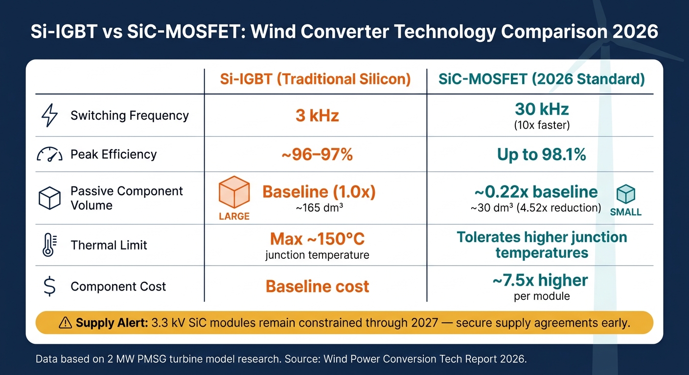
Si-IGBT vs SiC-MOSFET: Wind Converter Technology Comparison 2026
Multilevel Converter Topologies for Multi-MW Turbines
With Type IV turbines now leading in larger projects, the next hurdle is pretty clear: how do you push power density higher without eating into thermal headroom? That’s why multilevel converter topologies like NPC, ANPC, and MMC are showing up more often in multi-megawatt wind systems.
MMC designs stand out in offshore HVDC setups. Instead of forcing all power conversion through a single stage, they spread it across many submodules. That makes it easier to scale to very high voltages while still supporting strong fault ride-through. In practical terms, DC backbone networks built into turbine architecture could remove the need for offshore substation platforms, which often make up 10% to 15% of project CAPEX.
| Topology | Voltage Capability | Key Advantage | Typical Wind Use Case |
|---|---|---|---|
| NPC / ANPC | Medium | Lower harmonic distortion | Standard multi-MW onshore |
| MMC | High / Scalable | Easy scalability; fault ride-through | Offshore HVDC, 15 MW+ turbines |
| Solid-state transformer (DC-DC) | Medium to High | Can reduce or remove transformer stages | Series-DC offshore collection |
So the topology decision now comes down to a few hard limits: voltage rating, fault ride-through needs, and how much room is available in the nacelle.
Hybrid setups are moving forward too. Series-connected Diode Rectifier Units paired with MMCs, often called DRU-MMC, are being deployed in large offshore HVDC systems to improve startup coordination and stabilize DC voltage. One detail matters a lot here: using DC voltage control can hold DC voltage ripple to 2.9%, versus 14.4% in fixed AC voltage control schemes.
SiC Power Devices vs. Traditional Silicon Switches
Multilevel converters only shrink the footprint if the switching devices can keep up. That’s where SiC MOSFETs change the game. They can switch at up to 30 kHz, while conventional IGBTs sit at around 3 kHz. That jump in frequency cuts the size and weight of passive filter parts, with total passive component volume dropping by about 4.52 times.
SiC also gives engineers more thermal room to work with. Traditional silicon devices are generally capped at a maximum junction temperature of around 150°F, while SiC devices can handle higher junction temperatures, which makes smaller or simpler cooling systems possible. At the system level, SiC-based solid-state transformer architectures using 3.3 kV SiC MOSFETs have reached peak efficiencies of 98.1%.
| Feature | Si-IGBT (Traditional) | SiC-MOSFET (2026) |
|---|---|---|
| Typical Switching Frequency | 3 kHz | 30 kHz |
| Peak Efficiency | ~96–97% | Up to 98.1% |
| Thermal Limit | Max ~150°C junction temp | Tolerates higher junction temperatures |
| Passive Component Volume | Baseline (1.0x) | ~0.22x (4.52x reduction) |
| Component Cost | Baseline | ~7.5x higher per module |
The tradeoff is cost and supply. SiC modules still run about 7.5 times more than comparable silicon IGBT modules, and supply of the 3.3 kV class remains the main bottleneck through at least 2027. So yes, the performance is there, but scaling deployment is still tied to what the market can actually deliver.
Compact Converter Design and Advanced Cooling Methods
When you’re dealing with heat in multi-megawatt converters, liquid cold plates still do the best job. They offer much lower thermal resistance than air cooling. At the same time, the EU F-Gas Regulation is pushing interest toward air-cooled SiC power modules, mainly because they simplify the thermal system and cut long-term maintenance risk.
In a wind turbine, space is never cheap. Every cubic foot you save in the converter makes nacelle and tower integration easier. Research based on a 2 MW PMSG turbine model shows just how much size drops when a system moves from 3 kHz Si-IGBT switching to 30 kHz SiC-MOSFET switching:
| Component | Volume at 3 kHz | Volume at 30 kHz |
|---|---|---|
| Inverter-side Inductor | ~140 dm³ | ~20 dm³ |
| Grid-side Inductor | ~20 dm³ | ~5 dm³ |
| Filter Capacitor | Negligible | Negligible |
| Heat Sink (at 25°C) | ~5 dm³ | ~5 dm³ |
| Total Passive Volume | ~165 dm³ | ~30 dm³ |
The heat sink barely changes, but the other parts get much smaller. That means a converter that’s easier to fit inside tight nacelle and tower layouts. And once the converter gets smaller, the knock-on effects show up fast in transformer design and in the collection system too. Those space limits are what push the next set of design changes.
Transmission, Transformers, and Collection Systems for Larger Wind Projects
As converters get smaller, the bottleneck moves downstream to export systems, transformers, and substations. That means export architecture is now one of the biggest design calls in a large wind project.
AC, HVDC, and MVDC Collection and Export Options
For projects near shore, conventional AC collection still works well. But over long distances, HVDC now has the edge because line losses stay lower and voltage control is stronger.
A recent U.S. example shows how fast VSC-HVDC is moving into utility-scale use. Pattern Energy's SunZia Wind Project in New Mexico, which entered commercial operation in June 2026, uses a 550-mile, ±525 kV HVDC corridor to send up to 3,000 MW to California's grid (CAISO). It is the largest Voltage Source Converter (VSC) installation in the U.S.
VSC is favored over older Line-Commutated Converters (LCC) for a simple reason: it gives operators more control. It can independently control active and reactive power, supports black-start capability, and doesn't need a strong existing AC grid at the receiving end.
Further out, MVDC and series-DC collection setups are being studied as a way to remove offshore AC substations altogether. That's a big deal because those platforms can make up 10% to 15% of project CAPEX. Here's how the main options stack up:
| Feature | AC Collection/Export | HVDC (VSC) Export | MVDC/Series-DC (Emerging) |
|---|---|---|---|
| Losses | High over long distances | Low line losses | Potential 2–4% reduction in conversion losses |
| Controllability | Limited reactive power control | Independent active/reactive power control | High flexibility via SSTs |
| Grid Support | Standard | Supports black-start, weak grids | Galvanic isolation per turbine |
Solid-State and Medium-Frequency Transformers
The next target isn't just long-distance export. It's the substation itself.
Solid-state transformer, or SST, designs built around 3.3 kV SiC MOSFETs make series-DC collection possible, with each turbine tied straight into a DC network. In plain terms, that can remove the need for large offshore AC platforms. These designs have reached peak efficiencies of 98.1% and can trim conventional offshore power-chain losses, which usually sit around 4% to 8%, by 2 to 4 percentage points.
The catch is cost and supply. Material costs are about €46,500 per MW, and commercial rollout is still held back by the supply chain for 3.3 kV SiC MOSFETs. Wolfspeed and Infineon capacity are cited as the main bottleneck through 2027. Cooling and insulation are still tough engineering problems too, especially offshore, where modular systems sound great on paper but are harder to service when access is limited.
For turbines in the 15–20 MW+ range, a more immediate shift is already happening. Dry-type, or cast-resin, transformers are becoming the standard for nacelle and tower mounting, replacing oil-immersed units. They are fire-safe, resist vibration well, and fit the 66 kV+ collection voltages these larger turbines need. At the same time, amorphous metal cores are making their way into wind transformers to cut no-load losses by up to 70% compared with conventional silicon-steel cores.
How Equipment Specifications Are Changing
These design shifts are now showing up directly in procurement specs. Large wind projects are moving toward:
- 66 kV+ collection voltages
- K-13 to K-20 transformer ratings
- C5-M marine coatings
- SF6-free switchgear
That last item is already showing up in live contracts. In June 2026, 50Hertz awarded Siemens Energy the North Sea Connector 2 contract for a 2 GW offshore grid system, and the spec called for SF6-free switchgear.
For buyers, this changes the sourcing game. Transformers, switchgear, and HVDC equipment now need to meet a much higher bar.
Grid-Forming Control, Reliability, and Digital Monitoring
As converters get smaller and grid rules get tougher, software matters just as much as silicon. Better hardware still counts, of course. But now the control layer has a huge say in grid behavior and turbine uptime.
Grid-Following vs. Grid-Forming Wind Converters
Grid-following (GFL) converters sync to an existing grid voltage through a Phase-Locked Loop (PLL). That works well when the grid is strong. In weak grids, though, PLL-based converters can oscillate and lose stability.
Grid-forming (GFM) converters work differently. They behave like voltage sources and set their own reference. They sync on their own, use DC-link or rotor energy for short-term support, and regulate voltage and frequency without needing an outside signal. They can also black-start a dead grid, which GFL converters cannot do.
| Feature | Grid-Following (GFL) | Grid-Forming (GFM) |
|---|---|---|
| Control Mode | Current source | Voltage source |
| Grid Dependency | Requires a stable external AC voltage | Autonomous; can operate in islanded or weak grids |
| Voltage Support | Passive; follows grid | Active regulation of magnitude and frequency |
| Inertia Response | None inherent; requires synthetic loops | Provides virtual inertia |
| Black-Start | Not capable | Capable |
| Typical Deployment | Strong grids with high inertia | Microgrids, weak grids, black-start scenarios |
Advanced GFM controls use VSG and configurable droop to tune inertia and damping. And this is not just theory on a slide deck. One measured result shows that advanced GFM DC voltage control can hold MMC DC voltage ripples to 2.9%, versus 14.4% under fixed AC voltage control.
That move in control design has a direct effect on reliability, diagnostics, and plant cybersecurity.
Failure Modes, Lifetime Modeling, and Condition Monitoring
Power converters are among the most failure-prone parts of a wind turbine.
"Power converters are among the subsystems of wind turbines that are most susceptible to failure and, thus, cause considerable costs and yield losses." - Timo Lichtenstein, Fraunhofer Institute for Wind Energy Systems IWES
Power converter failure rates are estimated at about 0.21 failures per MW of capacity per year. The main drivers are thermal cycling, moisture ingress, capacitor wear, and corrosion in control electronics.
One-minute SCADA logs are often too blunt for early fault detection. By the time you spot a problem there, the useful clues may already be gone. That’s why high-resolution "fast logs" matter. They capture data at 4.5 kHz, covering from 350 ms before to 200 ms after a fault trigger.
That level of detail helps technicians find the root cause and figure out which spare parts they need before heading to the site. For offshore wind, where each trip can turn into a major service event, that can save time and cut downtime in a very practical way. Machine-learning models are also being used to classify faults and predict repairs. AI-driven platforms now support 24/7 remote monitoring and condition-based maintenance under long-term service agreements.
| Monitoring Strategy | Lifetime Impact | Complexity | Failure Mode Addressed |
|---|---|---|---|
| Thermal Sensing | High | Medium | Semiconductor wear, thermal cycling |
| Partial Discharge Monitoring | High | High | Insulation stress in transformers |
| Digital Diagnostics (Fast Logs) | Medium | Low | General converter faults, downtime reduction |
| Impedance Monitoring | Medium | Medium | DC-link capacitor degradation |
| Digital Twins / AI | Very High | High | System-wide predictive maintenance |
Cybersecurity and Digital Control in Wind Plants
The same digital tools that improve diagnostics also give attackers more ways in. This is not just an IT issue tucked away in a back office. If a converter control system is compromised, grid stability can be at risk.
Buyers should ask for a few basics up front:
- Encrypted communications
- Secure remote access
- Intrusion-detection support
In short, digital control now sits right at the center of converter performance, fault response, and plant security.
Research Outlook and Conclusion
Where Wind Conversion Research Is Headed Next
After converter hardware, the next move is system integration and procurement-ready architectures. Research is now leaning toward integrated AC/DC architectures that treat the generator and converter as a single system. That shift matters because it changes how projects are designed from the start, not just how parts are selected.
SSTs could, over time, cut down or even remove offshore AC substations, which would change project economics in a big way. At the same time, SiC supply is still tight through 2027, with added pressure around 200 mm wafers.
Key Takeaways for U.S. Electrical and Industrial Buyers
These R&D trends are already shaping how buyers should specify wind equipment. Grid-forming capability is turning into a baseline requirement for large-scale projects as grid operators try to replace the stability once supplied by synchronous generation. SiC-based modules are starting to push out silicon IGBT architectures, with gains in efficiency and lower nacelle mass. And for projects located far from load centers, VSC-HVDC is now the reference architecture.
For U.S. buyers, the practical takeaway is pretty simple:
| Technology | Deployment Stage | Key Buyer Action |
|---|---|---|
| LV Full Converters (10 MW+) | High | Prioritize modular, serviceable designs. |
| VSC-HVDC | High | Specify for long-haul remote projects |
| SiC Power Devices | Early deployment | Secure supply agreements early |
| Solid-State Transformers | Research/Pre-production | Monitor; not yet procurement-ready at scale |
| Grid-forming capability | Specify in RFPs | Include as a baseline spec in converter RFPs |
FAQs
Why are full converters replacing DFIGs in larger wind turbines?
Full converters are taking over from Doubly Fed Induction Generators (DFIGs) in larger wind turbines for a simple reason: as turbines grow, DFIGs start to run into hard physical limits.
A full-converter setup also separates the generator from the grid completely. That gives operators more control over how the turbine behaves. It also helps the turbine respond better during grid disturbances, provide stronger reactive power support, and meet tougher grid code rules with less friction, including Fault Ride-Through requirements.
When does VSC-HVDC make more sense than AC export?
VSC-HVDC is often a better fit than AC export when you need to move large amounts of power over long distances or connect into weak grids.
Why? Because it can control active and reactive power separately. That gives operators much tighter control over power flow and voltage support. It also doesn't depend on a strong AC grid at the receiving end, which is a big deal in places where the grid is less stable.
This makes VSC-HVDC especially useful for long-haul transmission projects and offshore wind farm connections, where grid stability and controlled power flow matter a lot.
What should buyers require in wind converter RFPs now?
Buyers should focus on scale, grid compliance, and long-term reliability. In the RFP, ask for modular system designs that support high energy density and make service work easier.
It also helps to require IEC 62443 cybersecurity compliance, controls that can keep up with changing grid codes, and a clear vendor commitment to long-term performance, service, and support.


