Reducing Copper Losses in Industrial Transformers
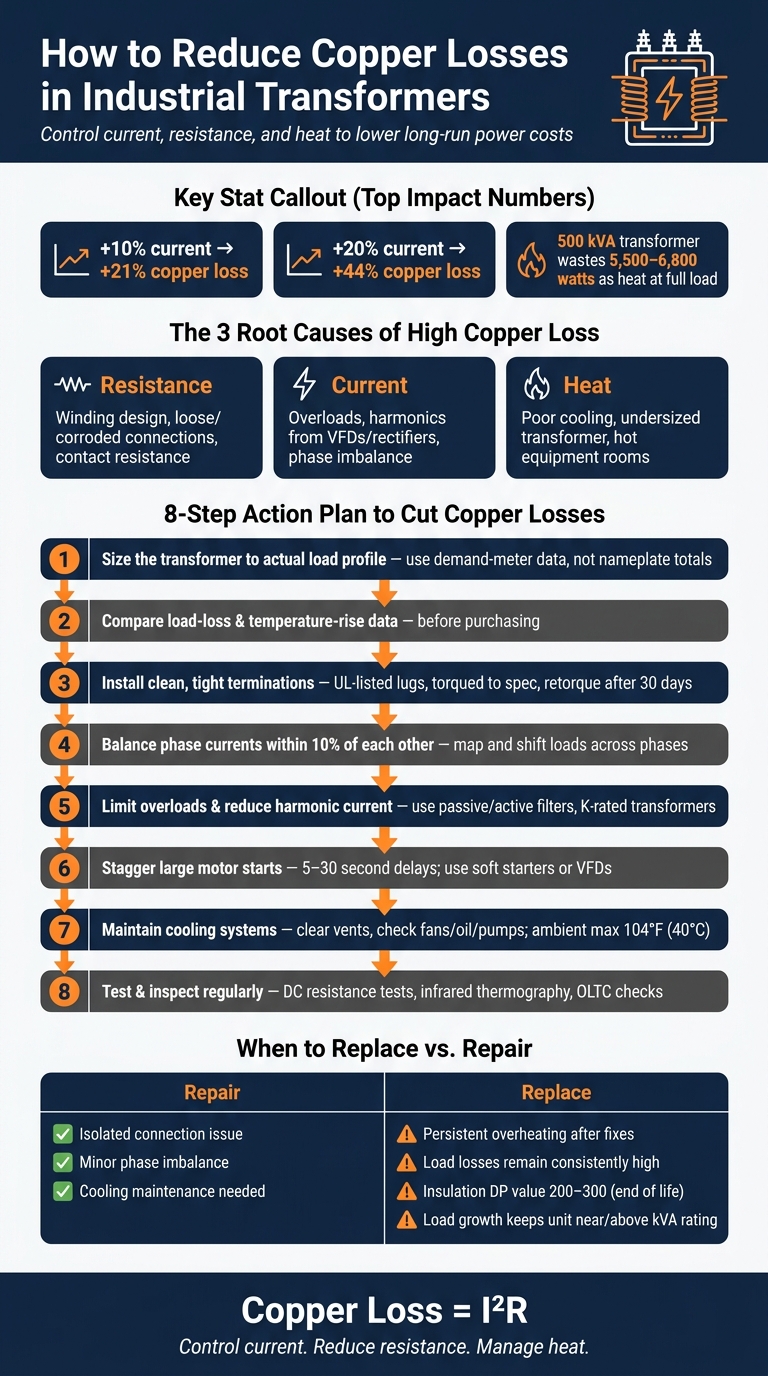
Copper loss can jump fast: a 10% current increase can push it up about 21%, and a 20% increase can push it up about 44%. If I want to cut waste in a plant transformer, I focus on five things first: right sizing, low-resistance connections, balanced phase loading, harmonic control, and cooling.
Here’s the short version:
- Copper loss follows I²R, so extra current hits hard.
- Loose or corroded connections add resistance and create hot spots.
- Harmonics from VFDs and rectifiers increase RMS current and add heat.
- Phase imbalance shifts too much current onto one phase.
- High temperature pushes winding resistance up, which means more loss.
- Testing and thermal scans help me catch trouble before repair costs climb.
A simple example shows why this matters: a 500 kVA three-phase liquid-filled transformer at full load may lose about 5,500 to 6,800 watts as heat. That turns into wasted energy, more cooling load, and added stress on insulation.
If I’m trying to reduce these losses, I keep the plan simple:
- Size the transformer to the actual load profile
- Compare load-loss and temperature-rise data before buying
- Install clean, tight terminations
- Keep phase currents within about 10% of each other
- Limit overloads and cut harmonic current
- Keep airflow, oil, fans, and vents in good shape
- Use DC resistance testing and infrared scans to track condition
- Replace the unit when heat, loss, and aging keep getting worse
Bottom line: if you control current, resistance, and heat, you cut copper losses and lower long-run power cost.
The rest of the article explains how I would do that in selection, installation, maintenance, and replacement decisions.
How to Reduce Copper Losses in Industrial Transformers
How Can Transformer Core And Copper Losses Be Reduced? - Electrical Engineering Essentials
sbb-itb-501186b
What Causes High Copper Losses in Industrial Service
Once a transformer is in service, copper loss usually climbs for three plain reasons: resistance, current, and heat.
Winding Resistance, Conductor Design, and Connection Resistance
Every transformer winding comes with built-in resistance. That starts with the design itself: the conductor material, the cross-sectional area, and the total winding length all shape how much resistance the winding has. If the winding is longer, resistance goes up, and so does heat at the same current.
In many plants, losses don't begin only inside the winding. They often show up at terminations, lugs, and bus connections. A loose bolt, a corroded lug, or a dirty contact surface adds extra resistance to the current path. And at high current, even a small jump in contact resistance can create severe local heating. Infrared scans often spot these hot areas before any visible damage shows up. If no one fixes them, the nearby insulation can carbonize. That pushes resistance even higher and speeds up the whole failure cycle.
Current is the next big part of the story.
Load Current, Harmonics, and Phase Imbalance
When a transformer runs near full load, copper losses climb fast. Push it into overload, and those losses jump even more.
VFDs, rectifiers, and other nonlinear loads make this worse. They distort current waveforms, which increases RMS current and, in turn, I²R loss. Harmonics also push AC resistance higher through skin effect.
Phase imbalance adds one more problem. In a three-phase system with balanced loading, copper loss spreads evenly across all phases. But when single-phase heaters, lighting circuits, or uneven motor feeds throw things off, one or two phases end up carrying more current than the others. That imbalance increases total I²R loss because the overloaded phases take the hit.
Then heat starts feeding the whole problem back into itself.
Heat Buildup and Poor Transformer Sizing
Winding resistance increases as temperature goes up. So when temperature rises, resistance rises too, and I²R loss climbs with it. This happens a lot when the transformer is undersized or its cooling is weak.
A transformer rated too close to peak demand will spend a lot of its service life running at high load factors. Non-sinusoidal loads also call for derating, which means the transformer's usable capacity drops when harmonics are present. Hot equipment rooms make cooling less effective, so winding temperatures rise faster even when the load stays the same.
How to Reduce Copper Losses When Selecting a Transformer
Procurement locks in a transformer's load-loss profile, thermal margin, and long-term operating cost before the unit ever gets to the plant. That matters because copper loss climbs with current, resistance, and heat. So the buying decision isn't just paperwork - it sets the rules for how the transformer will perform once it's in service.
Selection affects winding resistance, allowable current, and thermal headroom, which ties this section directly to the loss drivers covered earlier.
Match kVA Rating to the Actual Load Profile
One of the most common buying mistakes is sizing a transformer by adding up every motor and equipment nameplate. On paper, that can look safe. In practice, it often leads to oversizing, a higher upfront cost, and a unit that spends most of its life away from its best load point.
Use demand-meter data to see what the load actually looks like over time. Focus on peak kW and kVA, average loading, and seasonal swings. Size the transformer for the real duty cycle, not the nameplate total.
A few checks matter here:
- Include motor starting current for large motors
- Account for harmonic derating if VFDs or other nonlinear loads are present
- Add a realistic 5- to 10-year growth allowance
Compare Load-Loss, Efficiency, and Cooling Data
When you're comparing units, look past the purchase price. Review the published manufacturer data on load loss, no-load loss, efficiency at common load points, temperature rise, and cooling method. Those figures help you estimate what the transformer will cost to run, not just what it costs to buy.
In plants with high utilization, load loss deserves close attention because that's where copper losses show up under load. A transformer with lower load loss will often save more over its service life than a cheaper unit with weaker operating numbers.
Temperature rise matters too. If the transformer room runs hot or airflow is limited, a lower temperature-rise design can help. Better cooling holds winding resistance down and cuts I²R loss under load.
Use Electrical Trader to Compare Transformer Listings
Electrical Trader lets buyers filter transformer listings by kVA, voltage, and type, then compare load-loss and temperature-rise data side by side. That's useful when you're trying to balance operating cost against the upfront budget on new or used units.
After selection, installation and loading practices decide how much of that efficiency stays in place.
Installation and Operating Practices That Cut I²R Losses
Selection sets the baseline. After that, installation and day-to-day operation decide whether the transformer actually runs near that level. In plain terms: you can buy an efficient transformer and still lose the gain in the field.
Make Low-Resistance Connections and Balance Phase Loading
Driver: resistance
Use UL-listed lugs that match the conductor size, clean contact surfaces down to bare metal before assembly, and torque each connection to the manufacturer’s spec with a calibrated torque wrench. That sounds basic, but it matters. Loose joints create local I²R heating that often shows up during thermographic inspections, while overtightened connections can damage threads and deform lugs.
It also helps to retorque terminations after the first 30 days of service, once conductors have settled from thermal cycling.
Phase balance matters too. Keep phase currents within 10% of one another. A common fix is to map major loads by phase during a scheduled outage, then shift circuits in panels and MCCs to even out the draw. When crews do this and then run thermographic inspections again, they often see lower hotspot temperatures at points that were out of balance or poorly terminated before.
Once the connections are tight and the phases are balanced, the next thing to watch is excess current.
Control Overloads, Harmonics, and Excess Current
Driver: current
Cut sustained overloads, reduce harmonic current, and stagger large motor starts. Harmonic currents from variable frequency drives, rectifiers, and switched-mode power supplies increase RMS current even when the fundamental load seems fine. One modeled case found that reducing harmonics can cut distortion-related losses by up to 90% in heavily distorted circuits.
The most direct fix is usually harmonic filtering, whether passive or active. And if nonlinear loads are a permanent part of the load mix, K-rated transformers make sense to specify.
Large motor starts deserve their own attention. Stagger starts with PLC sequencing or start-delay procedures, using 5- to 30-second delays between starts. Soft starters and VFDs can cut inrush even more. These changes are often small - sometimes just a procedure update or a tweak in control logic - but they lower cumulative thermal stress over many start cycles.
Lower current helps, but final winding temperature still depends on how well the unit sheds heat.
Maintain Cooling Performance in Plant Conditions
Driver: heat
For dry-type units, keep vents and louvers clear, check fan rotation and airflow direction, and remove dust from enclosures on a regular basis. Indoor dry-type transformers may need about 100 ft³/min of airflow per kilowatt of transformer loss.
Standard transformer ratings assume an average ambient temperature of about 86°F (30°C), with a maximum of 104°F (40°C). If a plant room runs hotter than that - especially in summer - you may need to reduce load or add ventilation.
For oil-filled units, check oil level, confirm that pumps and fans are operating, and sample the oil from time to time for dielectric strength, moisture, and signs of oxidation or sludge. Temperature trending over time is one of the best early warning signs that cooling performance or load conditions have shifted in a way that is driving up copper losses.
Service Checks, Replacement Decisions, and Conclusion
Track Winding Condition with Testing and Thermal Inspection
Once a transformer is in service, testing tells you if your copper-loss control work is still doing its job.
DC winding resistance tests give you the clearest read on the current path through each winding. Compare each phase with the nameplate data or earlier test results, and look at phase-to-phase balance. If resistance climbs little by little, that often points to corrosion or degrading connections. If it jumps all at once, something likely changed recently, like a bad re-termination after repair. To spot trouble early, compare corrected readings with baseline values and watch for rising winding or joint resistance. Always correct readings to a standard reference temperature, such as 75 °C or 20 °C, before making comparisons.
Infrared thermography helps you find energized hot spots that resistance testing can miss. Scan terminals, bushings, and tap changer compartments under normal load. This is a good way to check whether a terminal, bushing, or tap changer is starting to show abnormal resistance. Log each image with the load level and date. That makes side-by-side review much easier during later inspections and helps you spot slow-moving issues before they turn into failures.
For on-load tap changers (OLTCs), annual visual checks of seals, heaters, and cabinets make sense as a starting point. Inspect contacts, seals, heaters, and lubrication on the schedule recommended for the unit. Worn contacts add resistance and create local heating, which is where small issues can snowball.
When to Replace or Upgrade a Transformer
At some point, repairs stop being the low-cost choice. When resistance, heat, or loading trends keep moving in the wrong direction, replacement or an upgrade starts to make more sense.
Replace or upgrade the transformer when overheating continues after corrective action, load losses remain high, or insulation aging is far along. Paper insulation with a degree of polymerization in the 200 to 300 range points to end-of-life conditions. Another clear trigger is load growth that keeps the unit running near or above its kVA rating. That kind of constant stress drives high I²R losses, adds heat, and cuts into remaining service life.
A lot of industrial sites don't go by age alone. They use a condition- and risk-based approach instead. That usually means looking at condition scores, DGA trends, thermal history, and how critical the transformer is to the operation. Life-cycle cost analysis can help you compare the cost of continued losses and repairs with the cost of installing a replacement.
If replacement is the right call, Electrical Trader is worth a look. The platform lists both new and used transformers across many kVA ratings and voltage classes, which helps when you're trying to match a unit to a specific load profile and budget. When you review listings, pay close attention to:
- Load-loss figures
- Cooling class
- Temperature rise rating
- For used units, available test reports and maintenance history
Conclusion: Key Steps to Reduce Copper Losses
Reducing copper losses comes down to a few core moves: proper sizing, low-resistance connections, harmonic control, solid cooling, and routine testing. Pick the right unit, install it carefully, track its condition, and replace it when the losses and repair costs no longer make sense.
FAQs
How do I know if my transformer is undersized?
Look for signs of electrical and thermal stress, like persistent overheating, nuisance tripping, or parts failing sooner than they should.
Then compare the actual load with the transformer’s kVA rating. If the transformer keeps running at a high percentage of its rated capacity, it may be undersized.
To verify that, use load monitoring or a high-precision power analyzer at the low-voltage terminals. That gives you a clear picture of demand, including the 125% margin for continuous loads.
When do harmonics become a serious loss problem?
Harmonics turn into a major loss issue when a transformer feeds nonlinear, harmonic-heavy loads such as VFDs or computers. The extra heat from those harmonics makes the transformer behave as if it’s carrying a much heavier load than the meter might suggest.
That’s why a standard transformer can hit thermal overload at only about 65%–70% of nameplate load in actual use. Inside the unit, losses can climb to around 95%–110% of full-load copper losses. And when harmonic distortion gets high, those losses can double or triple.
What tests best catch rising copper losses early?
Start with short-circuit (impedance) testing to measure copper losses directly. Then pair that with winding resistance checks. Why? Because copper losses go up as resistance rises, and they also increase with the square of the load current.
In day-to-day service, keep an eye on load so the transformer stays in its best operating range, about 40%–80%. If loading starts to climb, pay close attention. It also helps to check phase balancing and re-torque connections, since uneven currents or loose, oxidized joints can create hot spots and lead to local overheating.