How to Measure Core Loss in Transformers
Transformers always consume energy - even when not supplying power. This energy loss, called core loss, occurs due to heat dissipation in the magnetic core and is influenced by two primary factors: hysteresis loss and eddy current loss. Measuring core loss is vital for ensuring efficiency, detecting issues, and minimizing long-term costs. Here's how to measure it:
- Tools Needed: Use instruments like RMS voltmeters, wattmeters, and precision power analyzers for accuracy. For high-frequency applications, advanced tools are required.
- Setup: Apply rated sinusoidal voltage to the primary winding with the secondary winding open. Ensure proper grounding and calibration.
- Measurement Process: Record voltage, current, and waveform quality. Use IEEE guidelines to calculate losses and adjust for waveform distortions.
- Error Prevention: Address voltage/current measurement errors, phase/timing inaccuracies, and magnetic saturation for reliable results.
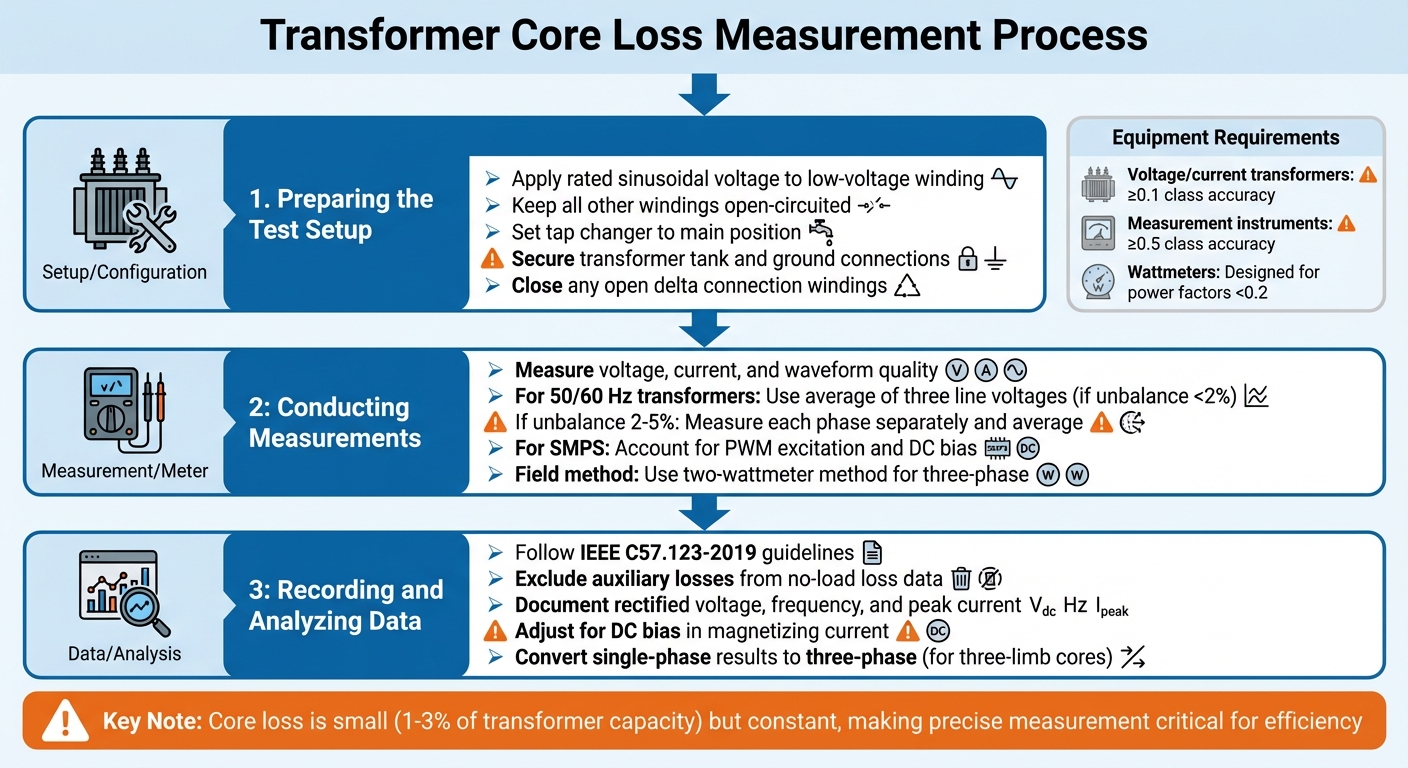
Core loss is small (1%-3% of transformer capacity) but constant, making precise measurement key to reducing energy waste and improving performance.
Transformer Testing | Core Loss and Excitation
sbb-itb-501186b
Tools and Equipment Needed
Getting precise measurements starts with having the right tools and setup. What you need depends on the transformer's size, operating frequency, and voltage level.
Measurement Instruments
For standard power and distribution transformers running at 50 or 60 Hz, specific meters are essential:
- Average-responding, RMS-calibrated voltmeter (Vₐ): This measures the average absolute value of the applied voltage, helping ensure the transformer reaches its rated voltage. Since peak flux density depends on the average voltage, this tool is key.
- True RMS voltmeter (Vᵣ): This captures the actual RMS voltage. The difference between Vₐ and Vᵣ highlights harmonic distortion, allowing you to adjust measured losses to a sine-wave basis.
- Wattmeter: This records the no-load power loss in watts.
For high voltages and currents, instrument transformers are used to scale down values, making them manageable for standard meters.
When dealing with high-frequency applications (10 kHz to 1 MHz) - like those involving ferrite cores or iron powder materials - you’ll need advanced tools such as precision power analyzers (e.g., ZES ZIMMER LMG series). These devices measure power, voltage, current, and magnetic properties in real-time. At these frequencies, even tiny delays can introduce errors; for example, a 3.8-nanosecond delay can cause a 2% error. Modern analyzers typically compensate for delays within 4 nanoseconds to maintain accuracy.
Temperature monitoring is also critical. Core loss increases by approximately 0.00065 p.u. for every 1°C drop in core temperature. For testing or research, environmental chambers that maintain controlled temperatures (from –20°C to +120°C) can be invaluable.
Once you’ve set up the instruments, proper calibration is a must to minimize measurement errors.
Calibration and Setup Tools
After choosing the right instruments, precise calibration ensures accurate results. A dual-voltmeter setup - combining an average-responding voltmeter and a true RMS voltmeter - helps correct waveform distortion. When the voltage waveform isn’t a pure sine wave, IEEE correction formulas can be applied for adjustments.
"The total error of the dissipation contains an amplitude error of the measured voltage and current and also a delay time difference error between these signals."
– ZES ZIMMER
To reduce delay and phase-shift errors, especially at high frequencies, use short, equal-length leads. Many modern power analyzers include internal delay adjustments to address these issues automatically.
For high-frequency testing, reference cores act as calibration standards. These known-value cores allow you to verify your setup’s accuracy before testing unknown transformers. If specific values for hysteresis and eddy-current losses aren’t available, IEEE suggests assigning each a value of 0.5 p.u. This simplifies calculations while maintaining reasonable accuracy.
These calibration methods play a crucial role in accurately assessing core loss, which is essential for efficient transformer performance.
Step-by-Step Measurement Process
Step-by-Step Process for Measuring Transformer Core Loss
After completing calibration, it's time to set up the transformer, measure its parameters, and carefully record the data.
Preparing the Test Setup
Start by applying a rated sinusoidal voltage to the low-voltage winding and keep all other windings open-circuited. For transformers with taps, ensure the tap changer is set to its main position before beginning. Confirm that the transformer tank and all ground connections are secure, and close any open delta connection windings before proceeding with measurements.
Use voltage and current transformers with at least 0.1 class accuracy, paired with measurement instruments offering no less than 0.5 class accuracy. Since no-load losses occur at very low power factors, choose wattmeters designed for power factors below 0.2.
Conducting Measurements
Once the setup is verified, measure the voltage, current, and waveform quality. For standard power transformers operating at 50 or 60 Hz, use the average of the three line voltages if the voltage unbalance is less than 2%. If the unbalance falls between 2% and 5%, measure each phase separately and average the results. When distortion is present, rely on the average voltage values to calculate no-load loss.
For switched-mode power supplies (SMPS), take into account the PWM excitation and any DC bias in the magnetizing current. As noted by Yongtao Han and Yan-Fei Liu in IEEE Transactions on Industrial Electronics:
"The core loss measurement schemes and related issues under sinusoidal excitations have been discussed a great deal... But not too much work has focused on the measurement scheme for transformer core loss in SMPS."
In field conditions, use the two-wattmeter method for three-phase power measurements. This approach involves two voltage and two current transformers. If the three-phase results indicate unexpectedly high losses, perform single-phase no-load tests to identify issues in specific magnetic circuits or core limbs.
These steps help maintain a consistent measurement process across various transformer types.
Recording and Analyzing Data
Once measurements are complete, document and analyze the data following the guidelines in IEEE C57.123-2019, which complement IEEE Std C57.12.90. Exclude auxiliary losses when recording no-load loss data to ensure the results reflect only core loss and excitation current.
Modern analyzers can compute rectified voltage, frequency, and peak current in real time, making it easier to perform detailed error analyses and reduce systematic errors . For magnetizing current data - especially in power converters - adjust for any DC bias to avoid calculation errors. Single-phase test results for transformers with a three-limb core can be converted to reflect three-phase performance. However, for five-limb cores, comparisons are only meaningful when tested against identical models.
Calculating Core Loss from Measurement Data
Flux Density and Core Loss Density
Getting accurate core loss calculations is key to improving transformer efficiency and managing energy costs. To convert your measurements into core loss data, you can rely on the Steinmetz Equation:
P₍ᵥ₎ = k · fᵃ · Bᵇ
Here’s what each variable represents:
- P₍ᵥ₎: Power loss per unit volume
- f: Operating frequency
- B: Peak magnetic flux density
- k, a, b: Material-specific constants
As explained by Wikipedia:
"Steinmetz's equation... is an empirical equation used to calculate the total power loss (core losses) per unit volume in magnetic materials when subjected to external sinusoidally varying magnetic flux."
To calculate the peak flux density (B₍ₚₖ₎), use the rectified secondary voltage instead of the RMS value. The formula is:
B₍ₚₖ₎ = U₍rect₎ / (4 · f · n₂ · A)
Where:
- U₍rect₎: Rectified voltage
- f: Frequency
- n₂: Secondary coil turns
- A: Effective cross-sectional area
For the peak magnetic field strength (H₍ₚₖ₎), calculate:
H₍ₚₖ₎ = (I₍ₚₖ₎ · n₁) / l₍magn₎
Here:
- I₍ₚₖ₎: Peak primary current
- n₁: Primary coil turns
- l₍magn₎: Magnetic path length
Using these values, you can find the relative permeability (μ₍a₎) with:
μ₍a₎ = B₍ₚₖ₎ / (μ₀ · H₍ₚₖ₎)
Material constants vary depending on the core type:
- Silicon steel: k ≈ 0.0001
- Amorphous metal: k ≈ 0.00001
- Ferrite: k ≈ 0.0005
The frequency exponent (a) typically ranges from 1.5 to 2.0, while the flux density exponent (b) is usually between 2.0 and 3.0. These constants are often provided by manufacturers or determined experimentally through curve-fitting techniques using B–H hysteresis loops.
Once you’ve calculated core loss density, it’s essential to adjust these results for real-world operating conditions.
Adjusting Results for Operating Conditions
Core loss values need to reflect actual operating environments. Temperature is a major factor: core loss increases by about 0.00036 per unit for every 1°F decrease in core temperature. Use a correction factor to account for differences between test conditions (e.g., 77°F) and operating conditions (e.g., 140°F). For high-frequency applications (10 kHz–1 MHz), perform measurements in controlled ambient temperatures between –4°F and 248°F to mimic real-world conditions.
Waveform distortion also impacts measurements. If the voltage waveform isn’t perfectly sinusoidal, adjust the measured power to a sine-wave equivalent using:
P₍c₎ = P₍m₎ / (P₁ + P₂ · (Vᵣ/Vₐ)²)
Where:
- P₍m₎: Measured power
- Vᵣ: True RMS voltage
- Vₐ: Average-responding voltmeter reading
If the hysteresis and eddy-current loss components are unknown, IEEE test codes suggest assuming each to be 0.5 per unit.
For non-sinusoidal waveforms, like rectangular waveforms common in modern power electronics, standard Steinmetz equations may not work well. Losses can occur even during zero-voltage periods due to magnetic relaxation. In these cases, advanced models like the improved-Generalized Steinmetz Equation (i²GSE) offer better accuracy.
Common Measurement Errors and Solutions
When performing precise measurements, it's essential to address common errors that can distort core loss calculations.
Voltage and Current Measurement Errors
Core loss testing is tricky because the losses are usually very small, and the phase shift between voltage and current is close to 90°. This results in a power factor (cos φ) that’s almost zero, meaning even minor errors can have a big impact. The magnetizing current and the core loss components, which are needed to generate flux, change the voltage-to-current relationship. Additionally, the secondary current often isn’t perfectly 180° out of phase with the primary current, leading to inaccuracies in power calculations at low power factors. As ZES ZIMMER puts it:
"The total error of the dissipation contains an amplitude error of the measured voltage and current and also a delay time difference error between these signals."
Another common issue is interference from winding (copper) losses. When measuring on the primary side, the resistance losses in the windings can mix with core losses. To avoid this, keep the secondary circuit open and measure the induced voltage instead.
Magnetic saturation is another factor that can skew results, as it distorts waveforms and often leads to underestimating the current. Additionally, DC bias in the magnetizing current can shift the operating point on the B-H curve, creating inaccuracies, especially in high-frequency converters.
To reduce these errors:
- Use short, equal-length measurement leads.
- Choose high-permeability core materials like Mumetal (76% Nickel), which can achieve a relative permeability of 90,000 at 0.35 Wb/m², compared to around 4,500 for standard silicon steel.
- Adjust the number of secondary winding turns (reduce by one or two) to align the actual transformation ratio more closely with the nominal value.
Beyond amplitude errors, phase and timing inaccuracies can further degrade measurement accuracy.
Phase and Timing Errors
At high frequencies, even a tiny delay - like 3.8 nanoseconds - can result in a 2% error, especially when the power factor is as low as 0.06. Unequal cable lengths can introduce signal delays between voltage and current channels, and these delays become more problematic as the power factor decreases.
To address this, use precision power analyzers that offer internal delay adjustments. These devices typically keep delay time differences under 4 nanoseconds. Additionally, use matched, short cables to minimize signal timing errors.
Conclusion
Summary of Measurement Steps
Measuring core loss accurately is key to improving transformer efficiency and cutting operational expenses. The Voltmeter-Ammeter-Wattmeter method is a reliable approach: apply excitation to the primary winding while leaving the secondary open to isolate core losses from copper losses. This method records three essential parameters: RMS voltage, RMS current, and the phase shift between them. Since core losses are associated with a phase shift close to 90°, leading to a very low power factor, even minor timing errors can skew results. To avoid this, use short, equal-length leads and precision power analyzers specifically calibrated for low power factor measurements.
Standards like IEEE C57.123 and ASTM A1013 provide guidance for these measurements. ASTM A1013, for instance, is tailored for high-frequency applications ranging from 10 kHz to 1 MHz. One standard emphasizes:
"The reproducibility and repeatability of this test method are such that it is suitable for design, specification acceptance, service evaluation, and research and development".
By following these methods, you'll not only achieve technical accuracy but also lay the groundwork for operational improvements.
Benefits of Accurate Core Loss Measurement
Precision in core loss measurement brings a host of benefits that highlight its importance. Accurate measurements enhance transformer efficiency and help lower long-term costs. By capturing ongoing no-load losses, they enable more precise lifetime cost estimations. For example, studies reveal that core loss increases by about 0.00065 per unit for every 1°C drop in core temperature.
Beyond financial benefits, precise measurements ensure compliance with design specifications and help identify potential issues - like localized insulation failures or loose core components - that might otherwise remain undetected. As noted by IEEE researchers:
"The accurate characterization of transformer losses, including core loss and copper loss, plays an important role in converter design and optimization".
This level of precision is especially critical for optimizing high-frequency switching mode power supplies and converter designs.
Whether you’re a utility company aiming to improve transmission efficiency, a manufacturer ensuring design compliance, or an engineer refining converter performance, consistent and accurate core loss measurement ensures transformers operate efficiently while minimizing energy waste and operational costs.
FAQs
How do I choose the right meter for low power factor core-loss tests?
When selecting a meter for core-loss testing, prioritize one designed to measure power accurately under low power factor conditions. Core-loss testing often involves scenarios with significant core losses, making precision crucial. Opt for instruments specifically calibrated for low voltage and current ranges, and ensure they meet IEEE standards. These standards recommend using wattmeters capable of handling power factors below 0.2 to deliver reliable and precise readings during such tests.
How can I tell if my voltage waveform distortion is skewing core-loss results?
Voltage waveform distortion can throw off core-loss calculations by affecting the precision of power measurements. When distortion leads to asymmetry or non-sinusoidal waveforms, it can introduce errors in loss estimates. To get reliable results, it's crucial to check that the waveform is as close to its ideal shape as possible before performing any measurements.
What’s the easiest way to separate core loss from winding (copper) loss?
The simplest method to differentiate between core loss and winding (copper) loss in a transformer involves conducting two key tests:
- No-load (open circuit) test: This test isolates core loss, as it primarily reflects the energy lost in the transformer's core.
- Short circuit test: This test focuses on winding (copper) loss, measuring the energy dissipated in the transformer windings.