Transformer TTR Test: Step-by-Step Guide
Transformers play a key role in electrical systems, and a Transformer Turns Ratio (TTR) test ensures they work properly. This test measures the ratio of turns between the primary and secondary windings, verifying that the transformer adjusts voltage as designed. Here’s what you need to know:
- Purpose: Confirms transformer performance matches its specifications. Detects problems like shorted turns, winding deformation, or insulation breakdown.
- Process: Apply a low-voltage AC signal to one winding, measure the induced voltage in the other, and compare the ratio to the nameplate values.
- Safety First: Always de-energize the transformer, follow Lockout/Tagout (LOTO) procedures, and use proper PPE.
- Tools Needed: A calibrated TTR tester, test leads, a digital multimeter, and cleaning materials.
- Results: The ratio should match the nameplate within ±0.5%. Deviations over 1% may indicate serious issues.
If the test identifies faults, immediate action can prevent equipment damage and costly downtime. Proper documentation ensures accurate tracking of transformer performance over time.
Performing a Transformer Turns Ratio (TTR) Test with the Raytech TR-Mark III
Safety Precautions and Equipment Preparation
When performing Transformer Turns Ratio (TTR) testing, prioritizing safety is non-negotiable. Working with transformer terminals can be hazardous, as they might have been exposed to high voltages. Even after shutdown, the risk of capacitive discharge remains. Proper safety measures are essential to protect both individuals and equipment.
Required Safety Measures
Before starting, ensure the transformer is fully de-energized and isolated from all loads, incoming cables, and outgoing circuits. Follow Lockout/Tagout (LOTO) procedures to eliminate the possibility of accidental re-energization. Once isolated, disconnect cables from the transformer’s bushing terminals and secure them with nylon rope to maintain adequate phase spacing clearance. Additionally, apply working grounds to all incoming and outgoing cables to prevent static buildup or accidental energization.
Use the appropriate Personal Protective Equipment (PPE), which includes insulated gloves, safety goggles or glasses, flame-resistant clothing, and safety footwear. As hvtestpro.com advises:
"Never bypass safety protocols. Always adhere to established safety guidelines to prevent accidents and ensure a secure testing environment".
Conduct testing in a well-ventilated area to manage heat dissipation, and ensure fire safety equipment, such as fire extinguishers, is close at hand. Before proceeding, inspect the transformer for visible damage, signs of overheating, or wear that could compromise safety or the accuracy of the test.
Once all safety protocols are confirmed, move on to preparing the necessary tools and equipment.
Tools and Equipment Checklist
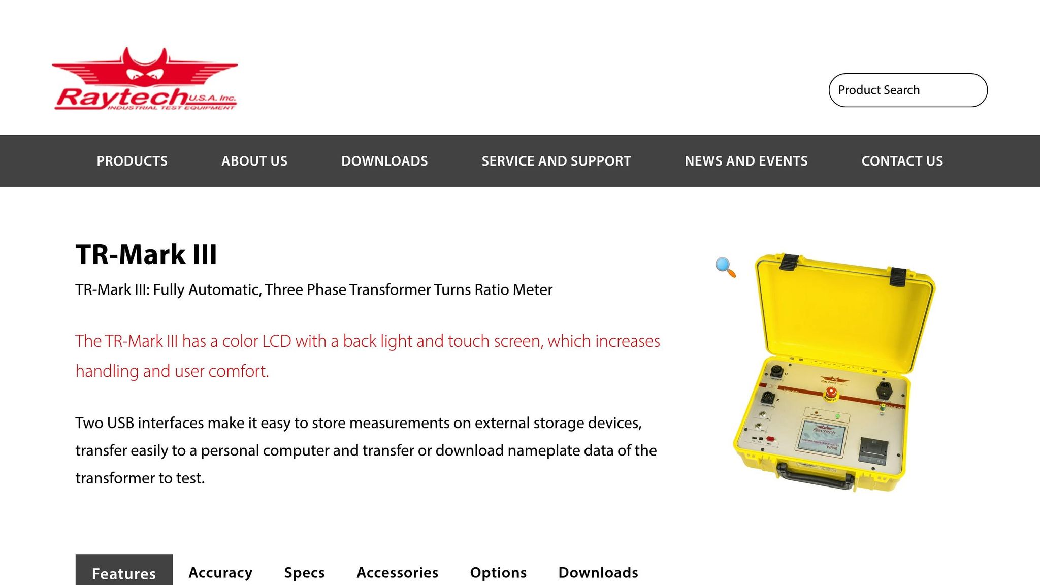
For accurate TTR testing, having the right tools in good condition is essential. The primary instrument is a Transformer Turns Ratio tester, such as the Megger TTRU3 or the handheld TTRU1, known for their high accuracy of ±0.05%. You'll also need H-designated test leads for high-voltage (primary) connections and X-designated test leads for low-voltage (secondary) connections. These leads often include military-style connectors with index notches to ensure correct alignment.
Additional tools include:
- A digital multimeter for initial continuity and voltage checks.
- Cleaning materials for bushing terminals to ensure clean and secure connections.
- Nylon rope to safely secure disconnected cables.
Before beginning, confirm that all instruments are properly calibrated. Clean the bushing terminals, check that connections are tight, and inspect test leads for any damage to reduce contact resistance and ensure reliable results.
Step-by-Step Guide to Performing a TTR Test
6-Step Transformer TTR Testing Process Guide
Once all safety precautions are in place and the equipment is ready, the TTR (Transformer Turns Ratio) test can begin. This process requires careful preparation, precise connections, systematic testing, and detailed documentation.
Preparing the Transformer for Testing
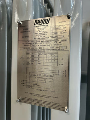
Start by identifying the high-voltage (H1, H2, H3) and low-voltage (X1, X2, X3; neutral as H0/X0) terminals. This step is crucial to avoid polarity errors. Double-check the markings on both the transformer and the test leads to ensure accuracy.
Make sure your TTR tester is properly calibrated, and clean all transformer bushings to guarantee low-resistance connections. Any dirt or buildup could interfere with accurate measurements. If the transformer is equipped with an on-load tap changer (OLTC), plan to test every tap position within its range.
Once the terminals are identified and the equipment is calibrated, you're ready to connect the test leads.
Connecting the TTR Tester
After identifying the terminals and calibrating the tester, attach the test leads to the TTR instrument, ensuring the index notches align correctly. Connect the H-designated leads to the high-voltage (primary) side and the X-designated leads to the low-voltage (secondary) side. Specifically, attach H1, H2, and H3 leads to their corresponding high-voltage bushings, and X1, X2, and X3 leads to the low-voltage bushings. If the transformer includes a neutral bushing and your test set supports it, connect the neutral lead as well.
For transformers with delta-configured low-voltage windings, it’s often better to use the step-up mode - applying voltage to the low-voltage side instead of the high-voltage side. This reduces errors caused by circulating currents. As Edvard Csanyi, an Electrical Engineer, explains:
"Any inequality in the magnetizing characteristics of the three phases will then result in a shift of the neutral and thereby cause unequal phase voltages."
Conducting the Test
The TTR tester uses a low-voltage AC signal applied to the primary winding and measures the induced voltage on the secondary winding. Modern testers also measure the turns ratio (TVR), excitation current, and phase deviation. For three-phase transformers, test each phase individually - or simultaneously if using a true three-phase tester. Be sure to test every tap position, allowing the tester to stabilize before recording measurements.
After completing the test, move on to documenting the results.
Recording Results
Document all readings immediately. Record the TVR, excitation current, and phase deviation for each phase and tap position. According to IEEE Std C57.152 (2013), the measured and calculated TVR values should match within ±0.5% of the nameplate specifications. Phase angle deviations should generally stay within ±0.2°, and excitation current readings should fall within ±10% of typical values. Additionally, note the ambient conditions and ensure all connections remain tight and secure throughout the test. These measurements are essential for identifying potential faults and defects.
| Step | Action | Key Detail |
|---|---|---|
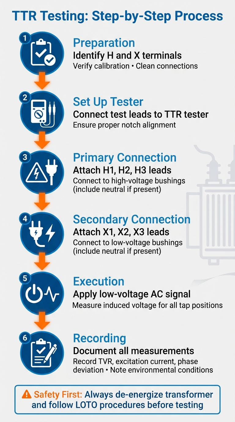
| 1 | Preparation | Identify H and X terminals; verify calibration; clean connections |
| 2 | Set Up Tester | Connect test leads to the TTR tester with proper notch alignment |
| 3 | Primary Connection | Attach H1, H2, H3 leads to high-voltage bushings (include neutral if present) |
| 4 | Secondary Connection | Attach X1, X2, X3 leads to low-voltage bushings (include neutral if present) |
| 5 | Execution | Apply low-voltage AC and measure induced voltage for all tap positions |
| 6 | Recording | Document TVR, excitation current, and phase deviation; note environmental conditions |
sbb-itb-501186b
Interpreting Test Results and Acceptance Criteria
Calculating the Turns Ratio
To determine the Transformer Voltage Ratio (TVR), divide the applied voltage by the induced voltage. Then, compare this result to the Transformer Nameplate Ratio (TNR), which is based on the line-to-line voltages listed on the transformer’s nameplate. For Delta-Wye configurations, make sure to apply a correction factor to account for the phase relationships.
Industry Standards and Tolerances
Once you've calculated the ratio, the next step is to evaluate it against established industry standards. The IEEE Std C57.152-2013 serves as the primary reference for acceptable deviations. According to this standard, the measured TVR should align with the nameplate ratio within a margin of ±0.5%.
In addition to the turns ratio, other key parameters also have defined tolerances. Excitation current should remain within ±10% of typical values, and phase angle deviation between phases must not exceed ±0.2°. A ratio deviation greater than 1% often points to serious issues, such as winding deformation. These tolerances apply across all tap positions since some faults only emerge at specific points on the tap changer. Therefore, it’s critical to test every tap position.
Identifying Faults and Defects
If deviations fall outside acceptable limits, specific patterns can help identify the root cause of transformer defects. For instance, unusual TTR results are often linked to particular problems. Shorted turns typically present as significant deviations from the nameplate ratio, accompanied by higher excitation current readings. If discrepancies are only observed at certain tap positions, the issue is likely tied to the tap changer mechanism - this could involve poor contacts or other performance issues.
Comparing phase results can also reveal localized issues with the windings or the core. As noted by Megger:
"The excitation current measurement can be used to detect problems in the magnetic core structure, winding defects, like shorted turns, and tap changer problems".
Megger further explains:
"Significant phase deviation therefore indicates an inefficient core",
which can suggest core material degradation or issues such as eddy currents.
For transformers with high ratios (greater than 20:1), consider modifying the test method to enhance accuracy. If results appear inconsistent, double-check the test lead connections to rule out setup errors.
These insights not only help pinpoint potential faults but also guide decisions on whether to repair or replace transformer components.
Post-Test Considerations and Recordkeeping
Documenting Test Results
Accurate documentation of test data is essential. Make sure to log the test date, transformer ID, test conditions, and all observed values for each tap position. This creates a reliable baseline for future comparisons and helps track the transformer's performance over time.
Keeping a historical record of measurements allows you to spot gradual degradation trends that might otherwise go unnoticed. Modern digital documentation tools make this process more efficient, enabling easier data analysis for informed maintenance decisions.
It’s also crucial to confirm that your testing instruments - such as ratio meters and multimeters - were calibrated according to the manufacturer’s specifications. Additionally, document that the transformer was de-energized and isolated using proper lockout/tagout (LOTO) procedures before testing began. This information is vital for evaluating performance under different environmental conditions.
Environmental Factors and Accuracy
Even though TTR measurements are performed under no-load conditions, environmental factors like temperature and humidity can still influence results. Be sure to record these conditions, as they can affect the electrical properties of the windings and core materials. Also, ensure that all connections are clean to maintain measurement accuracy.
If you notice inconsistencies in readings, consider increasing the excitation voltage or using a step-up method. Additionally, if a DC winding resistance test was conducted prior to the TTR test, demagnetize the core to eliminate any residual flux. These steps are critical for ensuring accurate results and guiding future maintenance actions.
When to Repair or Replace Transformers
Test results are key to determining whether maintenance or replacement is required. Immediate action is needed if ratio deviations exceed 1%, as this may indicate winding deformation. Similarly, excitation current variations greater than 10% from baseline values could signal core structure problems, shorted turns, or tap changer issues. A phase angle displacement greater than 0.2° between phases might suggest an inefficient core or inter-lamination defects. Uneven phase readings could point to localized winding or insulation faults.
If significant deviations are detected, inspect bushings and connections as part of your troubleshooting process. Results that exceed specified tolerances should prompt immediate repair or replacement. When documenting these decisions, include the specific measurements that led to the action and reference IEEE Std C57.152-2013 for compliance and future audits.
Conclusion
A TTR test is a quick and effective way to confirm a transformer's operational health. It helps uncover internal issues like shorted turns, winding deformation, and core irregularities - problems that, if ignored, could result in costly failures.
Safety comes first. Always ensure transformers are fully de-energized and isolated using proper Lockout/Tagout procedures before starting any tests. Modern automated testers have made strides in both speed and safety, operating 3 to 4 times faster than older hand-crank models while minimizing risks. These advancements not only improve safety but also enhance testing accuracy.
Accuracy hinges on proper calibration and clean connections, with modern TTR testers achieving precision levels of ±0.05%. To ensure consistent results, it’s crucial to document environmental factors like temperature and humidity, as well as maintain detailed records for tracking transformer performance over time. This meticulous approach ensures compliance with industry standards.
Industry guidelines specify that the turns ratio should stay within ±0.5% of the transformer's nameplate rating. Deviations exceeding 1% typically signal serious issues, such as winding deformation. By following strict safety measures, ensuring precise calibration, and keeping thorough documentation, you can enhance reliability and extend the lifespan of transformers.
For dependable testing equipment and high-quality replacement transformers, check out Electrical Trader (https://electricaltrader.com).
FAQs
What are the key indicators of transformer winding issues during a TTR test?
When performing a Transformer Turns Ratio (TTR) test, one of the main signs of winding problems is an unexpected change in the measured turns ratio. For instance, irregular readings can point to issues such as shorted turns, open circuits, or insulation failure.
These problems are usually detected by comparing the test results to the transformer's nameplate or design specifications. If there’s a noticeable difference, it could indicate winding deformation or other internal faults within the transformer.
How do environmental factors impact Transformer Turns Ratio (TTR) test results?
Environmental conditions play a crucial role in the accuracy of Transformer Turns Ratio (TTR) test results. Factors like temperature, humidity, and electromagnetic interference can all affect the readings, sometimes leading to misleading conclusions.
For instance, temperature changes can alter the electrical properties of transformer windings and insulation, which may result in fluctuating ratio readings. Similarly, high levels of humidity can allow moisture to seep into the insulation, disrupting its dielectric properties and skewing the measurements. On top of that, electromagnetic interference from nearby machinery or equipment can introduce noise into the test signals, making it harder to interpret the data accurately.
To achieve reliable TTR results, it’s essential to conduct tests in a controlled setting. Maintaining stable environmental conditions and minimizing external disruptions can significantly reduce the chances of inaccurate readings.
How do I know if a transformer needs repair or replacement based on TTR test results?
If the Transformer Turns Ratio (TTR) test reveals a deviation exceeding ±0.5% from the nameplate ratio, it might be a sign that the transformer requires repair or replacement. Such a deviation could point to issues like damaged windings, core defects, or other internal faults.
Consistent testing and addressing abnormal results quickly can help avoid additional damage and maintain safe, efficient operation.