Hazardous Locations: Safe and Non-Safe System Setup
Working in hazardous locations requires strict adherence to safety protocols. Here's what you need to know:
- Hazardous areas are classified based on materials (gases, dust, fibers), frequency of hazards (normal vs. abnormal conditions), and material groups (specific chemical properties).
- Safe system setups aim to prevent explosions by breaking the "ignition triangle" (fuel, oxygen, ignition source).
- Two main protection systems are used:
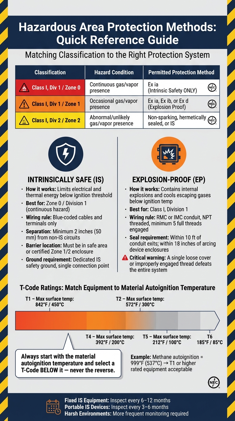
- Intrinsically Safe (IS): Limits electrical/thermal energy to prevent ignition.
- Explosion-Proof: Contains internal explosions and prevents external ignition.
- Proper classification (Class, Division/Zone, Group) is critical for selecting compliant equipment and ensuring safety.
- Key safety practices include:
- Clear separation of IS and non-IS circuits.
- Using approved equipment with correct T-code ratings.
- Grounding and bonding to prevent static sparks.
- Routine inspections and audits to maintain compliance.
Bottom line: Safety in hazardous locations is about precision, compliance, and regular maintenance. Missteps can lead to severe risks, so every detail matters.
Checklist for Safe and Non-Safe System Boundaries
Defining Safe and Non-Safe Zones
To establish safe and non-safe zones, confirm the Class, Division, and Group of each area to determine the appropriate protection methods.
| Classification | Hazard Condition | Permitted Protection Method |
|---|---|---|
| Class I, Div 1 / Zone 0 | Continuous gas/vapor presence | Ex ia (Intrinsic Safety only) |
| Class I, Div 1 / Zone 1 | Occasional gas/vapor presence | Ex ia, Ex ib, or Ex d (Explosion Proof) |
| Class I, Div 2 / Zone 2 | Abnormal/unlikely gas/vapor presence | Non-sparking, hermetically sealed, or IS |
Clearly mark the boundary between hazardous and safe areas, and install barriers or isolators at these points. One critical rule to follow: Intrinsic Safety (IS) barriers must always be located in the safe area or, at the very least, inside a certified Zone 1 or Zone 2 enclosure. These barriers should never be placed inside a Zone 0 environment.
"The intrinsic safety concept applies to the whole system and not to any one item only." - EICS Tech
Once the boundaries are defined, ensure that wiring practices respect and maintain the separation between safe and hazardous zones.
Separation of Circuits and Wiring
Maintaining clear separation between circuits is essential for safety. IS circuits and non-IS circuits must be kept apart, as specified by NEC Article 504. For example:
- IS conductors cannot share the same raceway, cable tray, or cable with non-IS conductors.
- When IS wiring is run outside a raceway, maintain a minimum separation of 2 inches (50 mm) and secure both types of wiring to prevent accidental contact.
Inside enclosures and junction boxes, take steps to prevent any interaction between IS and non-IS systems:
- Use dedicated terminal blocks for IS circuits - never share a terminal strip with AC-powered equipment.
- Secure wiring to avoid contact with non-IS terminals.
- Use blue-colored cabling and terminals exclusively for IS circuits, as required under NEC 504.80(C).
Electrical consultant Mark Lamendola emphasizes:
"The control drawing is the master plan for everything in an IS system."
The control drawing, mandated by NEC 504.10(A), outlines the exact wiring methods, maximum cable lengths, and grounding requirements for your specific IS system. Following this drawing is not just recommended - it’s a legal requirement under U.S. code. Additionally, label all IS raceways and wiring every 25 feet with the phrase "Intrinsic Safety Wiring".
sbb-itb-501186b
Understanding Intrinsically Safe Systems per the NEC
Hazardous Area Classification and Equipment Selection
Hazardous Location Protection Methods: IS vs. Explosion-Proof Quick Reference
Verifying Area Class, Division, and Group
Before choosing equipment, it's essential to confirm the area's Class, Division/Zone, and Group. These classifications define the type of hazard present:
- Class I: Flammable gases and vapors
- Class II: Combustible dusts
- Class III: Ignitable fibers
Pay special attention to low-lying spaces like pits, trenches, and sumps. These areas can become Division 1 hazards since heavier-than-air vapors - such as propane or butane - tend to collect there, even if the surrounding floor-level areas are classified as Division 2. Treat each area individually instead of assuming the same classification applies to the entire building.
Ventilation plays a big role here. Proper ventilation can shrink the size of a classified area or even downgrade a Division 1 space to Division 2. If there’s any change to equipment, piping, or ventilation systems, it’s mandatory to review area classification drawings right away under Management of Change (MOC) protocols.
"Area classification does not eliminate the presence of flammable gases; rather, it ensures that electrical installations in each zone or division are designed to contain or prevent ignition." - API RP 505 Engineering Guide
Another critical step is identifying the autoignition temperature of the materials in the area. For example, methane (natural gas) has an autoignition temperature of 999°F (537°C). Materials with lower autoignition temperatures require stricter T-Code ratings for equipment. Always base your equipment selection on these ratings.
Once the classification is confirmed, ensure that all installed devices meet the necessary safety standards.
Selecting Approved Equipment
The next step is matching equipment to the area's classification. Start by checking the nameplate details for Class, Division/Zone, Material Group, and T-Code. Any equipment used in classified locations must carry certification from a Nationally Recognized Testing Laboratory (NRTL) such as UL (Underwriters Laboratories) or FM (Factory Mutual). A manufacturer's claim isn’t enough - inspectors rely on the NRTL marking on the nameplate.
"Equipment shall be approved not only for the class of location, but also for the ignitable or combustible properties of the specific gas, vapor, dust, or fiber that will be present." - Occupational Safety and Health Administration
The protection method must also align with the classification. Here’s a quick breakdown of common methods and their uses:
| Protection Method | Applicable Location | How It Works |
|---|---|---|
| Explosion Proof | Class I, Div 1 | Contains explosions and cools escaping gases |
| Intrinsically Safe | Zone 0 / Div 1 | Limits electrical and thermal energy |
| Purged/Pressurized | Zone 1 & 2 / Div 1 & 2 | Maintains positive pressure to exclude hazards |
| Dusttight | Class II, Div 2 | Prevents dust entry under specific conditions |
For intrinsically safe systems, equipment selection goes beyond the nameplate. You’ll need to perform Entity Parameter Matching, which ensures the barrier’s output parameters (Voc, Isc) are compatible with the field device’s input ratings (Vmax, Imax).
"The 'Entity Concept' is a set of calculations to prove that the barrier, field device, and cable are all compatible and the entire loop is safe." - Intrinsically Safe Store
Temperature ratings are another critical factor. As Randy Barnett, an electrical code and safety expert, explains:
"The operating temperature of electrical equipment must not exceed the autoignition temperature of gases or vapors."
For example, a T4-rated device has a maximum surface temperature of 275°F (135°C). If your area contains a gas with an autoignition temperature below that, you’ll need a device rated T5 (212°F / 100°C) or T6 (185°F / 85°C). Always start with the material’s autoignition temperature and work downward to find the right T-Code - never the other way around.
Installation Checks for Wiring, Grounding, and Bonding
Conduit and Cable Routing
Once the boundaries between safe and hazardous systems are clearly defined, it's time to focus on conduit and cable routing. In Class I, Division 1 locations, it's critical to use RMC (Rigid Metal Conduit) or IMC (Intermediate Metal Conduit) that is threaded to National Standard Pipe Taper (NPT). Ensure at least five full threads are engaged to create a secure flame path.
"Every connection must be wrench-tight with at least five full threads engaged, creating a flame path that cools escaping gases below their ignition temperature." - Delta Wye Electric
Boundary seals should be installed within 10 feet of conduit exits, and enclosure seals must be placed within 18 inches of enclosures containing arcing devices in Division 1 areas. When sealing, pour the sealing compound to fully encase the conductors, ensuring the fitting is filled to at least the conduit trade size (minimum 5/8 inch). Additionally, conduit exits should be sealed and pitched to drain away from equipment, which helps prevent moisture buildup.
For intrinsically safe (IS) and non-IS wiring, maintain a 2-inch separation or use a grounded partition to keep them apart. IS wiring must also be labeled every 25 feet with "Intrinsic Safety Wiring" or identified using blue coding. For example, during a refinery upgrade, Delta Wye Electric replaced 47 explosion-proof temperature transmitters with IS models. This switch allowed the use of simple twisted-pair wiring instead of costly explosion-proof conduit, cutting installation costs by 60%.
Once conduit routing and labeling are complete, the next step is to confirm that grounding and bonding meet the necessary safety standards.
Grounding and Bonding Requirements
With conduit routing verified, grounding and bonding play a crucial role in ensuring safety. Bonding equalizes the electrical potential between conductive parts, preventing static sparks, while grounding provides a direct path to earth for fault currents. Both are critical in Class I, Division 1 locations, as outlined in NEC 501.30.
Grounding for intrinsically safe systems is even more demanding. Zener barriers require a dedicated IS safety ground that is isolated from the general equipment ground. This safety ground should connect to the facility ground at only one point to avoid ground loops. On the other hand, galvanic isolators don’t need a separate safety ground because they use transformers or optical isolators to break the electrical connection.
When testing bonding continuity, use a low-resistance ohmmeter. The resistance between bonded surfaces should be less than 25 Ω, though many critical applications aim for 5 Ω or less. For static bonding cables, copper conductors with a minimum size of 2 AWG and spring-loaded clamps rated for at least 100A are recommended. Always follow the manufacturer’s control drawing for grounding - it’s a non-negotiable NEC requirement.
"If the cable entry are wrong or the earthing is done wrong, even a completely approved transmitter can become dangerous." - Sundareswaran Iyalunaidu, AutomationForum.Co
Final Inspection and Compliance Review
Documentation and Labeling Review
Once the wiring, grounding, and bonding checks are complete, the focus shifts to paperwork and physical labeling during the final inspection. Surprisingly, delays often result from missing or unclear documentation rather than complicated code issues. Hui LIU of TPS Electric explains:
"Most inspection delays are not 'mystery code problems.' They're missing documentation, unclear equipment identification, or markings that don't match the as-built cabinet."
Key documents required include one-line diagrams, as-built Bills of Materials (BOM), protective device datasheets, manufacturer installation instructions, and Intrinsically Safe (IS) control drawings. Redlined as-built drawings, inspection logs, and test results are also essential. For IS systems, having the manufacturer-supplied control drawing on hand is not just helpful - it’s a legal obligation under U.S. code. Any field modifications must be captured in redlined drawings and reflected in updated labels.
During the inspection, ensure that equipment nameplates display the correct NRTL (Nationally Recognized Testing Laboratory) mark, such as UL or FM, and confirm that certifications align with the installed configuration - not just the classification details verified earlier. Disconnects must be labeled clearly to indicate both the load they serve ("Disconnect for [Equipment]") and their power source ("Fed from [Panel/Feeder]"). Circuit directories should be permanent and precise - entries like "spare" are unacceptable. A good test for labeling effectiveness is to have someone unfamiliar with the system use the labels to identify equipment, its power source, and how to shut it off. If they struggle, the labels need improvement.
| Documentation Category | Required Items |
|---|---|
| Design & Power | One-line diagrams, power distribution layouts, earthing/bonding diagrams |
| Component Data | As-built BOM, protective device datasheets, NRTL certification documents |
| Installation Guidance | Manufacturer installation instructions, mandatory IS control drawings |
| Field Records | Redlined as-built drawings, inspection logs, continuity and insulation test results |
Thorough documentation not only streamlines inspections but also ensures on-site system verification is accurate and efficient.
Field Verification and System Auditing
After documentation and labeling are reviewed, the next step is a detailed field audit. This ensures that the installed systems match approved designs. For IS systems, compliance involves mathematical verification using the Entity Concept. This means confirming that the sum of instrument capacitance (Ci) and cable capacitance (Ccable) does not exceed the barrier's maximum external capacitance (Ca). The same principle applies to inductance. If wiring or entity parameters don’t comply, the entire circuit’s intrinsic safety is compromised.
For explosion-proof (EP) systems, attention to detail is critical. Inspect enclosure bolts, conduit threads, and Chico seals to confirm they are properly engaged and intact. As Industrial Monitor Direct warns:
"a single loose cover or improperly engaged conduit thread can defeat the entire EP system".
Unused enclosure entries must be sealed with certified stopping plugs. Improvised or temporary seals are not acceptable.
| Audit Category | Specific Verification Steps |
|---|---|
| Markings & Labels | Verify NRTL markings, Gas Group (A–D or IIC/IIB/IIA), and T-code (T1–T6) |
| Wiring & Glands | Confirm cable glands match cable construction; check for certified stopping plugs on unused entries |
| IS Loop Safety | Ensure (Ci + Ccable) ≤ Ca and (Li + Lcable) ≤ La according to barrier specs |
| Visual Integrity | Check for cracks, corrosion, missing seals, and ensure safety labels are visible |
Routine audits, conducted every 6–12 months, are considered best practice in the industry. These inspections help identify wear, corrosion, or unauthorized modifications to IS barriers and equipment before they escalate into safety issues. Personnel performing these audits must have documented training in explosion protection techniques, as required by IEC 60079-14. Competency in this area is not optional - it’s essential for maintaining compliance and safety.
Conclusion
Every step in the checklist plays a critical role in preventing disastrous failures. From classifying hazardous areas to verifying parameters and maintaining detailed documentation, each action ensures safety and compliance. When working in hazardous locations, there's no room for "close enough" - precision is non-negotiable.
Electrical consultant Mark Lamendola emphasizes this point: "The control drawing is the master plan for everything in an IS system." Straying from the design - no matter how well components seem to fit - can undermine intrinsic safety and create serious hazards.
Key practices like physical separation, proper grounding, certified seals, and accurate labeling aren't just about meeting standards - they actively reduce ignition risks. As Industrial Monitor Direct explains, when maintenance teams understand that these systems protect lives, "they are far less likely to take shortcuts that compromise system integrity."
Routine audits are also essential. For fixed IS equipment, inspections every 6–12 months are recommended, while portable devices may require checks every 3–6 months. Equipment in harsh environments often needs even closer monitoring to catch issues like wear, corrosion, or unauthorized modifications before they escalate.
For projects that demand certified components and strict adherence to safety standards, Electrical Trader offers a wide range of approved equipment. Whether you need IS barriers, explosion-proof enclosures, or power distribution systems, their inventory supports safe and compliant installations.
FAQs
When should I choose intrinsically safe (IS) vs. explosion-proof protection?
For low-power devices such as sensors, thermocouples, and gas detectors, intrinsically safe (IS) systems are the go-to option. These systems work by limiting the energy within the device, ensuring it can't ignite hazardous materials. This makes them ideal for Zone 0 environments, where explosive gases are always present. Plus, IS systems allow for live maintenance without requiring a gas-free workspace.
For high-power equipment like motors and transformers, explosion-proof (EP) systems are the better choice. These systems use rugged enclosures designed to contain any internal explosions, preventing them from spreading to the surrounding environment. However, they come with trade-offs - they tend to be heavier, bulkier, and more expensive to install.
Where can IS barriers or isolators be installed in a hazardous location?
IS barriers and isolators are typically placed in nonhazardous areas to ensure safe connections between control systems and field devices operating in hazardous zones. However, they can also be installed directly in hazardous environments, but only if they are explicitly certified for those conditions. If the equipment isn’t rated for the hazardous location, additional protective measures must be implemented to comply with the National Electrical Code requirements.
What’s the fastest way to verify an IS loop is compliant (entity parameters)?
To ensure an intrinsically safe loop complies using the entity concept, verify that the maximum input values of the field device (Ui, Ii, Pi) are equal to or greater than the maximum output values of the associated apparatus (Uo, Io, Po). Additionally, check that the combined capacitance (Ci + Ccable) and inductance (Li + Lcable) remain within the apparatus's defined limits (Ca and La).