How Intrinsically Safe Equipment Works in Gas Zones
Intrinsically safe equipment prevents explosions in hazardous gas environments by limiting electrical and thermal energy to levels that cannot ignite flammable gases or vapors. This safety approach is essential for industries like refineries, chemical plants, and mining, where explosive atmospheres are common. Unlike explosion-proof systems that contain blasts, intrinsically safe systems focus on preventing ignition altogether.
Key points to know:
- How it works: Intrinsically safe designs operate at low power (typically under 29V and 300mA) and use components like resistors, Zener diodes, and safety barriers to control energy levels, even during faults.
- Applications: Ideal for low-power devices (e.g., sensors, handheld tools) in high-risk areas, including Zone 0 (continuous explosive atmospheres).
- Advantages: Enables live maintenance, reduces installation costs (no heavy enclosures needed), and supports portable devices like smartphones.
-
Gas Zones: Classified by risk levels:
- Zone 0: Continuous presence of explosive gases.
- Zone 1: Likely presence during normal operations.
- Zone 2: Rare, only during abnormal conditions.
- Certification: Equipment must meet strict standards (e.g., ATEX in Europe, UL/FM in the U.S.) and be tested as part of a complete system.
This method is the only approved solution for the most hazardous areas, offering a safer, cost-effective alternative for managing risks in explosive environments.
Intrinsically Safe Equipment vs. Explosion-Proof Enclosures
sbb-itb-501186b
How Intrinsic Safety Works
Intrinsic safety is all about preventing ignition by keeping electrical and thermal energy levels below what’s needed to spark an explosion - even in the event of equipment faults. This principle directly targets the ignition source in the combustion triangle (which also includes fuel and an oxidizer), ensuring no spark or heat can trigger a dangerous reaction.
Roger Highton, MTL Product Line Manager for intrinsic safety at Eaton, explains it well:
"Intrinsic safety (IS) is an electrical design approach that prevents explosions from occurring by ensuring that the energy transferred to a hazardous area is well below the energy required to initiate an explosion."
The design must remain safe even during faults like short circuits or component failures. For highly hazardous environments, such as Zone 0 areas where explosive gases are consistently present, "ia" level protection incorporates a 1.5 safety factor and accounts for two simultaneous faults.
Typically, intrinsically safe equipment operates at less than 29 V and 300 mA. Devices like switches or thermocouples that generate no more than 1.5 V, 0.1 A, or 25 mW don’t even require certification. This low-power approach makes intrinsic safety ideal for sensors, handheld devices, and communication tools. However, it’s not suitable for high-power equipment, like motors or large lighting systems.
Energy Limitation Methods
Intrinsic safety relies on several techniques to keep energy levels in check. For instance:
- Series resistors are designed to fail open, cutting off power before it reaches dangerous levels.
- Zener diodes, placed in parallel, cap voltage and safely redirect excess energy to the ground.
- Capacitors and inductors - which can store energy - are carefully managed. Resistors are added to slow capacitor discharge, while inductive circuits (like relay coils) use parallel diodes to absorb energy spikes when circuits are interrupted.
Another key element is the use of safety barriers, which isolate hazardous areas from safe zones. For example, a Zener barrier uses a resistor and Zener diode circuit to redirect fault voltages (over 250 V) to the ground until a fuse blows, protecting the hazardous zone. Galvanic isolators, on the other hand, physically separate input and output circuits, avoiding grounding issues altogether.
Even passive components like cables require attention. Over long distances (typically beyond 400 meters), their capacitance and inductance can store hazardous energy, so system parameters must be carefully managed. Additionally, temperature control is critical - components must stay below the auto-ignition temperature of surrounding gases, even during internal faults, to avoid generating excessive heat.
These measures collectively ensure compliance with regulatory standards, which will be explored further in upcoming sections.
Intrinsic Safety vs. Other Protection Methods
Intrinsic safety stands apart from other protection techniques, such as explosion-proof or segregation methods. Explosion-proof systems (Ex d) are built to contain internal explosions within sturdy enclosures, while segregation methods physically separate fuel from ignition sources.
| Feature | Intrinsic Safety (Ex i) | Explosion-Proof (Ex d) |
|---|---|---|
| Primary Principle | Prevents ignition from occurring | Contains an internal explosion |
| Energy Level | Limited voltage and current | Allows higher power levels |
| Installation | Lightweight; uses standard instrumentation cables | Involves heavy, expensive enclosures and conduits |
| Application | Sensors, smartphones, low-power instrumentation | Motors, compressors, high-power lighting |
One major advantage of intrinsic safety is that it allows "live working." Technicians can service equipment in hazardous areas without shutting down operations or waiting for gas clearance. Plus, installation is simpler and more affordable. Lightweight, standard cables replace the heavy conduits and enclosures required by explosion-proof systems, making intrinsic safety a flexible and cost-effective choice for low-power applications in gas-specific environments.
Gas Zone Classifications and Requirements
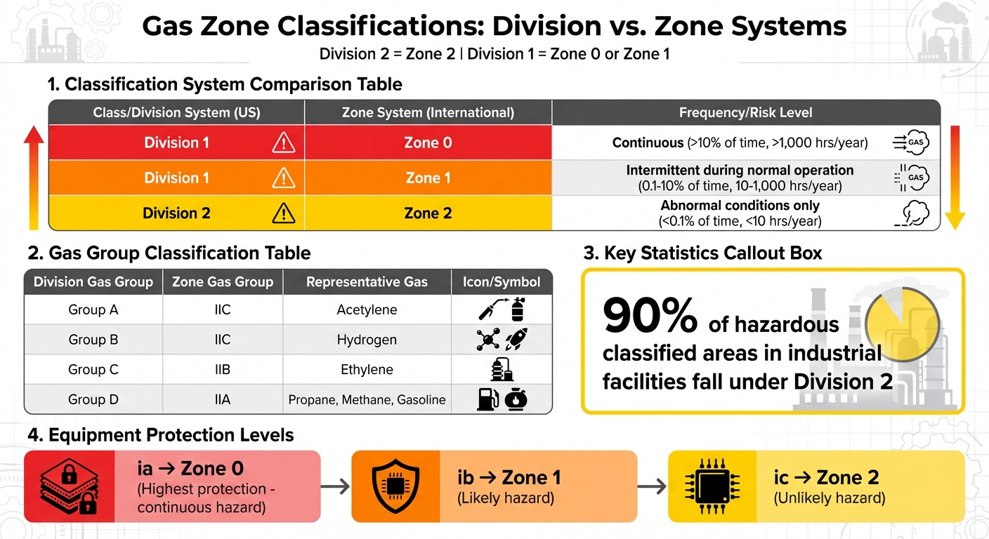
Gas Zone Classifications: Division vs Zone System Comparison Chart
Understanding hazardous area classifications is essential when selecting intrinsically safe equipment. In the United States, two systems define areas where explosive gas atmospheres might occur: the Class/Division system (outlined in NEC Article 500) and the Zone system (aligned with international IEC standards and covered under NEC Article 505).
Class/Division System in the US
The Class/Division system has been the standard in North America for years. Class I locations refer to areas where flammable gases, vapors, or mists are present - or could be - in amounts capable of creating explosive mixtures. These locations are further divided into two categories:
- Division 1: Areas where ignitable concentrations of hazardous substances exist under normal operating conditions.
- Division 2: Areas where hazardous concentrations are present only under abnormal conditions, like equipment failures or leaks.
Gases are grouped into Groups A through D based on their ignition properties, with equipment needing to comply with specific Temperature Codes (T-Codes). These codes range from T1 (≤842°F) to T6 (≤185°F), ensuring that equipment surface temperatures stay below the auto-ignition point of the gases present. For example, Group A includes acetylene, Group B covers hydrogen, Group C includes ethylene, and Group D encompasses gases like propane, methane, and gasoline vapors.
Paul Babiarz, Manager of Business Development at Cooper Crouse-Hinds, highlights that 90% of hazardous classified areas in industrial facilities fall under Division 2.
Zone System and International Standards
The Zone system, detailed in NEC Article 505, aligns with IEC/EN 60079-10 standards and offers a more detailed risk assessment with three levels:
- Zone 0: The highest risk, where explosive atmospheres are present continuously or for over 1,000 hours per year (more than 10% of the time). An example would be the interior of a vented fuel tank.
- Zone 1: Areas where explosive atmospheres are likely during normal operations, typically between 10 and 1,000 hours per year (0.1% to 10% of the time).
- Zone 2: Locations where hazardous conditions occur briefly during abnormal situations, usually for less than 10 hours annually (under 0.1% of the time).
Paul Babiarz explains, "Division 2 is equivalent to Zone 2, while Division 1 is either Zone 0 or Zone 1". Zone 0 demands the highest level of protection, such as intrinsic safety (type "ia"). Edward M. Briesch adds in IAEI Magazine, "In a Zone 0 location, intrinsically safe apparatus and the associated intrinsically safe circuit are the only wiring methods and protection technique that are permitted to be installed".
| Class/Division System | Zone System | Frequency |
|---|---|---|
| Division 1 | Zone 0 | Continuous (>10% of time) |
| Division 1 | Zone 1 | Intermittent (normal operation) |
| Division 2 | Zone 2 | Abnormal conditions only |
| Division Gas Group | Zone Gas Group | Representative Gas |
|---|---|---|
| Group A | IIC | Acetylene |
| Group B | IIC | Hydrogen |
| Group C | IIB | Ethylene |
| Group D | IIA | Propane, Methane, Gasoline |
Equipment designed for the US Zone system is marked with the "AEx" symbol, signifying compliance with American standards (ISA/UL). Internationally, the "Ex" symbol is used for IEC standards. NEC 501.1 allows zone-rated equipment in Class I, Division 2 areas, as long as it matches the gas group and temperature class requirements. Furthermore, the NEC mandates that area classification and equipment selection for Zone systems must be supervised by a qualified Registered Professional Engineer (PE).
A notable difference between the systems involves electrical terminations. Babiarz notes, "Under the zone concept, wire terminations are not considered an ignition source if they are rated as increased safety". This permits non-metallic enclosures in Zone 1 applications, whereas Division 1 typically requires metallic explosion-proof enclosures due to the assumption that wire terminations could act as ignition sources.
These classification systems are critical for shaping the design and certification standards needed for intrinsically safe equipment in hazardous gas zones. They lay the foundation for compliance and safety evaluations.
Certification and Compliance Standards
Once hazardous areas are classified, strict certification processes ensure that intrinsically safe equipment performs reliably, even in challenging environments.
Intrinsically safe equipment doesn’t just get a “safe” label from the manufacturer. It must undergo extensive third-party testing and certification to confirm it won’t ignite explosive atmospheres. In the United States, this means approval from a Nationally Recognized Testing Laboratory (NRTL) like Underwriters Laboratories (UL) or FM Global. In Europe, ATEX certification is legally required under Directive 2014/34/EU.
This safety standard applies to the entire system - devices, barriers, and cables must all be certified together. This end-to-end certification ensures that every component works safely as part of the whole system, reinforcing the safety principles discussed earlier.
Certification Bodies and Standards
Different regions have their own certification bodies and standards for intrinsically safe equipment. In the U.S., UL and FM Global test against NEC 500/505 standards. Europe requires approval from Notified Bodies like PTB, TUEV, or ExVeritas under the ATEX directive. Globally, the IECEx system provides a unified framework, with Ex Certification Bodies (ExCBs) and Ex Testing Laboratories (ExTLs) testing equipment against IEC 60079 standards.
These organizations rigorously test equipment to ensure it limits electrical and thermal energy to safe levels, even during faults. They also audit manufacturers’ quality management systems and issue Certificates of Conformity.
Equipment is classified by Equipment Protection Levels (EPL):
- "ia" is safe for Zone 0 (continuous hazard).
- "ib" is for Zone 1 (likely hazard).
- "ic" is for Zone 2 (unlikely hazard).
Dual certification (ATEX and IECEx) is becoming more common, allowing multinational companies to use the same equipment worldwide without duplicating tests.
| Region | Certification | Standard Used | System Type |
|---|---|---|---|
| United States | UL / FM Global | NEC 500/505 | Division & Zone |
| Europe | ATEX | EN 60079 series | Zone |
| International | IECEx | IEC 60079 series | Zone |
| Canada | CSA | Canadian Electrical Code | Division & Zone |
Labeling and Documentation Requirements
Once certified, equipment must meet labeling and documentation standards to complete the compliance process.
Certified equipment includes standardized markings that clearly communicate safety ratings. A typical label might feature the "Ex" symbol, equipment group (e.g., II for non-mining applications), category (e.g., 2G for gas), protection type (e.g., ia), gas group (e.g., IIC), and temperature class (e.g., T4, which means a maximum surface temperature of 275°F).
Documentation is just as important. Every intrinsically safe system requires a Descriptive System Document (DSD). This document outlines the complete loop, ensuring all components are compatible and meet safety standards. For IECEx-certified products, you can verify their authenticity through the official IECEx online database.
Some components - like switches, resistors, and LEDs that operate below 1.5V, 100mA, and 25mW - are classified as "simple apparatus." These don’t need individual certification but still must be documented as part of the overall system. Keeping thorough documentation and conducting regular inspections are key to maintaining safety and staying compliant with regulations.
Benefits and Installation Considerations
Advantages of Intrinsically Safe Equipment
One of the biggest perks of intrinsically safe equipment is the ability to perform live maintenance. Since these circuits operate with very low power, technicians can handle calibration and troubleshooting tasks without shutting down the plant or needing gas clearance permits. This keeps operations running smoothly and minimizes downtime.
Another plus? Lower installation costs compared to explosion-proof systems. Intrinsically safe setups don’t require pricey explosion-proof conduits, heavy-duty enclosures, or specialized seals and glands. Standard instrumentation cables are sufficient, provided their inductance and capacitance stay within certified limits. Plus, the low voltage - typically under 50V - reduces the risk of electric shock in already hazardous environments.
"Intrinsic safety is the only protection method accepted for Zone 0, which is the most hazardous area." - Plant Engineering
Portability is another big win. Intrinsically safe designs make it possible to use lightweight, handheld devices like smartphones, tablets, and barcode scanners in hazardous areas. Without intrinsic safety, these devices would require bulky explosion-proof casings, making them impractical.
These benefits highlight how intrinsic safety not only enhances operational efficiency but also simplifies installation practices.
Installation and Selection Guidelines
To ensure proper installation, match the equipment’s temperature class (T1–T6) with the auto-ignition temperature of the gases in your facility. T6 offers the highest level of safety, with a maximum surface temperature of just 185°F. Always confirm that certification markings like "Ex ia IIC T4 Ga" meet your zone’s specific requirements.
When deciding between Zener barriers and galvanic isolators, think about your system's needs. Zener barriers are more budget-friendly but require a dedicated safety ground with resistance under 1 ohm from the farthest barrier to the ground point. On the other hand, galvanic isolators don’t need a dedicated ground and provide more accurate measurements, especially for sensitive sensors like RTDs.
Keep an eye on total loop capacitance and inductance to ensure they stay within certified limits. Intrinsically safe wiring should be physically separated from non-intrinsically safe circuits in raceways and cable trays. Clearly label all IS wiring, terminals, and raceways according to NEC Article 504, and document every component in your system’s Descriptive System Document, even simple ones like LEDs, switches, or thermocouples.
Regular inspections, as outlined in IEC 60079-17, are essential to check that seals, barriers, and ground connections remain intact. Following these guidelines not only boosts safety but also keeps costs under control. With proper maintenance, intrinsically safe devices can last anywhere from 3 to 7 years in demanding environments.
Conclusion
Intrinsically safe equipment works by limiting energy levels to ensure they cannot ignite explosive gas mixtures. This makes it the only protection method suitable for Zone 0 environments, where flammable atmospheres are continuously or frequently present.
"Intrinsically safe equipment design is the first line of defense against fire accidents in hazardous operating conditions."
To ensure safety, it's crucial to match equipment certifications with your specific zone requirements and gas groups. Keep in mind that intrinsic safety operates as a system concept - the field device, barriers, and cabling must all work together within certified limits. Additionally, using equipment certified by Nationally Recognized Testing Laboratories (like UL or FM) isn't just a recommendation - it’s a legal obligation under OSHA and NEC regulations. Every component in the system plays a role in maintaining protection.
The advantages of using intrinsically safe equipment go beyond meeting regulatory standards. With the right IS equipment, you can perform live maintenance, simplify installations compared to explosion-proof options, and create a safer environment for your team. Whether you're managing sensors in a refinery or using handheld devices on a drilling platform, certified IS equipment safeguards both personnel and assets while ensuring smooth operations.
To maintain system safety, always verify documentation and inspect all components according to IEC 60079-17 guidelines. For a wide selection of certified intrinsically safe equipment, visit Electrical Trader (https://electricaltrader.com).
FAQs
How do I know if my device is approved for Zone 0?
To verify whether your device is suitable for Zone 0, check for certifications that meet standards such as IEC/EN60079-11:2023. These certifications indicate that the equipment is built for extremely hazardous areas where explosive gases are present. Look for clear markings or supporting documentation from the manufacturer to confirm compliance.
What’s the difference between a Zener barrier and a galvanic isolator?
A Zener barrier and a galvanic isolator are both essential safety devices in intrinsically safe systems, designed to prevent ignition in areas with hazardous gases. However, they operate in distinct ways:
- A Zener barrier relies on components like Zener diodes, resistors, and fuses to control voltage and current. By limiting these factors, it ensures that sparks or excessive energy cannot ignite flammable gases.
- A galvanic isolator, in contrast, works by electrically isolating circuits. It enables safe signal transmission between systems while blocking fault currents, further reducing the likelihood of ignition.
Both play critical roles, but their methods of ensuring safety are tailored to different needs within hazardous environments.
Can cable length make an intrinsically safe circuit unsafe?
Yes, the length of a cable can impact the safety of an intrinsically safe circuit because it affects the total energy present in the system. To ensure the circuit remains safe, it's important to calculate and confirm that the cable's entity parameters align with safety standards, particularly for Gas Group IIC environments. This step is essential for maintaining intrinsic safety in hazardous areas.