




Harmonic Filters for Drives: Buyer Guide
If you need to cut drive harmonics on a 480 V, 60 Hz system, the short answer is this: use a line reactor for small, simple jobs, a passive filter for steady loads, an active filter for changing loads across a bus, and 12-pulse or 18-pulse drives for large new installs.
I’d look at three numbers first: THDi, THDv, and Isc/IL. That tells me whether I’m dealing with a local drive issue or a PCC compliance issue under IEEE 519. A plain six-pulse VFD often lands around 35% to 80% THDi, while a 3% to 5% reactor may bring it down into the 30% to 45% range. If the target is tighter, passive filters often land around 5% to 10% THDi, active filters can get to below 5% to 8%, and 18-pulse setups can get below 6%.
Here’s the article in one view:
- Line reactor / DC choke: low-cost first step for small drives and retrofits
- Passive filter: fits loads that stay steady near full output
- Active harmonic filter: fits shared buses and changing load profiles
- 12-pulse drive: common for larger new drive installs
- 18-pulse drive: for tighter harmonic limits on large systems
- Before buying anything: measure at least 7 days of power quality data, check fault current, review SCCR, and run a resonance check if capacitor banks are present
Quick Comparison
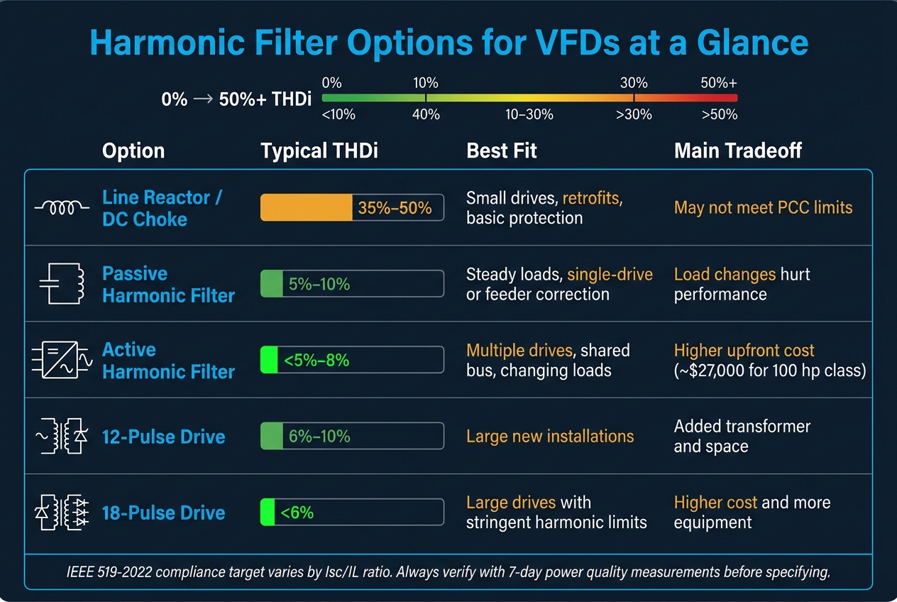
Harmonic Filter Options for VFDs: THDi, Cost & Best Fit Compared
| Option | Typical THDi | Best fit | Main tradeoff |
|---|---|---|---|
| Line reactor / DC choke | 35%–50% | Small drives, retrofits, basic drive protection | May not meet PCC limits |
| Passive harmonic filter | 5%–10% | Steady loads, single-drive or feeder correction | Load changes can hurt performance |
| Active harmonic filter | <5%–8% | Multiple drives, shared bus, changing loads | Higher upfront cost |
| 12-pulse drive | 6%–10% | Large new installs | Added transformer and space |
| 18-pulse drive | <6% | Large drives with tighter limits | Higher cost and more gear |
My takeaway: pick the simplest option that still meets the limit, then verify it with measured data, a harmonic study, and post-install testing.
sbb-itb-501186b
Harmonic Mitigation Options for Drives
Use THDi, THDv, and Isc/IL to narrow the field. In plain terms: reactors handle basic harmonic reduction, passive filters fit fixed loads, active filters fit changing loads, and multipulse setups make the most sense for new, large drives.
| Option | Typical THDi at Full Load | Best Fit |
|---|---|---|
| Line reactor / DC choke | 35–50% | Small drives, retrofits, basic protection |
| Passive harmonic filter | 5–10% | Stable loads, drive-level or feeder compliance |
| Active harmonic filter | <5–8% | Varying loads, plant-level correction |
| 12-pulse drive | 6–10% | Large drives, new installations |
| 18-pulse drive | <6% | Large drives, stringent harmonic limits |
Line Reactors and DC Link Chokes
A line reactor on the AC input, or a DC link choke on the DC bus, adds 3% or 5% series impedance. That extra impedance smooths rectifier current and helps the drive ride through surges better.
Without added impedance, a six-pulse VFD can push past 100% THDi. Add a 3% line reactor, and THDi often drops into the 35–45% range. Move to 5% impedance, and it often gets closer to 30–35%, though the exact result still depends on supply stiffness and load profile. DC link chokes usually do a bit better on the 5th and 7th harmonics, while AC line reactors are often simpler to retrofit into existing MCCs or panelboards.
For drives under 50 hp, where VFDs make up only a modest share of the site load - usually under 20–25% of total kVA - a reactor or choke is often enough. The catch is simple: a 5% reactor adds about 2–3% voltage drop at full load. So check that the voltage drop is acceptable, and make sure the reactor's short-circuit rating matches the available fault current.
If THDi or TDD is still too high after that, it's time to step up to a tuned filter or an active filter.
Passive and Active Harmonic Filters
Passive filters work best when the load stays fairly steady, THDv is low, and voltage unbalance is low. If the load shifts around too much, the tuning can drift and resonance risk can go up. That makes passive filters a better match for one or a few problem drives, not every messy system. When several drives share a bus and the goal is PCC-level correction, a centralized active filter is usually the better call.
An active harmonic filter (AHF) uses power electronics to track the harmonic spectrum in real time and inject canceling currents at the bus. When sized the right way, it can usually keep THDi below 5–8% at the PCC. That flexibility is the big selling point.
The drawback is price. A 100 hp-class active filter runs about $27,000, while a low-pass passive filter at the same size costs about $5,600.
For new large drives, multipulse setups can hit similar distortion levels without adding an external filter.
12-Pulse and 18-Pulse Drive Setups
Multipulse drives are usually picked during design for new installations. They use phase-shifting transformers to feed two or three separate six-pulse rectifier bridges. Each bridge is offset by a set angle, which lets the main low-order harmonics - especially the 5th, 7th, 11th, and 13th - cancel part of each other.
A 12-pulse setup usually lands around 6–10% THDi at nominal load. An 18-pulse setup can get below 6% THDi, and it often meets IEEE 519 at the drive terminals without an external filter. These setups show up most often on drives in the 200–1,000 hp range and above, where the added cost of the phase-shifting transformer and multi-bridge rectifier is easier to justify. Think large pumps, compressors, and chiller drives.
Retrofit is a different story. In many cases, it means replacing the transformer, changing the rectifier topology, and reworking cabling and switchgear.
How to Size and Specify the Right Filter
After you choose the mitigation method, the next step is simple in theory and easy to get wrong in practice: size it from measured field data and check the limits of the actual installation.
Start with Power Quality Measurements and Load Data
Before you choose any filter, log data from the live system. Nameplate values don't tell the whole story. Use a power quality analyzer to record RMS voltage, RMS current, kW, THDi, THDv, and harmonic magnitudes through the 25th order at the drive terminals for a single drive, or at the common bus for multiple drives.
Run the logging for at least 7 days so you catch shift changes, startup events, and low-load periods. If the process is batch-based or the load moves around a lot, stretch that window to 2–4 weeks to get a better picture of how the system behaves. Pay close attention to peak THDi, the main harmonic orders, and how much the load swings across the production cycle.
You should also get the available fault current at 480 V from utility records or from a short-circuit study. That value affects both filter choice and protection setup.
Use the readings to do two things:
- Set the device rating
- Confirm whether you're sizing for one drive or for a shared bus
Match the Filter to the Drive and the System
For reactors and passive filters, size to the drive's full-load current and then add margin. A 10–25% oversize is standard practice. The high end of that range makes more sense when the drive stays near 100% load for long periods or the ambient temperature runs hot.
For multiple drives on a shared 480 V bus, don't size from summed nameplate current alone. That's a common trap. Use measured diversity, not assumed diversity. On shared buses, size from the measured peak bus current and then add 10–25%.
Active filters are sized a bit differently. Base them on measured harmonic current, then add 20–25% headroom.
Once you've set the rating, check SCCR, resonance, and enclosure fit before you buy anything.
Check Protection, Resonance, and Installation Limits
Start with SCCR. The filter assembly SCCR has to meet or exceed the available fault current. In a combined assembly, the part with the lowest rating sets the SCCR for the whole setup. Current-limiting fuses can increase it.
For breaker and fuse coordination, review the time-current curves so upstream devices clear faults without nuisance trips during normal harmonic operation. Passive filters can add inrush or reactive current at energization, so protective settings need to account for that. Ask manufacturers to include recommended protective device types and maximum ratings in their submittal package.
Resonance is another place where things can go sideways. If the facility uses power factor correction capacitor banks, run an impedance scan. Adding a passive filter or a large reactor can move the system's natural resonant frequency right onto a dominant harmonic. When that happens, distortion can get worse instead of better. Model the transformer, cable, capacitor-bank, and filter impedances together before installation to make sure you don't create harmful resonance.
Last, check the enclosure and cooling against the installation space. Most filter ratings assume 104 °F (40 °C) ambient. Rooftops, mechanical rooms near heat sources, and poorly ventilated electrical rooms can run hotter than that. If they do, you may need derating, oversizing, or forced cooling. Use NEMA 1 or 12 indoors. Use NEMA 3R, 4, or 4X outdoors or in washdown areas. Also make sure clearances and cable routing work before you lock in the final filter footprint.
Choosing the Right Option for Your Facility
Pick the simplest option that still meets the limit. In practice, that means looking at three things first: load stability, your compliance target, and lifecycle cost. Start with the measured load profile. That usually helps trim the list fast before you get into protection needs and installation limits.
When a Reactor Is Enough
For drives under 50 hp, when VFDs make up only a modest share of the site load, a line reactor or DC link choke is often enough. If THDi or TDD stays within IEEE 519 limits after adding 3–5% impedance, you usually don’t need more mitigation.
When Passive or Active Filters Make More Sense
A passive filter tends to fit best when loads stay steady and operate near full output, especially when one harmonic order stands out. An active filter makes more sense when several drives share a bus and operating conditions change often.
This is where people sometimes look only at the upfront price and miss the bigger picture. Heat loss affects both operating cost and panel temperature, so compare total cost of ownership, not just the purchase price.
There’s also a middle ground. If loads vary across the system, a passive filter on high-use drives paired with a smaller active filter for system-wide correction can cut both cost and heat. Put simply:
- If the load is stable, stay with passive.
- If the load changes often, move to active.
When Multipulse Is Worth the Added Equipment
Use 12- or 18-pulse only when the project can absorb the transformer, footprint, and added upfront cost. That usually points to new designs with enough room for the transformer and the extra drive hardware.
After you choose the filter type, check protection, resonance, and enclosure limits before purchase.
Implementation, Sourcing, and Final Checklist
From Assessment to Commissioning
Once you’ve set the filter type and rating, the next step is field verification and commissioning. Start with a power quality audit. Document the main nonlinear loads, then log THD, dominant harmonic orders, and load profiles at the PCC and major drive feeders for at least 7 days with a calibrated Class A analyzer.
After that, run a harmonic study using your measured data and system details. That includes transformer impedance, short-circuit capacity, feeder lengths in feet, and existing protective device data. The goal is simple: confirm how the selected filter will behave in the actual system, not just on paper.
Once the study sets the spec, lock down the installation details and protection settings before procurement. Your purchase documents should call out:
Follow NEC/NFPA 70 for conductors, clearances, grounding, and bonding. After energization, measure THD again under the same load conditions used during the first study. Comparing pre- and post-installation THD readings against IEEE 519-2022 limits gives you documented proof for inspections and utility review.
Sourcing Related Power Equipment for Filter Projects
If the project also needs supporting gear, source it during the same procurement cycle. That usually saves time and cuts down on surprises later.
Adding filters or moving to multipulse drives often brings up nearby equipment needs. You may find that the job now calls for a transformer with different impedance, a breaker with a higher interrupting rating, or a panelboard that needs to be reworked.
Electrical Trader carries breakers, transformers, and low-to-high voltage distribution equipment, so it can be a practical place to look when a filter project also needs supporting gear. Using one marketplace can make it easier to compare options for price, lead time, and condition when the schedule is tight.
Before Purchase, Confirm the Three Nonnegotiables
Before release to purchase, verify the measured harmonic spectrum, resonance risk, and SCCR.
FAQs
How do I know if I need THDi or PCC compliance?
Use an IEEE 519 harmonic analysis to see whether your facility needs to meet THDi limits at the PCC.
If your site has non-linear loads like VFDs, rectifiers, UPS systems, or EV chargers, measure distortion at the PCC. Then compare those results with IEEE 519 limits based on system voltage and your short-circuit-to-demand current ratio.
If your readings are over the limit, or if resonance is present, you may need mitigation.
Can a line reactor be enough for my VFD?
Yes - a line reactor can be enough for a VFD if you want basic protection and a modest cut in harmonics.
It helps protect drive rectifiers from power-line transients. It can also reduce current harmonic distortion by 30% to 50%.
That said, it may not be enough if your facility needs to meet IEEE 519 or if harmonics and resonance are more complicated. In those cases, you may need added filtering.
When should I choose active over passive filtering?
Choose active filtering for dynamic settings with VFDs or fast-changing loads that shift the harmonic spectrum. It can reduce a broad range of harmonics, deal with multiple harmonic orders up to the 50th, and react in real time.
It also makes sense when floor space is tight or IEEE 519 compliance is a must. Passive filters usually make more sense for stable, predictable, budget-conscious setups.





