




How Harmonics Impact Reactive Power Compensation
Harmonics can disrupt reactive power compensation systems, leading to equipment failure, reduced efficiency, and increased energy losses. Non-linear loads like variable frequency drives (VFDs) and LED lighting generate these distortions, which can cause overheating, resonance, and degraded power factor correction. Avoiding these issues requires careful system design, harmonic analysis, and the right mitigation technologies such as passive, active, or hybrid filters.
Key Takeaways:
- Harmonics: Distorted electrical waveforms caused by non-linear loads.
- Impact: Overheating components, resonance, reduced power factor, and higher Total Harmonic Distortion (THD).
- Mitigation Options: Passive filters (cost-effective but fixed), active filters (dynamic but expensive), and hybrid systems (a balance of cost and performance).
- Best Practices: Conduct harmonic studies, follow IEEE 519 standards, and size equipment properly to prevent resonance and ensure compliance.
Understanding and addressing harmonics is critical for maintaining power quality, protecting equipment, and ensuring system stability.
Harmonic problem solutions. Part III.A (Reactive power compensation) - Harmonics in EPS #18
sbb-itb-501186b
How Harmonics Degrade Reactive Power Compensation Systems
Harmonics can seriously undermine reactive power compensation systems in three major ways. For those managing electrical distribution setups with capacitor banks, it's crucial to grasp how these issues arise and their potential impact.
Resonance Problems in Passive Filters
Harmonics can trigger resonance issues in capacitor banks, which all have a natural resonant frequency. When this frequency overlaps with harmonics from nonlinear loads, problems arise. In parallel resonance, small harmonic currents can escalate into hazardous voltages and circulating currents due to the high-impedance path created - further intensified by the Q-factor (commonly between 5 and 30). On the other hand, series resonance forms a low-impedance path, pulling excessive current from the grid even if nonlinear loads aren't significant on-site.
To predict resonance in your system, use this formula:
h₍R₎ = √(MVA₍SC₎ / MVAR₍CAP₎),
where MVA₍SC₎ is the bus's short-circuit MVA, and MVAR₍CAP₎ is the capacitor bank rating. If the result shows resonance near the 5th harmonic (300 Hz) or 7th harmonic (420 Hz) - frequencies often linked to variable frequency drives - your system is at risk.
"Harmonic resonance is said to be a self-correcting problem. Most times capacitor fuses will open, capacitor cans will fail, or the source transformer fails... However, they're all undesirable results."
– Daniel J. Carnovale, P.E., Eaton/Cutler-Hammer
A real-world example highlights the dangers: a facility's voltage distortion jumped from below 2% THD to 6.9% THD when nonlinear loads were activated. The 13th harmonic current surged to 120 A - 44.6% of the fundamental current - causing the RMS current to rise from 236 A to 311 A. This led to heating losses that were 2.48 times higher than normal. Beyond resonance, such harmonics degrade power factor correction and increase total harmonic distortion (THD).
Lower Power Factor Correction Performance
Harmonics also compromise the effectiveness of capacitors in improving power factor. Standard power factor correction systems mainly address the displacement power factor - the phase shift between voltage and current at the fundamental frequency of 60 Hz. However, true power factor accounts for harmonic distortion as well. Since capacitive reactance decreases sharply with frequency - dropping to about 20% at the 5th harmonic and 7.7% at the 13th - capacitors absorb excessive harmonic currents. This can end up worsening the overall power factor, despite correcting the displacement component.
The I²R relationship means even modest harmonic levels lead to significant heating. For instance, with just 10% voltage THD, Joule losses in capacitors can increase by 40%. If harmonic power exceeds 10% of the system's total power, it can result in severe overvoltages and overloads, accelerating equipment failure.
Higher Total Harmonic Distortion (THD)
Harmonic currents increase the system's RMS load, adding stress to all components. The formula
I₍rms₎ = I₍₁₎ √(1 + THDᵢ²)
shows how this elevated current affects the entire distribution system - transformers, conductors, switchgear, and especially capacitor banks.
The fallout isn’t limited to reactive power equipment. A supply voltage with 10% THD can shorten the lifespan of single-phase machines by 32.5%, three-phase machines by 18%, and transformers by 5%. In three-phase, four-wire circuits serving electronic loads, neutral currents can be about 70% higher than phase currents due to triplen harmonics.
Harmonics also interfere with control circuits. They create multiple zero crossings in the voltage waveform, which can disrupt the crossing detectors in power factor correction controllers. This leads to erratic switching, incorrect measurements, and unreliable operation. A striking example occurred in February 2023 at a pharmaceutical lab, where harmonics caused a generator set to fail during a critical test for a new medication. The estimated loss? Around $18 million.
Comparing Reactive Power Compensation Technologies
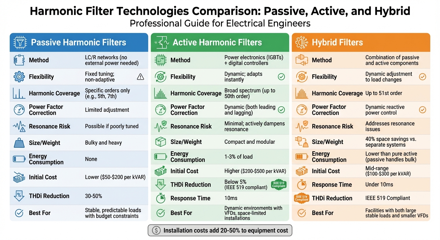
Comparison of Passive, Active, and Hybrid Harmonic Filters for Reactive Power Compensation
When dealing with harmonics, not all reactive power compensation technologies operate at the same level. Selecting the right solution - whether passive filters, active filters, or hybrid systems - can make all the difference in mitigating harmonics and avoiding expensive equipment issues. Here's how these technologies stack up for different load profiles.
Passive Filters vs. Active Filters
Passive filters rely on LC circuits to create a low-impedance path for specific harmonic frequencies, like the 5th or 7th orders. While they’re effective for targeted harmonics, they lack flexibility. If your load profile changes, their performance can drop significantly.
On the other hand, active filters use advanced power electronics, such as IGBTs and digital controllers, to cancel harmonics in real time. These filters respond in as little as 10ms, handling harmonics up to the 50th or 51st order. They also dynamically adjust for both leading and lagging power factor correction, making them highly adaptable to fluctuating loads.
"Active harmonic filters are fundamentally superior for the primary goal of effective harmonic mitigation."
– Shanghai Yingtong Electric Co., Ltd.
The trade-offs? Passive filters are more affordable upfront and need minimal maintenance. However, they are fixed in design and non-adaptive. Active filters, while pricier and consuming 1–3% of the load to operate, are compact, safe from resonance issues, and capable of reducing total harmonic distortion (THDi) to below 5%, meeting IEEE 519 standards. In comparison, basic passive solutions like line reactors only reduce THDi by 30–50%.
| Feature | Passive Harmonic Filter | Active Harmonic Filter |
|---|---|---|
| Method | LC/R networks (no external power) | Power electronics (IGBTs) + digital controllers |
| Flexibility | Fixed tuning; non-adaptive | Dynamic; adapts instantly |
| Harmonic Coverage | Specific orders only (e.g., 5th, 7th) | Broad spectrum (up to 50th order) |
| Power Factor Correction | Limited adjustment | Dynamic (both leading and lagging) |
| Resonance Risk | Possible if poorly tuned | Minimal; actively dampens resonance |
| Size/Weight | Bulky and heavy | Compact and modular |
| Energy Consumption | None | Consumes about 1–3% of the load |
| Initial Cost | Lower | Higher |
Passive filters are ideal for stable, predictable loads where budget is a major concern, and only a few harmonic orders need addressing. Active filters shine in dynamic environments with variable frequency drives (VFDs), where space is limited, and IEEE 519 compliance is essential.
For situations where neither passive nor active filters alone can meet performance needs, hybrid systems offer a middle ground.
Hybrid Compensation Systems
Hybrid systems blend passive and active components, striking a balance between cost and performance in environments with high harmonic distortion. The passive section targets the bulk of lower-order harmonics, while the active section compensates for fluctuating harmonics that passive filters can’t handle effectively. Like active filters, hybrid systems adjust dynamically to load changes, ensuring consistent harmonic mitigation and reactive power control.
This division of labor allows the active filter portion to be smaller and less powerful than a standalone active system, reducing both size and cost. Hybrid systems can save up to 40% of space compared to separate passive and active setups while maintaining strong performance at a mid-range price point.
"Since the [passive filter] takes care of the major burden of compensation, the rating of the shunt hybrid power filter is much smaller than that in the conventional shunt active power filter."
– Hsan et al., SpringerPlus
Hybrid systems also address common problems like resonance, a frequent issue with purely passive setups. Advanced designs can mitigate harmonics up to the 51st order while providing load balancing and voltage stabilization, all with a response time under 10ms. Some systems even switch modes in real time, acting as either a power factor corrector or a power quality booster, depending on the load.
Hybrid solutions work best in facilities with both large, stable nonlinear loads and smaller VFDs. They’re particularly useful for targeting specific harmonic orders, like the 11th, which may cause resonance. For easier installation and reduced costs, look for integrated hybrid systems requiring just one breaker and a single cable set.
Designing Systems to Manage Harmonics
Addressing issues like resonance and performance degradation requires careful attention to system design. Missteps in sizing, placement, or skipping harmonic analysis can lead to significant problems. Here's how to approach it effectively.
System Sizing and Point of Common Coupling (PCC) Placement
Getting the sizing right is key to avoiding resonance. Use this formula to determine the resonant frequency before installing capacitor banks:
h = √(kVA₍sc₎/kVAR).
If the calculated frequency matches problem harmonics (like the 5th, 7th, or 11th), adjust the capacitor bank size or include series inductors to shift the circuit's resonance away from those frequencies.
Placement is just as important as sizing. Installing capacitors at the PCC can improve utility billing metrics, but it won't reduce harmonic losses within the facility. To cut down on internal losses, place capacitors closer to major inductive loads.
"The current reduction will take place from the capacitor installation point back to the utility point of connection, not forward within the distribution system, itself"
– Consulting-Specifying Engineer Staff
For systems with multiple kVAR correction steps, calculate resonance for each potential level of correction. Resonance points shift with every switched step, so it's crucial to account for these changes. Additionally, harmonic filters should be placed on buses with stable short-circuit impedance. This prevents the resonant frequency from drifting during operational changes, such as switching to standby generators.
Finally, analyze the system's harmonic profile to ensure compliance with IEEE 519 standards.
Harmonic Analysis and IEEE Standard 519 Compliance
IEEE 519 compliance is evaluated at the PCC, usually at the utility-transformer secondary. For systems under 1 kV, aim for a Total Harmonic Voltage Distortion (THDv) below 5% to 8% and individual harmonic voltage distortion below 3%. For systems up to 69 kV, the limits are 5.0% for voltage THD and 3.0% for individual harmonics.
Current distortion limits depend on the Short Circuit Ratio (SCR) of your system. Here's a quick breakdown of Total Demand Distortion (TDD) limits by SCR:
| SCR (Short Circuit Ratio) | TDD Limit |
|---|---|
| < 20 | 5.0% |
| 20 to < 50 | 8.0% |
| 50 to < 100 | 12.0% |
| 100 to < 1000 | 15.0% |
| ≥ 1000 | 20.0% |
Harmonic distortion analysis should be part of the planning phase for new facilities or expansions. This avoids the need for costly retrofits later. Measure power quality over 24–72 hours to capture accurate load profiles and peak harmonic currents. When adding power factor correction capacitors, conduct a harmonic study to ensure they don't cause resonance with system inductances.
Another useful tactic is "dilution" - operating nonlinear loads like variable frequency drives (VFDs) alongside linear loads such as motors or resistive heating. This can naturally reduce overall harmonic distortion.
With harmonic analysis complete, the next step is selecting the right equipment.
Choosing the Right Equipment
Start by identifying harmonic sources, such as VFDs, UPS systems, rectifiers, and EV chargers. Gather data on Total Harmonic Distortion of Current (THDi), individual harmonic orders (e.g., 5th, 7th, 11th, 13th), and whether your loads are constant or variable. Calculate the required rating by measuring harmonic current (Ah), setting a target THDi (typically below 5% per IEEE 519), and adding a 10–20% safety margin.
Ensure power capacitors can handle a continuous RMS overvoltage of 110% and an overcurrent of 180% of their nameplate rating, with a total VA rating under 135%. For filter applications, use capacitors with a higher voltage rating than your system - for example, 600 V capacitors for a 480 V system. This ensures they can handle harmonic overvoltages, though it reduces their effective kVAR to 64%.
When designing passive notch filters, tune the filters slightly below the target harmonic frequency (e.g., 4.7th order for a 5th harmonic). This creates a buffer for component tolerances and temperature changes. Always install filters starting with the lowest harmonic order (e.g., 5th before 7th) to avoid retuning the system to a lower-order resonance.
"It is generally good practice to apply filters starting at the lowest characteristic harmonic to avoid this problem [of retuning the system to a lower harmonic]"
– Electrotek Concepts, Inc.
Cost considerations:
- Fixed capacitors: ~$25 per kVAR
- Stepped capacitors: ~$40 per kVAR
- Passive harmonic filters: $50–$200 per kVAR
- Active harmonic filters: $200–$500 per kVAR
- Hybrid filters: $100–$300 per kVAR
Installation costs typically add 20% to 50% of the equipment cost.
With a well-designed system, you can sidestep resonance issues while improving power quality and extending system life.
Conclusion
Harmonics don't just interfere with reactive power compensation - they can jeopardize the entire system's stability. The consequences are serious: resonance can amplify distortion to dangerous levels, a mere 10°F temperature rise can cut equipment life in half, and nuisance tripping disrupts operations when you least expect it. The good news? These issues can be prevented with the right strategies.
Start by conducting a harmonic analysis before integrating capacitors. Make sure to assess resonant frequencies to avoid aligning with troublesome harmonics like the 5th or 7th. If your system includes nonlinear loads such as VFDs, UPS systems, or rectifiers, opt for solutions like detuned reactors or passive filters instead of standard capacitor banks. For systems with dynamic loads, active filters provide greater flexibility, though they come at a higher cost - around $200–$500 per kVAR compared to $50–$200 for passive alternatives.
Stay aligned with IEEE 519 standards. For systems under 69 kV, voltage THD should remain below 5%, while current TDD limits depend on your Short Circuit Ratio. Regular monitoring using power quality analyzers can help you identify and address issues early. When planning new systems or expansions, incorporate harmonic mitigation from the outset. Retrofitting later can be both costly and time-intensive. By taking these steps, you can ensure your reactive power compensation strategy remains effective and resilient.
FAQs
How do I know if my capacitor bank will resonate with harmonics?
To determine if your capacitor bank might resonate with harmonics, you’ll need to examine the system’s inductance, capacitance, and the harmonic frequencies generated by non-linear loads. The interaction of these elements can lead to harmonic resonance, which can cause significant issues if left unaddressed. By carefully analyzing system parameters and designing appropriate harmonic filters, you can identify and mitigate potential resonance risks effectively.
What’s the difference between displacement power factor and true power factor?
Displacement Power Factor (DPF) represents the cosine of the phase angle between voltage and current at the fundamental frequency, usually 60 Hz. It highlights the phase alignment in linear loads, such as inductors or capacitors. On the other hand, True Power Factor goes further by combining DPF with the distortion power factor. This includes the effects of harmonic distortions caused by non-linear loads like power electronics, offering a broader view of electrical power efficiency.
Should I choose a passive, active, or hybrid filter for my facility?
The best harmonic filter for your system depends on your power setup and the specific harmonics you're dealing with.
- Passive filters are a budget-friendly choice when dealing with a single, large nonlinear load. However, they come with a potential downside: the risk of resonance in certain conditions.
- Active filters are a more dynamic option, capable of managing multiple nonlinear loads at once. They work across a range of frequencies to enhance overall power quality.
- Hybrid filters blend the strengths of both passive and active filters, making them a solid choice for more intricate systems requiring efficient harmonic control.
If your needs are straightforward, passive filters might do the trick. But for more adaptable and comprehensive solutions, active or hybrid filters are better suited.





