7 Harmonic Effects on Transformer Losses and Heat
If your transformer feeds VFDs, UPS systems, LED loads, or EV chargers, harmonics can make it run hotter even when the kVA looks normal.
I’d sum it up like this: harmonics add extra current, extra loss, and extra heat. That heat can push temperatures up by 10–20°C (18–36°F), cut usable transformer capacity, overload neutrals, and shorten insulation life. In many buildings, voltage THD stays around 3%–5%, but current THD can hit 20%–40% or more.
Here’s the full picture in plain English:
- Copper losses go up because distorted current lifts RMS current, and I²R loss goes up fast.
- Core losses go up when voltage distortion changes the flux wave shape.
- Triplen harmonics like the 3rd can stack in the neutral and overheat it.
- Insulation ages faster when hot-spot temperature stays too high.
- Noise and vibration increase as harmonic frequencies add extra mechanical stress.
- Derating may be needed, often when THD moves past 5%, and a formal check is smart above 15%.
- Service life drops when that extra heat stays in the transformer day after day.
A few field checks tell you a lot:
- Measure current THD with a true-RMS power quality analyzer
- Check neutral current against phase current
- Use IR scans to spot hot bars, lugs, and tank areas
- For liquid-filled units, review DGA if heating is suspected
| Effect | What heats up | What you may see |
|---|---|---|
| Higher copper loss | Windings, leads | Higher winding temperature, hot spots |
| Higher core loss | Core, clamps, tank parts | Extra no-load heat, more hum |
| Neutral overload | Neutral conductor, terminations | Hot neutral, damaged insulation |
| Insulation stress | Winding insulation | Faster aging, failure risk |
| Noise and vibration | Core, clamps, mounting parts | Buzzing, whining, shaking |
| Derating need | Whole transformer | Overtemperature at normal load |
| Shorter life | All heat-sensitive parts | More faults, earlier replacement |
Bottom line: if you see THD above 5%, hot spots, or a neutral current near or above phase current, don’t rely on nameplate kVA alone. Check harmonic loading, temperature, and transformer margin before heat turns into failure.
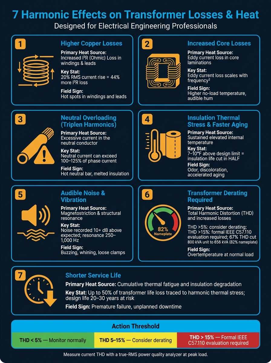
7 Harmonic Effects on Transformer Losses, Heat & Service Life
How Do Harmonics Impact Transformer Performance? - Electrical Engineering Essentials
sbb-itb-501186b
Why Harmonics Make Transformers Run Hotter
Harmonic current pushes a transformer’s RMS current above what it was built to handle, which drives losses past design limits. The result is more heat in both the windings and the steel parts. The first place this shows up is usually in the windings.
Non-linear loads pull current in 3rd, 5th, 7th, and higher-order harmonic components. That lifts RMS current, and higher RMS current means more winding heat. Copper loss follows the square of current, so even a modest jump matters: a 20% RMS increase lifts I²R loss by about 44%. On top of that, eddy-current losses climb with harmonic order, so higher-order currents can create hot spots in windings and nearby metal parts. That heat doesn’t stay put. It spreads into the core and tank too.
Voltage harmonics add another problem by distorting the flux waveform and increasing core loss. Instead of a smooth sine wave, the core sees sharper peaks and more frequent reversals. That drives up both hysteresis loss and core eddy-current loss. Higher-order harmonics can also create localized hot spots in windings, clamps, tank walls, and other metal parts that a kVA rating won’t show.
So this isn’t just one loss mechanism acting alone. Harmonics hit several loss paths at the same time. In practice, the first sign is often higher winding heat, even though the extra loss is also building in the core and nearby metal parts.
These loss mechanisms show up first as higher winding heat. Those losses create the seven effects below.
1. Higher Copper Losses and Winding Heating
Harmonic current pushes up RMS current, and copper loss climbs with I²R. In plain English: when current gets distorted, the transformer runs hotter.
That’s a common issue with non-linear loads like VFDs, UPS systems, LED drivers, and EV chargers. These loads can drive RMS current above the fundamental value, which pushes winding losses well beyond what the unit was built to handle. A load with 30% to 40% current THD can increase copper losses by tens of percent compared with a sinusoidal load at the same kVA rating. And that extra heat in the windings isn’t the whole story. Harmonic distortion also increases core loss.
Higher-order harmonics make winding resistance act higher than it would under a clean sine wave. That, in turn, increases eddy-current heating in the windings and in nearby metal parts.
The practical outcome is derating. Even if the kVA load looks fine on paper, the transformer may not be able to carry it safely. In one documented case, 67% THD cut an 800 kVA transformer down to about 656 kVA, or 82% of nameplate, to keep temperature rise under control. That’s a big hit to usable capacity.
The main danger is localized hot spots. Those spots can run past design limits even when the average temperature still looks normal. And transformer insulation doesn’t forgive extra heat for long. Running a transformer just 5°F to 9°F above its rated temperature can cut insulation life by about half.
To check the risk, use a true-RMS analyzer to measure current THD and the harmonic spectrum. From there, calculate K-factor or the harmonic loss factor under IEEE C57.110. That gives you a better read on added loss and helps you size the transformer the right way.
If winding heating shows up first, core loss usually isn’t far behind.
2. Increased Core Losses
Winding loss is only part of the issue. When voltage gets distorted, the core flux is no longer a clean sine wave. That means the core has to handle higher-frequency flux components it was never built to handle, which increases hysteresis and eddy current losses in the steel laminations.
Here’s the key difference: winding loss tracks current, but core loss tracks distorted voltage. So core loss can climb even when load current stays flat. In plain terms, a transformer can run hotter than expected even when the current still looks moderate on paper. In some cases, the core itself becomes a major source of heat. And yes, core heating can show up even at light load.
Higher-order harmonics are a big part of the problem because eddy current losses scale roughly with the square of frequency. A small jump in frequency doesn’t lead to a small jump in loss. It can hit much harder than that. The result can be higher tank temperature and more no-load loss, even when kVA appears normal.
That’s why facilities packed with VFDs, LED drivers, or UPS loads may see core temperatures climb even when average kVA doesn’t look alarming.
3. Neutral Overloading from Triplen Harmonics
Triplen harmonics don't just warm up windings and cores. In four-wire systems, they can also hit the neutral path hard.
Here's the problem: triplen harmonics can overload the neutral and circulate in delta windings, which adds more heat to the transformer. The 3rd, 9th, and 15th harmonics add in the neutral instead of canceling out. They are zero-sequence components, so they stay in phase across all three phases. Because of that, neutral current can equal the sum of the phase triplen currents.
That heat comes from I²R loss in the neutral conductor, terminations, and bus bars. Under heavy triplen loading, neutral current can climb past phase current. Harmonic frequencies can also increase resistance and heating through skin effect. Put together, that extra neutral heat adds to the transformer's total temperature rise.
This is where things get dicey. Neutral overheating is risky because neutrals often do not have overcurrent protection. In many cases, the first signs are loose terminations, insulation damage, or outright conductor failure. And inside delta windings, triplen currents can circulate and add copper and stray-loss heating.
A good first check is simple: use a clamp-on RMS ammeter on the neutral. If neutral current stays above about 100% to 125% of phase current, there's a good chance you have heavy triplen content. Infrared thermography on neutral bars and terminations can spot hot areas before they turn into failures. If you want to see the source more clearly, use a power quality analyzer that shows the harmonic spectrum, especially the 3rd, 9th, and 15th.
To cut the risk, common fixes include:
- A 150% to 200% neutral
- K-factor-rated transformers
- Zig-zag or harmonic-mitigating transformers
- Better balancing of nonlinear loads
These steps are commonly used to deal with triplen-related heating and neutral loading.
That extra thermal stress also pushes insulation toward faster aging.
4. Insulation Thermal Stress and Faster Aging
As winding losses go up, insulation often becomes the next weak link. Harmonics push winding temperature higher through I²R, skin, and proximity losses, and the insulation ends up paying the price. The winding hotspot matters more than the average temperature. Top-oil temperature can look perfectly normal while the winding hotspot is already above safe limits.
Insulation aging speeds up fast. Transformer insulation follows an Arrhenius-type thermal aging law, which means aging does not rise in a straight line with temperature. It climbs exponentially instead. A hotspot just 7–10°F (about 4–6°C) above the design limit can cut insulation life in half, even when kVA still looks normal.
Once insulation starts to weaken, failure risk goes up with it. Paper and varnish lose dielectric strength, which increases the chance of partial discharge, winding faults, and moisture damage.
One distribution transformer study found that roughly 50% of transformer life reduction in some environments could be traced directly to thermal stress from harmonic currents.
The best move is to catch this early. In day-to-day practice, that usually means combining:
- Current THD measurement
- Winding or hotspot temperature trending
- Infrared thermography
- For liquid-filled units, periodic dissolved gas analysis (DGA)
One reading won't tell you much. Trends matter. Harmonic loading can change by shift, season, and production cycle. So if temperature rise stays higher than expected for the load, harmonics are a strong suspect.
As insulation ages, noise and vibration often increase next.
5. Audible Noise and Vibration
Heat isn't the only clue that harmonics are stressing a transformer. Noise and vibration matter too. The main driver is magnetostriction: core steel changes shape slightly as it becomes magnetized, which produces the familiar 120 Hz hum in a 60 Hz system. When harmonic flux enters the picture, it adds extra tones beyond that normal hum. The result is more buzzing and whining layered on top of the baseline sound.
Those extra tones also stand out more to people nearby. Higher-frequency sound is easier for the ear to notice, so even modest harmonic content can seem much louder than the base hum. In field installations, transformer noise has been recorded at more than 10 dB higher than expected, in part because harmonic loading and site acoustics differ from controlled test settings.
The 5th and 7th harmonics, which are common in six-pulse VFDs and rectifiers, create winding forces that can excite resonances in the 250–1,000 Hz range. Triplen harmonics can also increase core vibration through zero-sequence flux in three-phase, four-wire systems.
This isn't just annoying background noise. Over time, repeated high-frequency cycling can loosen core clamps and wear down winding supports. In plain terms, the transformer can start to shake itself apart.
Two checks can help confirm that harmonics are the cause:
- A power quality analyzer shows current THD above 15–20%, and a sound level meter detects clear tonal peaks at multiples of 60 Hz.
- The noise drops when nonlinear loads are reduced or when filters are switched in.
That pattern points to harmonic loading, not just a plain mechanical fault. To verify it, use a power quality analyzer, sound level meter, and vibration sensor.
If the noise rises and falls with harmonic loading, the next step is figuring out whether the transformer now needs derating.
6. Transformer Derating Requirements
Once harmonic heating is confirmed, the next step is derating. Harmonics can drive transformer temperature past design limits, which means the usable capacity may end up lower than the nameplate rating.
IEEE C57.110 uses the harmonic loss factor and K-factor to estimate how much load a transformer can carry without going past hotspot limits. In most cases, winding stray losses are what drive derating decisions, because those losses climb fastest as harmonic frequency goes up.
Use these thresholds:
| Current THD Level | Recommended Action |
|---|---|
| Above 5% | Consider derating. |
| Below 15% | Derating is usually small and may be neglected. |
| Above 15% | Formally evaluate capability per IEEE C57.110. |
Under heavy harmonic loading, running at full nameplate can push hotspot temperature beyond design limits.
K-rated transformers are built for harmonic duty. They use heavier conductors and reinforced windings so they can handle higher K-factors at or near full nameplate load. That often cuts the need for deep derating in harmonic-heavy settings.
For existing units, a common starting point is to limit loading to about 70% to 80% of nameplate when THD or K-factor is high, then verify hotspot temperature with IR scans. If derating still doesn't keep heat under control, service life drops next.
7. Shorter Service Life and Reduced Reliability
The heating effects covered so far - higher copper losses, core losses, neutral overloading, and insulation stress - don’t just create short-term trouble. They build up over time and slowly wear down the transformer’s expected service life. What starts as extra heat often ends as insulation aging and lower reliability.
The biggest weak point is the insulation. As hot-spot temperature goes up, aging speeds up and service life gets cut down. A transformer built to last 20–30 years under rated sinusoidal load can wear out much faster when harmonics drive hot-spot temperatures into the 110–120°C range and beyond.
Research shows that up to 50% of transformer service-life loss can come straight from thermal stress caused by harmonic currents when no mitigation is in place. That means shorter replacement cycles and a higher risk of outages.
From a reliability angle, this isn’t only about slow wear. Once insulation starts to break down, the chance of insulation failure and internal faults goes up too. And those failures can knock a transformer offline with little warning. If a critical load depends on a single transformer, untracked harmonic aging can turn into direct downtime risk.
That’s why ongoing monitoring matters. Keep an eye on:
- Hot-spot temperature
- Current THD
- Neutral-to-phase current ratio
A neutral-to-phase current ratio above 1.2 points to triplen overload and extra heating. In liquid-filled units, dissolved gas analysis (DGA) can spot early thermal stress before it turns into a failure.
Quick Reference Table: Harmonic Effect, Heat Impact, and Typical Response
These seven effects often show up together. This table helps you link each issue to the heat source behind it and the first step to take.
| Harmonic Effect | Loss Path | Primary Heat Source | Field Signs | Typical Response |
|---|---|---|---|---|
| Higher copper losses | Winding and lead heating | Windings, leads, terminals, bus bars | Hot transformer tank, winding hot spots, reduced efficiency | Review K-factor, derate, add harmonic filtering |
| Increased core losses | Core and clamp heating | Core, laminations, clamps | Higher no-load temperature, audible hum, vibration | Measure voltage/current THD, use harmonic-mitigating design |
| Neutral overloading from triplen harmonics | Neutral conductor and terminations | Neutral conductor, terminations, upstream transformer paths | Hot neutral bar, melted insulation, neutral current exceeding phase current | Check neutral sizing, install oversized neutral, use zigzag transformer |
| Insulation thermal stress | Insulation system | Insulation system, winding paper/varnish | Odor, discoloration, accelerated aging, repeated trips | Lower loading, improve cooling, replace with harmonic-rated unit |
| Audible noise and vibration | Core, tank, and mounting hardware | Core, tank, clamps, mounting hardware | Louder buzz, vibration, loose clamps and fasteners | Investigate harmonic spectrum, tighten mechanically, mitigate harmonics |
| Transformer derating requirement | Entire transformer | Entire transformer thermal envelope | Overtemperature at expected load | Derate based on measured spectrum or use K-rated transformer (K-13 or K-20) |
| Shorter service life | All heat-sensitive parts | All heat-sensitive parts | Premature failure and downtime | Reduce temperature rise, filter harmonics, resize or replace equipment |
If these warning signs line up with what you’re seeing in the field, the next move is pretty simple: figure out whether derating is enough or if the transformer needs to be replaced.
When to Derate or Replace a Transformer
Once harmonic heating is confirmed, the next step is simple: check how much thermal margin is left. If current THD is above 5%, run a derating analysis. With high-harmonic loads, usable transformer capacity can drop to 60% to 80% of nameplate.
Derating often makes sense as a first move when overheating shows up only during peak load and insulation test results are still acceptable. But that only works if the unit still has enough headroom.
Replacement becomes the safer call when thermal imaging shows repeat hot spots, or when insulation starts to discolor, harden, or give off a steady overheating odor. In places where downtime carries a big price tag - like hospitals or data centers - the cost of an unplanned outage can easily exceed the cost of installing a properly rated replacement. And if the thermal margin is still too thin after derating, replacement is the safer path.
Use a K-rated transformer for steady harmonic duty. If the main problem is neutral overload, use harmonic mitigation instead.
Conclusion
Harmonic distortion adds heat inside a transformer, cuts into usable capacity, and shortens service life. That’s why the next move should be measurement, not guesswork.
Since harmonics are a heat problem, the nameplate rating doesn’t tell the whole story. A transformer serving non-linear loads can still run too hot even when the kVA reading looks fine.
Measure current THD, individual harmonic orders, and neutral current at peak load. If THD is above 5%, check the transformer under IEEE C57.110 before overheating becomes a bigger problem. For replacement or upgrade units, Electrical Trader offers new and used K-rated and high-efficiency transformers for harmonic-heavy settings.
Routine measurements, thermal inspections, and load-profile reviews cost far less than an emergency replacement or an outage. Measure early, correct the load, and replace the transformer before heat turns into failure.
FAQs
How do harmonics make a transformer run hotter?
Harmonics make a transformer run hotter because they add extra losses inside the unit. When nonlinear loads distort the current waveform, the RMS current goes up. That means copper losses rise through the I²R effect.
They also increase AC resistance because of skin effect and create eddy currents that add to core losses. The result is more thermal stress. And that can push transformer temperatures past nameplate expectations, even when the measured load still looks like it’s within capacity.
When should a transformer be derated for THD?
A transformer should be derated when it serves nonlinear, harmonic-heavy loads like variable frequency drives, computers, or LED lighting. These loads add harmonic distortion and extra heat, so a standard transformer can hit thermal overload at only 65% to 70% of its nameplate capacity.
If a detailed harmonic analysis isn’t feasible, a blanket derating of 75% to 80% is a good rule of thumb. You can also specify K-rated transformers to handle harmonic-related heating without derating.
What are the warning signs of neutral harmonic overload?
Warning signs include an overheated neutral conductor, which is often found with infrared thermography, and hot spots in bus bars and transformers caused by triplen harmonics in three-phase, four-wire systems.
You may also notice flickering lights, frequent breaker trips, and control system problems, including PLC malfunctions. Checking neutral current and using thermal imaging can help catch these issues early.