
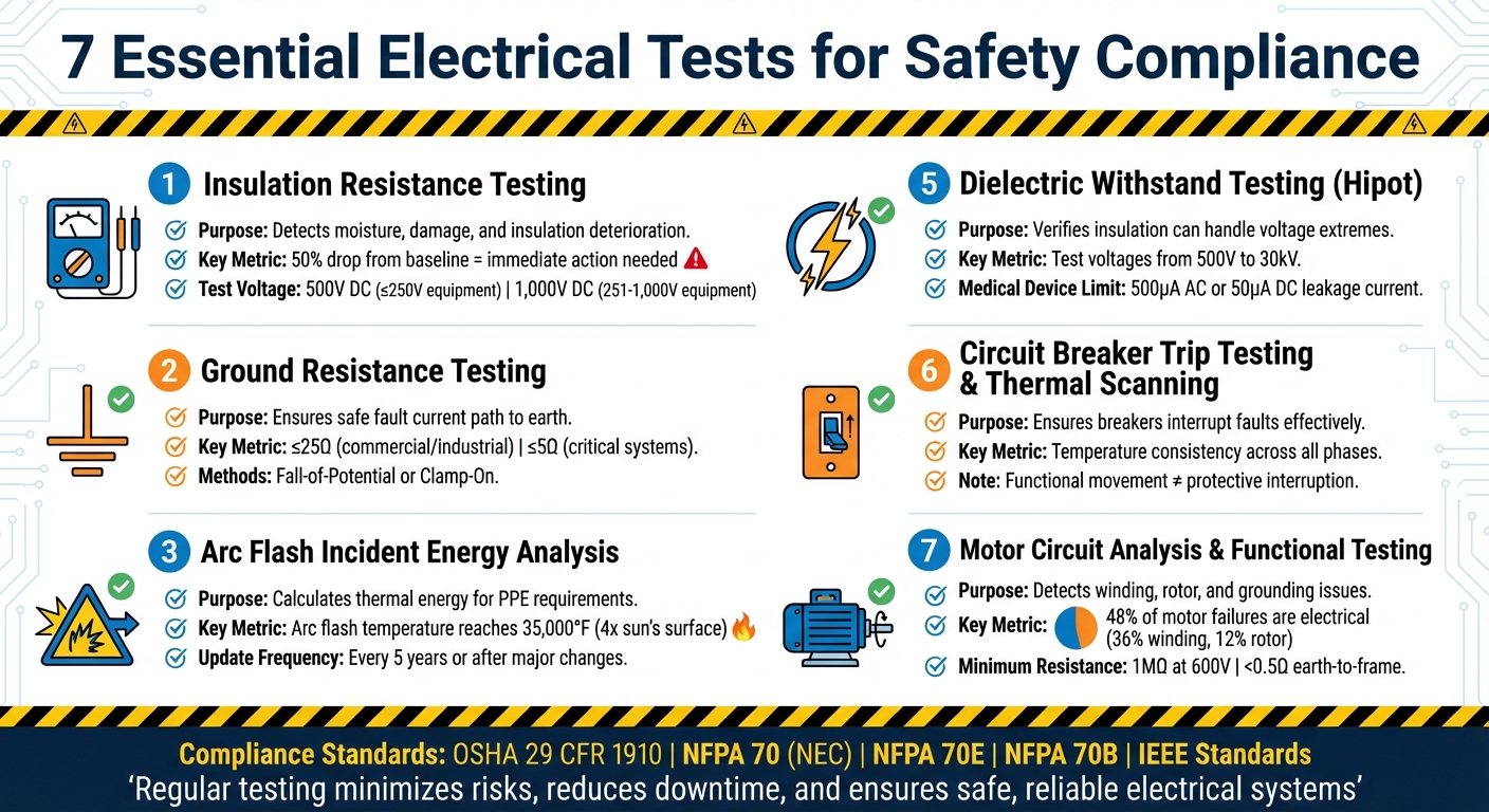
Top 7 Electrical Tests for Safety Compliance
- Insulation Resistance Testing: Detects insulation issues like moisture or damage to prevent current leakage.
- Ground Resistance Testing: Confirms grounding systems can safely channel fault currents to avoid shocks and equipment damage.
- Arc Flash Incident Energy Analysis: Calculates thermal energy from arc faults to ensure proper PPE and safety protocols.
- Thermal Imaging and Infrared Thermography: Identifies overheating components in energized systems to catch issues early.
- Dielectric Withstand Testing (Hipot): Verifies insulation can handle high voltage without leakage or failure.
- Circuit Breaker Trip Testing and Thermal Scanning: Ensures breakers interrupt faults effectively and detects thermal abnormalities.
- Motor Circuit Analysis and Functional Testing: Examines motor systems and protective devices for faults and performance issues.
These tests are critical for compliance with OSHA, NFPA 70, NFPA 70E, and other standards. Regular testing minimizes risks, reduces downtime, and ensures systems remain safe and reliable.
7 Essential Electrical Safety Tests for OSHA and NFPA Compliance
1. Insulation Resistance Testing
Purpose of the test
Insulation resistance testing is essential for meeting OSHA and NFPA requirements. It ensures that insulation effectively prevents current leakage between conductors and the ground. This test identifies problems like moisture intrusion, physical damage, or chemical deterioration in insulation, which can lead to hazards such as electrical shocks, short circuits, and even fires. For facilities with aging infrastructure, this testing becomes even more critical, as PVC insulation typically begins to break down after 20 to 30 years of use. By tracking resistance trends over time, this test helps with predictive maintenance, enabling repairs before failures occur.
Testing methodology
The process involves applying a high DC voltage to a de-energized circuit and measuring the leakage current to determine resistance in megohms (MΩ). A battery-powered or high-voltage megohmmeter is typically used for this purpose.
Key precautions before testing include:
- Confirming a zero-energy state using lockout/tagout procedures.
- Discharging any stored capacitance.
- Ensuring the test voltage aligns with the equipment's rating.
For equipment rated ≤250 V, use 500 V DC, and for equipment rated between 251 and 1,000 V, use 1,000 V DC.
Temperature plays a significant role in the accuracy of these measurements. Resistance values roughly double for every 10°C drop. To maintain consistency, record the ambient temperature and normalize readings to 40°C for accurate trend analysis. For rotating equipment, a Polarization Index (PI) test is often performed. This test compares the resistance measured at 10 minutes to the resistance at 1 minute. According to IEEE 43 guidelines, a PI below 1.0 is unsafe, while a PI above 2.0 indicates the insulation is in good condition.
Compliance with safety standards
Insulation resistance testing is a critical step for obtaining safety certifications, including the Electrical Installation Certificate (EIC) and the Electrical Installation Condition Report (EICR). It ensures compliance with standards such as IEEE 43-2013, NETA ATS/MTS, and NFPA 70B. A commonly used guideline for acceptable resistance at 40°C is (kV_rated + 1) MΩ. However, IEEE 43-2013 suggests higher thresholds, sometimes up to 5,000 MΩ, for new or recently rewound form-wound machines.
Practical relevance to safety and risk mitigation
A 50% drop from the baseline resistance is often a red flag, signaling rapid insulation degradation that requires immediate attention. Monitoring trends over time provides much more insight than one-time measurements. As the National Electrical Authority explains:
"A breaker that trips and resets may have operated under an overload condition that caused thermal damage to conductor insulation... insulation resistance testing is required to confirm the conductor is undamaged".
With an estimated 25% of homes in the UK having unsafe wiring, regular insulation resistance testing is a crucial step in minimizing electrical risks and ensuring safety in both residential and industrial settings.
sbb-itb-501186b
2. Ground Resistance Testing
Purpose of the Test
Ground resistance testing ensures that a grounding system can safely channel fault currents into the earth. This low-resistance path is essential for preventing electric shock and avoiding damage to equipment during electrical faults. The test evaluates the resistance between a grounding electrode and "true earth", confirming that the system meets design requirements and safety standards. Without proper grounding, protective devices like circuit breakers might not activate during a fault, creating serious risks for both personnel and equipment.
Testing Methodology
There are two main methods for conducting ground resistance tests, depending on the facility:
- Fall-of-Potential Method: Commonly used for new installations, this method involves placing two temporary stakes in the ground at specific distances from the grounding electrode. By measuring the voltage drop, resistance can be calculated.
- Clamp-On Method: Ideal for active commercial and industrial sites, this method allows testing without disconnecting grounding electrodes or interrupting operations.
For residential systems, a resistance below 5 ohms is generally acceptable. In industrial settings, where electrical loads are higher, even lower resistance values are often required to maintain safety. Knowing which method applies ensures compliance with safety regulations and proper system performance.
Compliance with Safety Standards
Standards like IEEE 142-2007 (Green Book) advise that most commercial and industrial grounding systems should have a resistance of 25 Ω or less, while critical systems may require 5 Ω or less. The National Electrical Code (NEC) focuses on installation and testing practices rather than prescribing specific resistance values for general installations. In the U.S., compliance is governed by NFPA 70 (NEC), along with standards from NETA and IEEE.
Practical Relevance to Safety and Risk Mitigation
Herbert Post, a Safety Compliance Expert at TRADESAFE, emphasizes the importance of grounding:
"Grounding isn't just about wiring or circuits, it's a safeguard that directs stray electrical currents safely into the earth, protecting us from shocks, equipment from damage, and workplaces from fire hazards".
Grounding tests are especially important after events like lightning strikes, which can disrupt or damage the system. Facilities with high-power machinery should consider conducting tests quarterly rather than annually. Recording initial resistance values during commissioning provides a baseline for monitoring system health over time, helping to identify degradation early. This test plays a vital role in maintaining a robust electrical safety program.
3. Arc Flash Incident Energy Analysis
Purpose of the Test
Arc flash incident energy analysis uses mathematical models to estimate the thermal energy released during an arc fault. Unlike hands-on electrical tests, this is a precise engineering simulation of your electrical system. The analysis focuses on two key safety factors: the arc flash boundary (the distance at which energy drops to 1.2 cal/cm², the threshold for second-degree burns) and the Personal Protective Equipment (PPE) required to protect workers.
This process is required under NFPA 70E Article 130.5 to safeguard workers from severe thermal energy exposure. Arc flash events can reach a staggering 35,000°F, which is about four times hotter than the sun’s surface. Without this analysis, facilities can't accurately determine the safety gear needed for electricians or define safe working distances from energized equipment. The results also guide safety protocols and future testing.
Testing Methodology
To conduct the analysis, engineers use advanced software tools like SKM Power Tools, ETAP, or EasyPower, following the IEEE 1584-2018 standard. They input critical system data, including utility fault current, transformer impedance, conductor dimensions, and overcurrent protection settings. For motors exceeding 50 HP, their fault current contributions must also be factored in.
Both maximum and minimum fault scenarios are calculated. Interestingly, lower fault currents can sometimes pose greater risks because protective devices may take longer to trip, allowing more energy to build up. Tim Cheung, CTO of Factory AI, emphasizes the importance of breaker maintenance in ensuring accurate results:
"If your breakers are not physically tested and maintained to operate within their specified clearing times, the math in your arc flash study is worthless. The label on your panel becomes a lie".
For example, if a breaker trips in 0.5 seconds instead of the expected 0.06 seconds due to poor upkeep, the incident energy can increase by around 8x.
Compliance with Safety Standards
The analysis must align with NFPA 70E for risk assessments and NFPA 70B for equipment maintenance. Notably, NFPA 70B has shifted from being a recommendation to a mandatory standard, making physical maintenance of breakers a legal requirement. Accurate calculations are critical, as they directly influence safety labels and maintenance procedures. Additionally, OSHA 29 CFR 1910.269 requires employers to provide a "reasonable estimate" of incident heat energy for workers exposed to electric arcs. NEC Article 110.16 further mandates permanent arc flash warning labels on equipment that may require energized examination.
NFPA 70E 130.5(G) specifies that the analysis must be updated after major system changes or reviewed for accuracy at least every five years. For a medium-sized manufacturing facility (around 500,000 sq. ft.), a complete study typically costs between $15,000 and $40,000, with data collection making up 40-50% of the total expense.
Practical Relevance to Safety and Risk Mitigation
The analysis highlights "Dangerous" zones where incident energy exceeds 40 cal/cm², making energized work strictly off-limits. In these cases, engineering solutions like Arc Reduction Maintenance Switches (ARMS) or Zone Selective Interlocking (ZSI) are necessary to reduce risks. High-energy zones also require strict PPE compliance and expose facilities to potential medical costs averaging $1.5 million per injury, along with fines exceeding $160,000 for OSHA violations.
To avoid delays, facilities should request utility fault current data as early as possible when preparing for a study. This process can take several weeks.
Electrical Safety - Electrical Safety Testing
4. Thermal Imaging and Infrared Thermography
Thermal imaging continues to stand out as a critical non-invasive method for evaluating electrical systems, offering real-time insights into equipment performance.
Purpose of the Test
Thermal imaging relies on infrared cameras to detect unusual heat patterns in energized electrical components. When connections loosen or components start to fail, resistance increases, generating localized heat that can be detected as infrared energy. This method pinpoints issues like faulty connections, unbalanced loads, and deteriorating insulation - all while systems remain operational. The National Fire Protection Association reports that electrical system failures, such as damaged insulation or faulty terminals, account for about 10% of fires in manufacturing facilities. Early detection through thermal imaging plays a key role in reducing equipment failures, avoiding unplanned downtime, and minimizing unnecessary energy use.
Testing Methodology
Thermographic inspections involve scanning energized equipment while it operates under load. For reliable results, systems should run at 40%–70% of their rated capacity, ensuring temperature differences are detectable. Infrared cameras are used to compare the temperature of potentially problematic components against similar components under the same load. A temperature difference (ΔT) of 15°C or more typically signals the need for immediate corrective action.
Because infrared cameras require a clear line of sight, technicians may need to open panels or use infrared windows to assess internal components like bus ducts, terminations, or switchgear. Inspections follow a structured process:
- Load Verification: Confirm the equipment is operating under appropriate load conditions.
- Emissivity Calibration: Adjust the camera for accurate readings.
- ΔT Measurement: Measure temperature differences and classify severity.
Severity levels guide responses:
- Class 1 (1°C–10°C): Monitor the situation.
- Class 2 (11°C–40°C): Repairs should be completed within 30 days.
- Class 3 (above 40°C): Immediate action is required, which may include shutting down the equipment.
Compliance with Safety Standards
Thermal imaging aligns with established safety and maintenance practices, including NFPA 70B and NFPA 70E for arc flash protection. ASTM E1934 offers additional guidance for performing infrared thermography on electrical equipment. OSHA (29 CFR 1910.335) mandates proper eye and face protection when there’s a risk of exposure to electric arcs. Inspections must be conducted by certified professionals, such as those accredited by the American Society for Nondestructive Testing or the Infraspection Institute.
Facilities with significant electrical demands should schedule annual thermographic inspections for critical systems like circuit panels, transformers, and switchgear. Immediate inspections are recommended after events like panel modifications, power surges, or the detection of a burning odor.
Practical Relevance to Safety and Risk Mitigation
Thermal imaging serves as a crucial screening tool, helping operators prioritize further testing and take corrective actions. Similar to insulation resistance testing or arc flash analysis, it identifies risks while systems remain active, avoiding the need for shutdowns. Operators should follow NFPA 70E guidelines for maintaining safe distances and wear the appropriate personal protective equipment when working near energized components.
Key targets for thermal imaging inspections include switchgear, distribution panels, transformers, motor control centers, and cable tray splice points. Immediate scans are recommended if warning signs appear, such as dimming lights during startup, unexplained spikes in power usage, or symptoms linked to aluminum wiring.
5. Dielectric Withstand Testing
Dielectric withstand testing, often called Hipot testing, is a crucial step in verifying the safety of electrical equipment. By applying high voltage, this test ensures that insulation can endure extreme conditions without failure.
Purpose of the Test
During dielectric withstand testing, voltages far exceeding normal operating levels - ranging from 500 V to 30 kV - are applied to assess insulation integrity. The goal is simple but critical: confirm that the insulation can prevent dangerous leakage currents that could lead to shocks, fires, or equipment malfunctions. As William Conklin, Technical Editor at Electricity Forum, explains:
"By exceeding the normal operating voltage, the Hipot Test can reveal hidden defects or weaknesses that might not be apparent during regular use."
This test is especially effective in identifying issues like pinholes or thin insulation spots that may not show up under normal conditions but could fail catastrophically during a power surge. For example, medical devices under IEC 60601-1 must limit patient leakage current to 500 μA AC or 50 μA DC.
Testing Methodology
The process involves applying high voltage between live parts and grounded components, such as a chassis or enclosure, while measuring leakage current. Three key parameters guide the test:
- Ramp Time: How quickly the voltage increases.
- Dwell Time: The time the voltage is held at its peak (typically 1 to 60 seconds).
- Shutdown Threshold: The maximum allowable leakage current before the test fails.
Specialized Hipot testers, like the Vitrek V7X or 95X Series, measure leakage current with extreme precision - down to picoamps. A device passes if its leakage current stays below the set threshold and no electrical arc occurs during the dwell period. AC testing accounts for the effects of alternating current cycles, while DC testing focuses on steady-state current flow. After DC testing, any residual voltage must be discharged immediately to avoid potential shocks. These procedures adhere to stringent industry requirements.
Compliance with Safety Standards
Dielectric withstand testing is a key requirement in various safety standards. For example:
- UL 60950: IT and office equipment
- IEC 60601: Medical devices
- IEC 61010: Laboratory equipment
- ISO 6469: Electric vehicles
- IEEE Standard 400: Power cable systems
- ANSI/NETA ATS: Electrical power equipment testing
Medical devices often face the strictest requirements. For instance, the 2 x MOPP (Means of Patient Protection) standard demands an isolation voltage of 4,000 Vac and an 8 mm creepage distance.
Practical Relevance to Safety and Risk Mitigation
This test is performed offline, eliminating risks like shock or arc flashes during the process. Accurate readings depend on regular calibration of Hipot testers, while features like built-in arc detection help pinpoint insulation breakdowns that might otherwise go unnoticed. To enhance safety, technicians should follow lockout/tagout procedures and wear insulated gloves and safety glasses.
6. Circuit Breaker Trip Testing and Thermal Scanning
After completing insulation and ground resistance tests, breaker trip testing and thermal scanning add another layer of safety assurance. These tests evaluate whether breakers can handle fault conditions effectively, cutting off dangerous energy flows before they lead to fires or equipment damage.
Purpose of the Test
There’s a key difference between a breaker’s basic functionality and its ability to provide protection. A breaker might open and close smoothly during routine checks but still fail to interrupt current quickly enough during an actual fault. William Conklin, Associate Editor at Electricity Forum, highlights this common misunderstanding:
"Functional movement and protective interruption are not the same thing, and confusing them is one of the most persistent errors in breaker evaluation."
Thermal scanning complements trip testing by identifying excessive heat caused by loose connections or overloads. Infrared cameras detect abnormal temperature variations, allowing technicians to catch issues before they escalate. In three-phase systems, temperatures across all phases should be consistent; deviations of more than a few degrees may signal trouble. Aaron Dahlen, Senior Applications Engineer at DigiKey, explains:
"The thermographic inspection is especially useful for detecting loose electrical connections or overloaded circuits."
These insights form the foundation for the testing methods outlined below.
Testing Methodology
Trip Testing: This involves simulating fault conditions to measure how quickly a breaker interrupts current. The goal is to ensure the breaker responds fast enough to prevent energy from spreading downstream. Tests must consider system-level factors, such as short circuit analysis, coordination with upstream devices, and changes in fault current levels since installation.
Thermal Scanning: For this test, equipment must be energized and operating under normal conditions. Modern thermal imagers capture both infrared and visible images, helping pinpoint issues while avoiding false readings from reflective surfaces like bus bars. Technicians establish baseline thermal profiles to monitor component performance over time. Importantly, Lockout/Tagout (LOTO) protocols must be followed during both energized and de-energized inspections.
Once these tests confirm breaker performance and thermal stability, compliance with OSHA and PPE standards is reviewed.
Compliance with Safety Standards
Trip testing supports OSHA requirements by ensuring equipment maintenance and identifying arc flash hazards. These protocols, combined with LOTO procedures and proper PPE usage, contribute to a comprehensive safety strategy. Interpreting results in the context of the entire electrical system is crucial, as recurring tripping or overheating often points to broader issues like wiring degradation or coordination failures.
Practical Relevance to Safety and Risk Mitigation
These tests are critical for identifying breakers that can no longer interrupt fault currents within safe limits. As Conklin explains:
"A breaker that 'tests fine' in isolation may already be operating beyond its original protective margin."
Breakers that have experienced significant faults, prolonged overheating, or repeated mechanical stress should be replaced rather than retested, as further testing might give a false sense of security. Thermal scanning also helps maintenance teams prioritize repairs by categorizing issues from urgent fixes to less critical concerns. This approach prevents catastrophic failures and ensures resources are allocated effectively.
7. Motor Circuit Analysis and Functional Testing
Once breaker trip testing is complete, motor circuit analysis becomes the next crucial step in electrical safety testing. This process focuses on examining critical motor components and their associated switchgear - elements that are particularly prone to failure. Like earlier tests, motor circuit analysis is essential for identifying potential electrical hazards and ensuring the system remains safe and reliable, all while meeting established safety standards. According to IEC 61010, polyphase motors and their switchgear are classified under Measurement Category III (CAT III). These tests confirm that motors, protective devices, and circuits can operate safely under both normal conditions and faults.
Purpose of the Test
The main objective of motor circuit analysis is to uncover issues like insulation breakdown, defective wiring, or poor grounding before they lead to more severe problems such as electrical shocks, fires, or explosions. Data shows that electrical faults cause nearly half of all motor failures - 36% due to winding problems and 12% from rotor issues. Functional testing complements this by ensuring that protective devices, such as circuit breakers and RCDs, trip at the appropriate current levels to prevent electrocution. Together, these tests address motor-specific risks and verify the functionality of protective mechanisms.
As Fluke highlights:
"A well-built multimeter will protect against electrocution and arc explosion. It will carry a Measurement Category III rating... [for] switchgear and polyphase motors."
Testing Methodology
Motor testing is divided into two categories: offline and online tests.
- Offline tests include insulation resistance, winding resistance, and surge testing, with all readings adjusted for temperature (e.g., 40°C for insulation and 20°C for winding).
- Online tests measure voltage, current, and mechanical performance under load to detect power quality issues.
All measurements should be conducted using certified instruments (UL, CSA, TÜV) with appropriate CAT ratings.
For functional testing of ground fault devices, a calibrated leakage current - such as 5 mA for Class A GFCI devices - should be applied. Relying solely on built-in test buttons is not sufficient. Thomas Smith, Product Compliance Manager at Fluke, emphasizes:
"We test at least one level beyond the standard. Additionally, our work in foreseeable misuse has led to the development of new standard requirements."
Compliance with Safety Standards
This testing adheres to stringent standards, such as IEEE 43-2013 for insulation resistance, NFPA 70B for electrical equipment maintenance, and NETA ATS/MTS for acceptance and maintenance testing. These standards ensure that the procedures align with OSHA workplace safety protocols and international IEC requirements. Keeping detailed records of all tests is critical for regulatory audits and maintaining long-term safety compliance.
Practical Relevance to Safety and Risk Mitigation
Never assume a circuit is safe just because a breaker resets after tripping. The National Electrical Authority cautions:
"A breaker that trips and resets may have operated under an overload condition that caused thermal damage to conductor insulation without producing a sustained fault. Resetting does not restore insulation integrity."
After a trip event, insulation resistance testing can confirm whether the conductors have been compromised. For systems rated at 600V, a minimum insulation resistance of 1 MΩ is typically required, while the resistance between earth and the motor frame should be under 0.5 Ω to ensure proper fault clearing. Additionally, temperature differences exceeding 15°C in motor control centers signal the need for immediate corrective action. Regular predictive maintenance using these tests can significantly reduce the likelihood of major failures, keeping industrial operations safe and efficient.
Conclusion
The seven electrical tests covered in this guide are essential for ensuring safety compliance. Each test plays a critical role in identifying potential hazards like injuries, fires, or system outages. As the National Electrical Authority explains:
"Electrical system testing and diagnostic methods form the structured technical foundation for identifying faults, verifying performance, and confirming code compliance across residential, commercial, and industrial installations."
These tests are required by standards such as NFPA 70 (National Electrical Code), NFPA 70E (Electrical Safety in the Workplace), and OSHA 29 CFR 1910 Subpart S. Beyond meeting these regulations, they provide crucial protection for workers by establishing arc flash boundaries, ensuring ground fault devices function properly, and identifying thermal issues before they lead to serious failures. Regular testing not only improves safety but also ensures systems remain dependable over time.
Understanding the difference between acceptance and maintenance testing is key. For new installations, the NETA Acceptance Testing Specifications (ATS) help meet the requirements of the Authority Having Jurisdiction before systems are energized. On the other hand, Maintenance Testing Specifications (MTS) are designed for ongoing systems, helping track wear and detect issues as equipment ages. Both types of testing rely on calibrated tools and thorough documentation, which are essential for future audits and comparisons.
Carrying out these tests requires high-quality tools and dependable components. Whether you're looking for insulation resistance testers (Megohmmeters), ground continuity meters, infrared thermography tools, or even circuit breakers and transformers, Electrical Trader provides a one-stop shop for both new and used electrical testing equipment. This makes it easier for electricians and facility managers to maintain safety standards while accessing reliable resources.
Bottom line: Regular electrical testing doesn't just meet regulatory requirements - it prevents failures, extends equipment life, and protects workers. Monitoring electrical systems consistently allows for early issue detection and sustained safety compliance. By following the testing protocols outlined here, you're ensuring not only code compliance but also long-term reliability and workplace safety. These practices create a strong foundation for safe and effective power distribution systems.
FAQs
How often should these electrical safety tests be done?
Electrical safety tests, including insulation resistance and ground fault testing, should align with the specific requirements of the installation. For environments considered high-risk, these tests are typically needed every year. In contrast, other properties might only require testing intervals ranging from 1 to 10 years. Always ensure compliance with the appropriate safety standards and guidelines relevant to your property's type and usage.
Which tests can be performed while equipment stays energized?
Testing energized equipment is crucial to ensure safety and compliance without interrupting operations. Common tests include:
- Insulation Resistance Testing: Evaluates the integrity of electrical insulation to prevent potential failures or hazards.
- Ground/Earth Testing: Verifies proper grounding to ensure electrical safety and fault protection.
- Polarity Testing: Confirms correct wiring connections, reducing risks of malfunction.
- Loop Impedance Testing: Assesses the effectiveness of the circuit's protective devices by measuring impedance.
- RCD Testing: Checks the functionality of Residual Current Devices (RCDs) to detect and respond to leakage currents.
These tests allow for thorough safety checks while keeping equipment operational.
When do I need to update an arc flash study?
An arc flash study needs updating every five years to stay aligned with safety standards and ensure workplace safety. These updates are crucial because they account for changes such as new equipment, modified system configurations, or updated regulations that might affect the study's accuracy.


