
Electrical Commissioning: Best Practices
Electrical commissioning ensures your electrical systems are safe, reliable, and perform as intended. With 70% of early power system failures linked to design, installation, or startup issues, commissioning identifies and resolves problems before they cause costly downtime or safety risks.
Key Takeaways:
- Planning Early: Involve experts during the design phase to prevent errors and save costs.
- Thorough Testing: Pre-commissioning tests like insulation resistance and control loop checks catch issues before energization.
- Safety First: Follow lockout/tagout (LOTO) protocols, complete arc flash studies, and verify grounding resistance.
- Documentation: Maintain detailed records for compliance and future maintenance.
This step-by-step process - from planning and testing to energization and documentation - ensures systems meet standards like NEC, NFPA, and NETA while supporting long-term reliability.
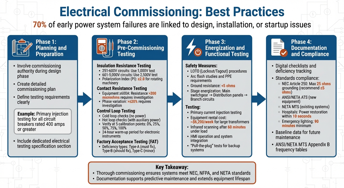
4-Phase Electrical Commissioning Process: From Planning to Documentation
Testing and Commissioning of Electrical Equipment
sbb-itb-501186b
Planning and Preparation
Strong planning and preparation are the backbone of any successful electrical commissioning process. Think of the commissioning plan as a detailed roadmap - it lays out the goals, processes, and responsibilities needed to keep everything on track. Without this clear foundation, the process can quickly spiral into chaos, leading to missed tests and expensive delays. This early groundwork is what ensures thorough design reviews and accurate testing procedures later on.
The best time to start planning? During the design phase. John Hebert, Senior Electrical Engineer, emphasizes this point:
"The design review focuses on test requirements, sequences of operation, accessibility for maintenance and operations, and essential system equipment design".
Getting the commissioning authority involved early is key. It allows them to identify design or specification gaps well before equipment is purchased or installed - when fixes are much cheaper and easier to implement. Early design reviews can uncover critical equipment and operational details that might otherwise be overlooked. For example, during the submittal stage, specifics like custom load shedding sequences for paralleling switchgear often come to light. Catching these details early prevents costly on-site errors, such as receiving equipment that doesn’t meet project specifications.
Clear and precise testing requirements are another cornerstone of successful preparation. Ambiguity in project specifications can lead to confusion and delays. Instead, testing requirements should be written with absolute clarity. For instance, specifying "primary injection testing for all circuit breakers rated 400 amps or greater" removes any guesswork. This level of detail not only ensures that everyone knows what needs to be tested but also helps contractors align their testing schedules with the project timeline, avoiding unnecessary cost overruns.
A great way to streamline this process is by including a dedicated electrical testing specification section in the project documents. This section consolidates all testing requirements into one easy-to-reference location. As one commissioning professional puts it:
"A dedicated electrical testing specification section provides a concise listing of all electrical testing requirements in a single location".
This method ensures that no testing requirements get lost during the handoff from design to construction, keeping the entire process running smoothly.
Pre-Commissioning Testing
Pre-commissioning tests are the last line of defense before powering up a system. These tests are designed to catch potential issues that could lead to equipment failure, safety risks, or costly downtime. As Paul Turner from the Commissioning & Assurance Academy puts it:
"Skipping tests in the process rarely results in saved time. A properly planned and executed commissioning sequence will include all pre-commissioning and commissioning tests required to demonstrate a properly functioning system".
With safety as the top priority, the next step is to assess key physical parameters.
Test Insulation Resistance and Contact Resistance
Insulation resistance testing, often carried out with a megger, checks the integrity of the dielectric by applying voltage. This test can uncover problems caused by factors like moisture, dirt, corrosion, vibration, or aging. For example, leftover temporary brackets on live components can lead to immediate failure if undetected. John Olobri, an Electrical and Industrial Engineer at AEMC Instruments, emphasizes:
"Insulation resistance testing helps ensure personnel safety and optimal operation of equipment. It also helps evaluate the quality and level of repairs that may be required before equipment is put back into operation".
For circuits between 251–600V, use a 1,000V test. For circuits between 601–5,000V, a 2,500V test is recommended. Record the temperature and adjust readings to 68°F (20°C). When testing large rotating machinery, the Polarization Index (PI) - the ratio of the 10-minute reading to the 1-minute reading - should generally be 2.0 or above.
Contact resistance testing, on the other hand, identifies loose connections, broken strands, and excessive resistance in components like tap changers, breakers, and contactors. For equipment rated at 600A or higher, resistance levels exceeding 200 microohms or variations greater than ±20% between phases require further investigation. These tests are essential for preventing overheating or arc faults caused by poor connections. To ensure accurate results, circuit breakers should be closed and locked during testing.
Once the physical integrity of electrical components is verified, attention shifts to control systems and communication pathways.
Verify Control Loops and Communication Signals
Control loop testing ensures that all interconnected instrumentation components are functioning properly and ready for plant commissioning. This process involves two phases: cold loop checks and hot loop checks. Cold loop checks, performed without power, confirm point-to-point wiring between terminal blocks. Hot loop checks, conducted after applying auxiliary power, validate the entire signal path from the Human-Machine Interface (HMI) to the end device. This includes calibration, scaling (e.g., 4–20 mA signals), and alarm setpoints.
During hot loop checks, field devices must communicate correctly with the PLC or HMI using protocols like MODBUS or PROFIBUS. Instruments are typically verified at five calibration points - 0%, 25%, 50%, 75%, and 100% - for both rising and falling signals to ensure they meet manufacturer tolerances. For electronic instruments, a 24-hour warm-up period is recommended before performing calibration tests. Since the plant process is not operational during pre-commissioning, temporary jumpers are often used to simulate digital I/O signals or physically stimulate analog devices, such as moving a level sensor. Keeping a detailed log of these temporary jumpers is critical, as Paul Turner notes that forgotten jumpers can jeopardize plant startup. Loop testing usually requires two technicians - one working in the field and the other in the control room, coordinating via radio.
After verifying field operations, factory tests help identify issues before equipment reaches the site.
Complete Factory Acceptance Testing
Factory Acceptance Testing (FAT) is conducted at the manufacturer’s facility to detect and resolve problems before equipment is shipped. Engineers use this opportunity to simulate operations, such as load transfers and fault conditions, in a controlled environment, addressing issues when they’re easiest and most cost-effective to fix.
One advantage of FAT is the ability to compare results later. Site Acceptance Testing (SAT) results should always be compared with FAT data to identify whether equipment was damaged or misaligned during transport. For manufacturers in remote or international locations, virtual factory witness testing via video conferencing has become a popular alternative to in-person visits.
Issues identified during pre-commissioning are categorized into three types: Type-A (must be resolved before proceeding), Type-B (should be fixed before handover), and Type-C (minor or cosmetic issues). Type-A deficiencies, which involve functional or safety problems, must be addressed before moving forward with commissioning.
Energization and Functional Testing
Once pre-commissioning tests are complete and any issues have been resolved, it's time to bring the system to life. This phase involves energizing the system while adhering to strict safety protocols. These precautions are the practical application of all the planning and testing that came before. Building on the success of pre-commissioning, energization ensures the system is safe to operate and fully integrated.
Confirm Safety Measures Before Energization
Before powering up, lockout/tagout (LOTO) procedures are essential. This involves locking power switches in the "off" position and tagging them to prevent accidental activation while work is ongoing. Arc flash studies must also be completed to determine the necessary Personal Protective Equipment (PPE), such as arc-rated clothing, face shields, and insulated gloves. Ground resistance should be checked and typically needs to measure under 5 ohms to ensure safety for both personnel and equipment.
A thorough visual inspection is critical - verify that equipment is mounted correctly, cables are securely routed, and labeling aligns with NFPA 70 standards. Before power is applied, make sure all circuits, switches, and transfer switches are in the "off" position. Energization should be staged: start with the main switchgear, then move on to distribution panels and branch circuits. Use a phase rotation meter to confirm the correct phase sequence before running three-phase motors, as incorrect sequencing could cause motors to spin backward, leading to mechanical damage.
Perform Primary Current Injection and Overcurrent Device Tests
Primary injection testing is a critical step to ensure the entire protection system functions as intended. Unlike secondary injection, which only checks relay logic, primary injection tests the entire circuit. This includes current transformer (CT) windings, relay coils, trip and alarm circuits, and all associated wiring. This process can uncover issues like wiring errors or incorrect CT polarity, which might otherwise lead to false tripping or failure during a fault.
Modern test equipment can inject up to 200A per unit, while older portable transformers deliver outputs like 10V and 1,000A. For large power transformers, a 1,000 kVA, 480V generator and a 1,000 kVA step-up transformer may be necessary, with weekly rental costs in the U.S. averaging $6,200. This testing ensures that circuit breakers trip within their specified parameters and that relays activate at the correct current levels. Edvard Csanyi, Founder of EEP, stresses its importance:
"Primary injection testing is, however, the only way to prove correct installation and operation of the whole of a protection scheme".
After the system has been operating under load for at least 60 minutes, infrared cameras should be used to check for loose connections or "hot spots".
Test System Integration and HMI Operation
Once the system is successfully energized, integrated testing ensures all subsystems communicate and work together as designed. Integrated Systems Testing (IST) involves verifying that every component functions as part of a cohesive whole. For example, "pull-the-plug" tests simulate a total power loss by cutting utility power to see if the system - including generators, UPS units, and multiple power paths - responds correctly.
Control signal integrity must also be confirmed between interconnected systems like HVAC, fire alarms, and automation. Hardware and software interlocks should be tested to ensure all responses follow the intended logical sequence. The Human-Machine Interface (HMI) should display real-time data, including current, voltage, and alarm logs from systems like the Building Management System (BMS) or SCADA.
All alarm points - such as emergency stop and reset sequences - must be tested to confirm they trigger the appropriate visual and audible alerts on the HMI and annunciator panels. Finally, remote communication protocols like BACnet or Modbus need to be verified to ensure the HMI can interact with the facility's maintenance system. Brent Kooiman, P.E., highlights the importance of this step:
"Power system commissioning is a systematic approach that makes sure... metering and communications are working and viewable".
Documentation and Compliance
After successfully completing energization and testing, maintaining thorough documentation and adhering to compliance standards are crucial for ensuring the long-term reliability of systems. Recording all commissioning results accurately serves as proof of proper installation and compliance with safety regulations. These records not only support inspections but also provide a clear roadmap for future maintenance efforts.
Develop Project Checklists and Track Deficiencies
Digital checklists are an efficient way to monitor tests and track deficiencies. Unlike manual record-keeping, digital systems reduce the risk of errors. Paul Turner from the Commissioning & Assurance Academy emphasizes this advantage:
"A CMS system significantly helps track and close all the deficiencies on a project to ensure that none of the small details are missed and become bigger problems later in the project".
By using digital systems and real-time deficiency logs, responsibilities and deadlines can be clearly assigned, helping to avoid delays that could disrupt project timelines. Each deficiency should be assigned to a specific individual, with deadlines tied to project milestones. For equipment that is repetitive, like multiple pumps or breakers, standardized templates ensure data is consistent and easy to search. Additionally, requesting equipment settings for Automatic Transfer Switches well ahead of functional testing allows time for necessary calculations and adjustments in the field.
Follow NEC and NERC Standards
Meeting regulatory standards is essential for both legal compliance and operational safety. Key documents such as the Owner's Project Requirements (OPR), Basis of Design (BOD), and Design Intent Document (DID) establish the performance criteria for the project. John Hebert, Senior Electrical Engineer, explains the importance of the DID:
"The Design Intent Document (DID) will quantitatively define the performance and operational requirements for the commissioned systems. These performance requirements will be the acceptance criteria against which the systems will be judged".
Testing reports must align with ANSI/NETA ATS standards for new equipment and NETA MTS for existing systems. NEC Article 250 requires grounding resistance tests to show a maximum of 25 ohms, though IEEE and NFPA recommend aiming for 5 ohms or less for enhanced safety. For hospitals and other facilities with life safety systems, the NEC mandates that power restoration to essential loads must occur within 10 seconds of a utility outage, and emergency lighting systems must operate for at least 90 minutes. Additionally, permanent equipment labels should match design drawings to prevent discrepancies.
Plan for Future Re-Commissioning and Maintenance
The initial commissioning process creates baseline data that serves as a benchmark for all future testing. Joel Gilley, Director of Commissioning Services at Electrical Reliability Services, Inc., highlights this point:
"The documentation and baseline data generated during commissioning and acceptance testing provide the reference point against which all future testing is measured".
Maintenance intervals should be determined using ANSI/NETA MTS Appendix B frequency tables, which take system criticality into account. Tools like PowerDB can store this data electronically, enabling long-term asset management and comparison across facilities. Annual visual inspections and thermal imaging are recommended, particularly when equipment is operating under peak load conditions. A well-structured maintenance plan promotes predictive maintenance, lowers overall ownership costs, and extends the lifespan of essential infrastructure.
Thorough documentation ties the initial commissioning phase to ongoing performance and safety, ensuring systems remain reliable and compliant over time.
Conclusion
Electrical commissioning goes beyond a simple final inspection - it's a structured process that ensures every component aligns with project requirements, from the design phase to final handover. Studies show that about 70% of early power system failures stem from issues in design, installation, or startup. This makes thorough commissioning critical for minimizing downtime and preventing safety risks.
The earlier phases - planning, testing, and energization - lay the groundwork for reliable system performance. Involving commissioning experts during the pre-design stage can help identify potential issues before construction even begins. This proactive approach cuts down on costly rework and avoids delays. Testing methods like primary current injection and integrated systems testing verify that protective devices and controls perform as intended under actual operating conditions.
Additionally, the documentation created during the commissioning process serves as a vital reference for future maintenance and testing. This data supports predictive maintenance strategies, helps plan outages efficiently, and guides decisions throughout the equipment's lifecycle. Following standards set by organizations like NETA, NEC, and NERC ensures compliance with legal and safety requirements. These standards also provide clear testing criteria and establish maintenance schedules based on the criticality of the equipment.
FAQs
Who should lead electrical commissioning?
Electrical commissioning is typically overseen by a commissioning authority (CxA) or a commissioning professional (CxP). These experts collaborate with the owner, design team, and construction team to ensure that all systems function as intended and meet the required performance goals.
What tests are required before energizing?
Before turning on electrical systems, a series of crucial tests must be performed to ensure they are safe, reliable, and meet required standards. These tests include insulation resistance checks for both control and power circuits, cable and grounding evaluations, and lightning protection system assessments.
For transformers, pre-commissioning involves visual inspections, oil quality analysis, and checks for winding resistance and turns ratio. Additionally, functional tests - like verifying system performance and ensuring protective devices work correctly - are essential. These steps help spot potential problems early and guarantee the system operates safely and according to regulations.
How do I prove code compliance after commissioning?
To confirm compliance with codes after commissioning, it's crucial to outline detailed commissioning requirements in the construction documents. These should cover aspects like the scope of testing, assigned roles, schedules, and processes for managing issues. Additionally, keep thorough records, including functional test results and Certificates of Acceptance, to show that all standards have been met. This documentation is key to verifying that the electrical systems align with safety and code requirements.


