
Core and Coil Inspection Standards Explained
Transformers are critical to power systems, and their reliability hinges on regular core and coil inspections. These inspections combine visual checks for physical damage and electrical tests to assess insulation, resistance, and overall performance. Key points to remember:
- Visual Inspections: Detect damage like rust, cracks, or leaks that can compromise performance.
- Electrical Testing: Includes insulation resistance, winding resistance, and turns ratio tests to identify issues like short circuits or core damage.
- Inspection Frequency: Annual visual checks, with electrical tests every 3–5 years, or more frequently for high-stress transformers.
- Standards Compliance: Follow IEEE and IEC guidelines to ensure safety and efficiency, such as maintaining turns ratio deviations within ±0.5% and short-circuit impedance changes under 3%.
Routine inspections prevent failures, reduce downtime, and extend transformer lifespan. Detailed records help track trends, optimize maintenance schedules, and ensure compliance with industry standards.
The Art of Power Transformer Manufacturing How to Inspect Core and Coils
sbb-itb-501186b
Why Core and Coil Inspections Matter
Core and coil inspections play a critical role in preventing transformer failures that could lead to expensive downtime. These inspections uncover issues that standard electrical testing might overlook, such as core displacement, shorted laminations, and core saturation. These problems can result in excessive heating and energy losses, jeopardizing transformer efficiency and reliability. As John Roberts, a Professional Electrical Testing Expert, notes:
"The transformer core ensures the efficient transfer of electrical energy through magnetic coupling... if the core becomes damaged... it can severely impact transformer performance and even lead to costly failures".
Damage during shipping or installation, such as cracked bushings or dented cooling fins, can compromise both cooling efficiency and structural integrity. Visual inspections help identify problems like white film caused by sun exposure, peeling paint, and rust. These surface issues can create pinholes, allowing moisture and oxygen to penetrate the tank and cause further damage. Additionally, leakage current tests on coil insulation can detect high readings that signal potential shorts, which could lead to catastrophic coil failure.
Winding resistance tests are another critical tool, as they reveal increased resistance levels that can generate heat and damage the wire over time. Core testing, on the other hand, identifies magnetic imperfections and lamination issues that increase no-load losses, reducing overall efficiency. For instance, a transformer core with insulation resistance above 200 megaohms is considered in good condition, while a grounding lead current exceeding 1 ampere points to a metal grounding fault.
When to Conduct Inspections
Inspections should start as soon as the transformer is received, using impact recorder data to check for manufacturing quality and shipping damage. Before the unit is energized for the first time, both electrical and visual tests ensure it’s ready for operation.
Routine maintenance typically follows a set schedule. Visual inspections are conducted annually, while electrical testing occurs every 3 to 5 years for most utility companies. However, critical units, such as generator step-up or furnace transformers, may require more frequent checks - up to four times a year in some cases. Inspections are also essential after specific events, like when a unit trips offline, is relocated, removed from storage, or undergoes repairs. Conducting timely inspections after such events is essential to ensure the transformer remains in optimal working condition.
Benefits of Regular Inspections
The benefits of regular inspections go far beyond just preventing failures. Early defect detection reduces unplanned downtime and enhances safety by identifying risks like insulation degradation, which could lead to short circuits or fires.
Keeping detailed inspection records not only helps with regulatory compliance but also simplifies maintenance. Adhering to IEEE standards - such as maintaining turns ratio deviations within ±0.5% and short circuit impedance changes below 3% - is easier with proper documentation. Establishing baseline data during commissioning creates a "birth certificate" for the transformer, allowing for better tracking of degradation trends over time. Monitoring tools like pressure/vacuum gauges also offer early warnings; for example, a consistent "0" reading could indicate a leak that needs immediate attention. Ultimately, thorough inspections and documentation help extend the transformer’s lifespan and improve return on investment. These advantages set the stage for more detailed criteria and best practices in the next section.
Core and Coil Inspection Criteria
Transformer Core and Coil Electrical Testing Standards and Acceptance Criteria
Thorough inspections are critical for identifying potential transformer issues before they escalate. While earlier sections discussed the importance of inspections, this part dives into the specific parameters and techniques required to ensure transformers function reliably and efficiently.
Visual and Structural Checks
Physical inspections often reveal damage that electrical tests might miss. For instance, core laminations should be scrutinized for cracks, corrosion, or deformations. These issues can disrupt magnetic flux and lead to energy losses. Problems like lamination faults, shorted turns, or loose core clamps may cause vibrations or circulating currents, gradually reducing performance.
When it comes to coil and winding assessments, signs like coil displacement or deformation often indicate power surges or mechanical strain. Abrasions on insulation and winding deformation suggest stress, while thermal damage is evident in darker insulation, cracking resin, or delamination in cast-coil designs. Overheating can often be spotted by comparing insulation color - darker areas at the top of the coil signal excessive heat, as hot air rises. Watch for "tracking" (carbon trails), surface arcing, or carbonization on insulation, all of which point to electrical stress.
External components also demand attention. Paint and coatings should be checked for issues like chalking, cracking, peeling, or rust, which can lead to pinholes. Inspect bushings and insulators for cracks, chips, discoloration, or dirt buildup. Mechanical checks should include loose or oxidized connections, worn anti-vibration pads, and bulging tank covers. Cooling systems, such as fins and radiators, should be checked for dents or leaks at flanges and welds.
A pressure/vacuum gauge reading of "0" is a red flag, even if no oil is visible, as it indicates the tank is no longer sealed. Acoustic assessments can also provide clues: loud buzzing or humming suggests core saturation or magnetic vibration, while crackling or popping may point to partial discharge or moisture in the insulation. As Jon Bucciarelli, President of SDMyers, puts it:
"Visual inspections, perhaps easier to perform as they do not require an outage, are now mandated to be supplemented with regular dielectric liquid and electrical testing".
Electrical Testing Standards
Electrical testing ensures transformers meet performance and safety benchmarks. Insulation resistance testing, for example, evaluates the insulation's ability to resist heat, moisture, and stress. For transformers rated at 600 volts or less, a minimum insulation resistance of 500 megohms at 1,000 VDC is required. To avoid moisture forming on insulation surfaces, ensure the transformer temperature is above the dew point before testing.
Winding resistance tests identify loose connections, faulty tap changers, or broken conductor strands. Results should fall within 5% variance between phases. To prevent residual magnetism from interfering, conduct magnetizing/excitation current tests before DC winding resistance tests and demagnetize the core afterward.
Transformer turns ratio (TTR) testing confirms the winding ratio between primary and secondary windings. Variances of up to ±0.5% are acceptable per IEEE standards. Excitation and no-load loss tests evaluate magnetic flux in the core; abnormal current levels can signal shorted turns, core damage, or faulty tap changers. Current readings between similar single-phase units should not vary by more than 10%.
Impedance voltage and load loss measurements gauge construction quality and mechanical integrity. Short-circuit impedance should align within ±3% of the nameplate value. Partial discharge (PD) testing helps detect early insulation failures, while Frequency Response Analysis (FRA) identifies winding movement or core deformation caused by short circuits or transport.
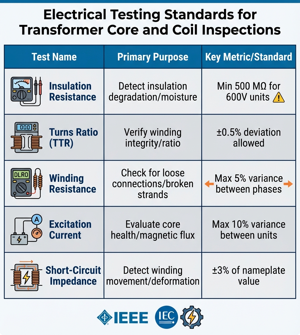
| Test Name | Primary Purpose | Key Metric/Standard |
|---|---|---|
| Insulation Resistance | Detect insulation degradation/moisture | Min 500 MΩ for 600V units |
| Turns Ratio (TTR) | Verify winding integrity/ratio | ±0.5% deviation allowed |
| Winding Resistance | Check for loose connections/broken strands | Max 5% variance between phases |
| Excitation Current | Evaluate core health/magnetic flux | Max 10% variance between units |
| Short-Circuit Impedance | Detect winding movement/deformation | ±3% of nameplate value |
Insulation and Barrier Assessments
The condition of insulation is directly tied to transformer safety and lifespan. Moisture levels are a critical factor, as moisture accelerates aging. For large units, drying the insulation is recommended if moisture levels are high, aiming to reduce residual moisture to less than 1% using low-frequency heating equipment. As Edvard Csanyi, an Electrical Engineer at EEP, explains:
"Moisture in insulation is one of the dominant ageing accelerators. It is recommended to dry the insulation when the moisture exceeds a certain level".
Visual and physical checks involve inspecting porcelain bushings for cracks or chips, ensuring gaskets remain elastic, and checking for leaks that might allow moisture or oxygen to enter. Cleaning bushings with methylated spirits or evaporative agents can remove contaminants that compromise dielectric strength. For ventilated dry-type units, use a vacuum cleaner for horizontal surfaces and dry compressed air or nitrogen (max 3 bar) for cooling ducts to avoid dust-related insulation tracking.
For oil-immersed transformers, oil quality analysis is vital. Tests like Dielectric Breakdown Voltage (BDV), Dissolved Gas Analysis (DGA), and Karl Fischer titration measure water content and assess insulation health. During insulation resistance testing, capacitance changes should not exceed 10% compared to previous records. Avoid sampling oil or performing insulation checks while the transformer is under vacuum, as this can introduce air bubbles and damage windings. Thermal imaging with infrared cameras can pinpoint hotspots caused by insulation degradation, winding shorts, or core issues.
These inspection criteria lay the groundwork for aligning with industry expectations and ensuring reliable transformer performance.
Industry Standards and Compliance
Ensuring the integrity of transformer cores and coils hinges on adhering to established industry standards. Inspections play a critical role in confirming that equipment meets essential benchmarks for safety, reliability, and global compatibility.
IEEE and IEC Standards

In North America, IEEE standards guide transformer testing, while IEC standards are widely accepted across more than 80 countries. For liquid-immersed transformers, IEEE C57.12.90-2021 outlines procedures for resistance, ratio, no-load loss, excitation, impedance, and dielectric testing. Meanwhile, IEEE C57.12.00 defines general electrical and mechanical requirements, including strict loss tolerances - no-load losses must not exceed 10%, and total losses must remain under 6%.
For dry-type transformers, IEEE C57.12.91-2020 provides a comprehensive test code for distribution and power transformers operating above 600 V. This standard also includes methods for converting test results between 60 Hz and 50 Hz, which is essential for equipment used in international markets. IEEE C57.12.60-2020 focuses on testing insulation systems' thermal performance, ensuring that solid-cast and resin-encapsulated designs can handle their rated temperature classifications. Additionally, IEEE C57.12.58-2017 addresses transient voltage analysis to measure winding response to impulse waveforms.
On the global stage, IEC 60076-3 governs insulation levels and dielectric testing, while IEC 60076-2 specifies temperature rise limits to prevent premature insulation degradation. IEEE standards tend to employ conservative safety margins, whereas IEC standards emphasize precision. A real-world example illustrates this distinction: in July 2025, a 132 kV transformer project in South America faced a failure during impulse testing. The IEC-compliant unit, designed with a lower Basic Insulation Level (BIL), was incompatible with the IEEE-based grid. The resulting redesign cost $75,000 and caused a 12-week delay until a unit meeting IEEE C57.12.00 standards could be delivered.
| Standard | Transformer Type | Primary Focus |
|---|---|---|
| IEEE C57.12.00 | Liquid-Immersed | General electrical and mechanical requirements |
| IEEE C57.12.90 | Liquid-Immersed | Test procedures (resistance, ratio, dielectric, loss) |
| IEEE C57.12.58 | Dry-Type | Transient voltage analysis of coils |
| IEEE C57.12.91 | Dry-Type | Performance and safety test code |
| IEEE C57.12.60 | Dry-Type | Thermal evaluation of insulation systems |
| IEC 60076-3 | Power Transformers | Insulation levels and dielectric tests |
| IEC 60076-2 | Power Transformers | Temperature rise criteria |
These tests directly influence protective measures, which are detailed in the next section on coating and protection.
Coating and Protection Requirements
Testing alone isn’t enough - proper coating and protection are equally critical for ensuring compliance with IEEE and IEC safety standards. For dry-type transformers, Vacuum Pressure Impregnation (VPI) is a widely used method to protect against high humidity. Moisture can compromise cores, so applying anti-corrosion coatings helps maintain the structural integrity needed for reliable operation. As DEMIKS Power emphasizes:
"Proper insulation sustains the transformer's operational reliability and assists in minimizing unwanted power losses".
For liquid-filled transformers, the sealed tank serves as the primary environmental shield. Tank integrity is tested by applying 5 PSI of pressure and monitoring it over 24 hours to ensure no leaks are present. A zero-pressure reading indicates either a leak or a faulty gauge, both of which compromise environmental protection. Inspecting exterior paint for wear or damage is also crucial to prevent leaks and corrosion, particularly for outdoor installations. Any identified damage should be promptly repaired.
Temperature rise limits outlined in IEC 60076-2 are designed to prevent insulation degradation caused by overheating. For example, a 50 MVA transformer intended for a desert grid initially failed its temperature rise test at 131°F (55°C). The manufacturer resolved the issue by redesigning the cooling system with larger radiators and upgraded fans. After these adjustments, the unit passed the standardized Type Test, ensuring it could handle the harsh conditions without premature aging or overheating.
Best Practices for Conducting Inspections
Ensuring equipment remains in top condition starts with a structured inspection process that begins at delivery and continues throughout its operational life. The aim? Spot issues early before they spiral into costly breakdowns or safety risks. Here’s how to keep everything running smoothly from manufacturing to operation.
Manufacturing and Installation Inspections
Pre-energization checks are a must to avoid operational issues later. As Alex Roderick, Senior Electrical Engineer, points out:
"It is best to inspect and test a transformer before installation and before it is energized for the first time to ensure that it is in good working order".
Start by reviewing impact recorder data upon arrival to check for shocks during shipment that might have displaced the core or coils. Verify nitrogen (N2) pressure and dew point against the manufacturer’s specifications. Perform a Frequency Response Analysis (FRA) before energization to identify any winding deformations caused by impact. Ensure the turns ratio deviation is within 0.5% of the design specs and confirm short-circuit impedance measurements are within 3% of the nameplate value. Also, recheck all fasteners to ensure nothing loosened during transit. Clear out foreign debris from air ducts and transformer casings, and confirm that the core and clamping parts are grounded at a single point.
During installation, keep the active part’s exposure to the atmosphere minimal. Use dry air or nitrogen to block moisture and log every instance the tank is opened or oil is drained. Before conducting high-voltage tests, clean stains with anhydrous alcohol and remove dust from insulators using dry compressed air. To complete commissioning, perform three full-voltage no-load switch-ons, waiting at least 5 minutes between each to confirm the unit can handle operational overvoltages and inrush currents, which can reach 8–10 times the rated current. Once installed, consider how environmental conditions might affect the equipment over time.
Environmental Factors
The environment plays a huge role in determining how often and how thoroughly inspections should be carried out. For example, temperature changes can cause metal to expand and contract, leading to cracked paint and brittle coatings. High humidity accelerates rust and corrosion, which can weaken the transformer tank and create pinhole leaks. As Mark Stone, Training Manager at Southwest Electric, explains:
"Heat is one of the most devastating causes of premature aging of a transformer, and the harsh conditions of the atmosphere around your transformer can accelerate the rusting of the metal".
Moisture on insulation surfaces can lead to leakage currents and even short circuits. To avoid false readings caused by moisture films, conduct insulation resistance tests only when the temperature is above the dew point. Seasonal temperature swings, particularly in fall and winter, can create internal vacuums or pressures that pull in moisture and oxygen if the unit isn’t sealed properly.
When checking oil levels, always cross-reference gauge readings with the top oil temperature. Low readings might simply be due to cold weather causing the oil to contract. Never take an oil sample while the transformer is under vacuum - first relieve the vacuum using dry nitrogen, preferably Type III nitrogen.
Inspection Frequency by Operating Environment
Adjust inspection routines based on the operating environment’s conditions. For example, dry and clean locations might only need annual inspections, while harsher environments demand more frequent attention.
| Operating Environment | Frequency | Key Activities |
|---|---|---|
| Normal / Controlled | Annually | Visual inspection, oil analysis, infrared scanning |
| Harsh / Outdoor | Every 3–6 Months | Dust removal, insulator cleaning, rust monitoring |
| Critical (GSU/Furnace) | Quarterly | Oil analysis, visual inspection, IR scanning, paint checks |
| High Humidity/Coastal | Monthly | Surface oxidation checks, pitting inspections, corrosion monitoring |
Critical transformers like generator step-up units or furnace transformers should be inspected quarterly. During visual checks, assess paint conditions as "good, fair, or bad" to track issues like "caulking" (a white film from sun exposure) or rust. For stored coils, use a "first in, first out" (FIFO) system to prevent prolonged exposure to humidity. Store them in dry, ventilated areas away from direct sunlight to protect their integrity.
Conclusion
Core and coil inspection standards play a key role in preventing equipment failures, safety hazards, and expensive downtime. As GNEE explains, "Testing transformer cores is an essential component of transformer maintenance and operation". Routine inspections help identify problems like core lamination damage, short circuits, and insulation failures early - before they lead to dangerous situations like fires, explosions, or disruptions to power systems.
These standards go beyond safety by providing clear diagnostic benchmarks. For example, a deviation greater than 0.5% in turns ratio or 3% in short circuit impedance can reliably signal potential risks. Ensemble Electric emphasizes this point: "Testing ensures the transformer's insulation, windings, and other components can handle operational stresses, preventing accidents".
Adhering to IEEE and IEC standards ensures your equipment remains both compliant and safe to operate. However, relying solely on standards isn’t enough. A thorough maintenance approach should combine visual inspections - checking for rust, leaks, and paint deterioration - with electrical testing, such as insulation resistance, winding resistance, and turns ratio tests. Inspection frequency should also align with the environment and equipment type. For instance, critical units like generator step-up transformers may need quarterly inspections, while less demanding setups might require annual reviews.
Early problem detection not only reduces energy losses and downtime but also extends the life of your equipment and safeguards personnel. To make the most of your testing, track and analyze data over time. Single test results are limited in value, but long-term data trends can reveal patterns that help prevent failures before they happen. Following these standards consistently ensures both reliable performance and operational longevity. Whether you're maintaining older transformers or commissioning new ones, these practices are vital for keeping your electrical systems running smoothly and safely.
For more tips on inspection practices and to explore quality electrical components, visit Electrical Trader (https://electricaltrader.com).
FAQs
What problems can visual inspections catch that tests might miss?
Visual inspections are excellent for spotting problems that standard tests might miss. These include things like leaks, peeling or damaged paint, corrosion, physical wear and tear, or loose parts. The focus here is on assessing the physical condition and identifying visible signs of wear or damage that testing methods often fail to catch.
What test results are the biggest red flags that require action?
Certain test results can indicate serious problems within a transformer. These include core lamination damage, shorted turns, magnetic imperfections, or insulation failures.
When these issues arise, they can lead to higher energy losses, overheating, or even complete transformer failure. Addressing these problems quickly is crucial to avoid further harm and maintain dependable operation.
How do I adjust inspection frequency for my transformer’s environment?
The frequency of transformer inspections isn't one-size-fits-all - it depends on factors like the transformer's condition, its operating environment, and its maintenance history. Generally, routine electrical testing should be conducted every 3–5 years. This is especially important after events like transportation or significant changes in the surrounding environment.
For visual inspections, aim for at least once a year. However, if your transformer operates in harsher conditions - think high humidity, heavy pollution, or extreme temperatures - consider inspecting it more frequently. During these checks, pay close attention to critical areas such as:
- Paint and coatings for signs of wear or damage
- Leaks in the system
- Gauges and indicators for proper functionality
- Bushings for cracks or deterioration
- Cooling systems to ensure they’re operating effectively
By tailoring your inspection schedule to these environmental and operational factors, you can catch potential issues early and keep your transformer running reliably.


