How to Size Capacitor Banks for Voltage Control
When voltage issues arise in electrical systems, capacitor banks can provide a reliable solution. Proper sizing ensures that voltage levels remain stable, equipment operates efficiently, and energy costs are reduced. Here's the quick takeaway:
- Purpose: Capacitor banks supply reactive power to improve power factor and stabilize voltage.
- Why It Matters: Poor voltage control can lead to equipment damage, higher energy losses, and utility penalties.
-
Key Steps:
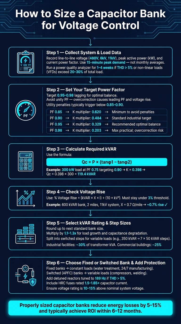
- Gather accurate load data, focusing on peak demand and power factor.
- Set a target power factor (typically 0.95–0.98 lagging).
- Calculate required kVAR using the formula: Qc = P × (tanφ1 − tanφ2).
- Check voltage rise to ensure it stays within acceptable limits (under 3%).
- Choose between fixed or switched capacitor banks based on load variability.
- Add detuned reactors if harmonics exceed 5% to prevent resonance issues.
Capacitor banks not only help avoid penalties but also extend equipment life and reduce energy losses by 5%–15%. Regular monitoring and maintenance are crucial for long-term performance.
Capacitor Bank Calculation Explained | Power Factor Correction
sbb-itb-501186b
Key Inputs for Capacitor Bank Sizing
Before diving into calculations, you need accurate data. Guessing load values or skipping a harmonic survey can lead to a capacitor bank that's either too small to make a difference or too large, introducing new issues. Here's what you should collect first.
System and Load Data Collection
Start by gathering system details like line-to-line voltage (e.g., 480V, 6 kV, or 11 kV), maximum active power (kW), and the current power factor.
"The most common mistake I see is engineers sizing capacitors based on average load instead of peak demand." - Sarah Martinez, P.E., Specap Engineering
Focus on the highest 15-minute demand, which you can find in utility bills or power meters. Avoid using monthly averages - these won't account for peak periods and could result in undercorrection, leading to utility penalties.
For a more detailed analysis, use a portable power quality analyzer over one to four weeks to capture load behavior. Facilities with SCADA systems can rely on real-time monitoring. Pay attention to Total Harmonic Distortion (THD); if it exceeds 5%, or if non-linear loads like variable frequency drives (VFDs) make up more than 20–30% of the total load, you'll need to address harmonic mitigation (discussed further below).
Once you have this data, define your voltage performance goals.
Voltage Performance Targets
The aim isn’t to reach a unity power factor. Instead, most engineers target a power factor between 0.95 and 0.98 lagging. This range avoids utility penalties (typically triggered below 0.85–0.90) while leaving enough margin to prevent overcorrection during times of lighter load.
Why avoid overcorrection? Excess capacitance can cause a leading power factor, pushing system voltage above safe limits. This could exceed the 3% voltage rise threshold and even lead to ferroresonance with transformers.
Here's a quick reference table showing how your target power factor affects sizing calculations:
| Target Power Factor | tan(arccos(PF)) Multiplier | Notes |
|---|---|---|
| 0.85 | 0.620 | Minimum to avoid most utility penalties |
| 0.90 | 0.484 | Standard industrial target |
| 0.95 | 0.329 | Recommended for optimal balance |
| 0.98 | 0.203 | Maximum practical target; overcorrection risk |
With your target set, it’s time to consider network and equipment limitations.
Network and Equipment Constraints
Using your load data and performance targets, evaluate system constraints like transformer capacity, conductor ampacity, and harmonic resonance risks.
Your transformer's kVA rating and impedance dictate how much reactive power the system can handle before voltage rises become problematic. Conductor ampacity limits how much current the capacitor bank can introduce to specific feeder segments. If your system already has high harmonic content, adding a standard capacitor bank without detuning reactors can exacerbate resonance issues. For example, in systems with 8–10% THD, standard capacitors may fail within two years unless detuned.
To prevent resonance, specify detuned reactors tuned to 189 Hz (for 60 Hz systems). This adjustment shifts the resonant frequency below the 5th harmonic. Additionally, include a 5–10% kVAR margin above your calculated requirement to account for internal system losses, and ensure the capacitor bank’s voltage rating exceeds the nominal voltage by 10–15%.
Step-by-Step Guide to Sizing Capacitor Banks
How to Size a Capacitor Bank for Voltage Control: Step-by-Step Guide
Using the system data you've collected and your performance goals, follow these steps to properly size a capacitor bank for effective voltage control.
Step 1: Calculate Reactive Power Requirements
The key formula to determine the required reactive power (Q₍c₎) is:
Q₍c₎ = P × (tan φ₁ − tan φ₂)
Here:
- P is the load in kilowatts (kW).
- φ₁ and φ₂ are the angles corresponding to the current and target power factors.
For example, imagine a facility operating at 300 kW with a power factor of 0.75, aiming to improve to 0.90. Using a multiplier (K) of 0.398 from the table below, the required reactive power is:
Q₍c₎ = 0.398 × 300 = 119.4 kVAR
| Existing PF | Target PF: 0.90 | Target PF: 0.95 | Target PF: 0.98 |
|---|---|---|---|
| 0.70 | 0.536 | 0.691 | 0.824 |
| 0.75 | 0.398 | 0.553 | 0.686 |
| 0.80 | 0.266 | 0.421 | 0.554 |
| 0.85 | 0.135 | 0.290 | 0.423 |
To calculate required kVAR, multiply your kW load by the appropriate K value.
For larger setups, consider using load flow analysis. For instance, during the 2014 Batu Hijau mining operation, engineers analyzed a 2.5 MVA transformer running at 92% load with a 0.71 power factor. They determined that a 400 kVAR automatic capacitor bank reduced transformer loading to 73%. This avoided costly cable modifications or load shedding. This example highlights how accurate sizing can prevent unnecessary system changes.
After calculating reactive power, ensure it doesn't cause an excessive voltage rise.
Step 2: Determine Voltage Rise from kVAR
Before finalizing the kVAR rating, check that the added reactive power won't push the system voltage beyond acceptable limits. Use this formula to estimate voltage rise:
% Voltage Rise = (kVAR × X × l) ÷ (10 × kV²)
Where:
- X = line reactance (ohms per mile)
- l = distance (miles)
- kV = phase-to-phase voltage (kV)
Since the formula includes kV² in the denominator, increasing the system voltage significantly reduces voltage rise. For example, a 600 kVAR capacitor bank located 2 miles from the source on an 11 kV system with a line reactance of 0.7 ohms/mile results in a voltage rise of about 0.7%. This falls well within the typical 3% threshold. Performing this check early ensures you avoid oversizing the capacitor bank.
Once the voltage rise is verified, move on to selecting the final kVAR rating and step sizes.
Step 3: Select Total kVAR Rating and Step Sizes
After confirming that your calculated Q₍c₎ meets the voltage rise requirements, round up to the next standard bank size. Multiply the kVAR rating by a factor of 1.1 to 1.3 to account for future load growth and natural capacitance degradation over time.
For systems with fluctuating loads, divide the total rating into smaller, switched steps. For example, a 350 kVAR bank could be split into seven 50 kVAR steps. This allows for finer adjustments to load changes and prevents overcorrection during lighter load periods. Typically, industrial facilities size capacitor banks at about 30% of transformer kVA, while commercial buildings generally require around 25%.
"A capacitor bank is one of the important components of a substation as it is used for improving operational efficiency, reduce system losses, stabilize voltage, and comply with regulatory standards." - Tutorialspoint
Finally, add a 5–10% kVAR buffer to account for internal losses, and ensure the bank's voltage rating exceeds the nominal system voltage by 10–15% before finalizing your choice.
Best Practices for Capacitor Bank Configuration
Once you've calculated the necessary kVAR rating, the next step is configuring the capacitor bank. A poor configuration can lead to overvoltage, equipment damage, or unnecessary expenses, so getting it right is critical.
Fixed vs. Switched Capacitor Banks
The decision between fixed and switched capacitor banks depends on one key factor: how much your load fluctuates during the day.
Fixed capacitor banks are always connected to the system. They’re straightforward, budget-friendly, and ideal for facilities with steady, continuous loads - like water treatment plants or manufacturing processes that run 24/7. However, they can cause overvoltage during times of low demand, which can be just as damaging as undervoltage.
Switched (automatic) capacitor banks, on the other hand, connect and disconnect based on real-time conditions. These are better suited for facilities with variable loads, such as those with changing production schedules or equipment like air compressors and welding machines that cycle on and off. While they offer flexibility, they come with a higher upfront cost and require more maintenance.
| Feature | Fixed Banks | Switched Banks |
|---|---|---|
| Best For | Constant loads, small substations | Variable loads, large industrial/commercial systems |
| Control | Permanently connected; manual | APFC relays, voltage sensors, or time-based controllers |
| Main Risk | Overvoltage during light-load periods | Higher initial cost; more maintenance required |
| Primary Benefit | Simple installation; lower cost | Prevents overcorrection; adapts to load changes |
These configurations lay the foundation for implementing dynamic switching strategies.
Control Strategies for Switching
Switched capacitor banks rely on Automatic Power Factor Correction (APFC) relays to monitor the system and adjust capacitor stages in real time. This ensures the power factor stays within the desired range - typically 0.90 or higher, which is the minimum requirement for many U.S. utilities for facilities with demands of 300 kW or more.
For facilities with predictable schedules, time-based controllers are a practical choice, activating banks at the start of shifts and deactivating them at night. For more complex and dynamic load profiles, PLC-based controllers can manage capacitor switching in coordination with voltage regulators and transformer load tap changers (LTCs). This prevents conflicts between devices. Advanced controllers should also include inrush current limiting measures, such as pre-insertion resistors or thyristor switching at voltage zero-crossing.
Protection and Equipment Ratings
Once the switching strategy is in place, implementing robust protection measures is crucial. Each capacitor bank requires proper safeguards, including:
- HRC (High Rupture Capacity) fuses for each parallel branch, rated at 1.5 to 1.65 times the capacitor’s current capacity. These handle harmonic overcurrents without unnecessary tripping.
- Overcurrent protection relays, set to trip the bank if the current exceeds 1.3 times its rated value.
- Discharge resistors to reduce residual voltage to below 50V within 5 minutes, as required by IEEE standards.
In systems where Total Harmonic Distortion (THD) exceeds 5% - a common issue in facilities using variable frequency drives (VFDs) - detuned reactors (series inductors) are needed. These shift the resonant frequency below the 5th harmonic, typically tuning to 189 Hz on 60 Hz systems.
"Many engineers ignore harmonics until there's a problem... The cost of replacing failed capacitors plus the downtime far exceeds the 20–30% premium for detuned capacitors." - Sarah Martinez, P.E., Licensed Electrical Engineer
The following table outlines key standards governing capacitor bank design and protection in the U.S.:
| Standard | Scope |
|---|---|
| IEEE 18 | Ratings and testing for shunt power capacitors |
| IEEE 1036 | Application guide for sizing and installation |
| IEC 60831 | Shunt capacitors for AC systems up to 1,000V |
| NEMA CP 1 | Ratings and application guidelines |
Finally, ensure there’s at least 10mm of spacing between capacitor units to allow for proper cooling. Keep in mind that capacitor life is cut in half for every 10°F increase above the rated temperature.
Verification and Long-Term Performance
Commissioning and Field Verification
Commissioning ensures the capacitor bank operates as designed. To confirm performance, use a power factor meter for real-time cosφ readings, or compare active (kWh) and reactive (kVArh) energy meter data over a full 24-hour cycle or production shift to calculate an accurate average.
During this process, check that the power factor achieves 0.95–0.98 lagging and that voltage rise stays under 3%, aligning with the pre-determined limits. Verify that APFC relays are correctly managing capacitor stages in response to load variations. Additionally, recalculate the resonant frequency using the formula (h₍resonant₎ = √(S₍cc₎/Q₍c₎)) to ensure it avoids the 5th and 7th harmonics, which are commonly produced by VFDs and rectifiers.
Once commissioning confirms the system's performance, ongoing monitoring is necessary to maintain stability.
Monitoring and Maintenance
Regular monitoring and maintenance are critical to keeping the system running efficiently. A structured schedule can help prevent performance issues:
- Monthly: Review utility bills for power factor penalties.
- Quarterly: Cross-check power factor readings with APFC relay data.
- Annually: Conduct a full power quality audit and inspect components such as fuses, contactors, reactors, and capacitor units for signs of wear or heat damage.
For substation installations, real-time monitoring through SCADA systems provides oversight and enables remote adjustments.
"For any facility with >20% load variation, I always recommend automatic capacitor banks, even if the initial cost is higher. The long-term benefits far outweigh the cost difference." - Sarah Martinez, P.E., Power Systems Designer
Most industrial setups achieve a return on investment within 6 to 12 months, with energy losses in cables and transformers decreasing by 5–15% after correction.
Adjusting Performance as Loads Change
As operational demands shift, periodic reviews and updates help maintain optimal performance. If power factor penalties persist or voltage deviations exceed the ±5% tolerance band, recheck capacitor sizing and control settings. When recalculating kVAR requirements, consider adding a 10–30% safety margin to accommodate changes.
For environments with load variations over 20% or where VFDs and other non-linear loads make up 20–30% or more of the total load, revisit control settings and detuned reactor configurations. Without these adjustments, capacitor banks in VFD-heavy setups may fail within 6 to 18 months.
Conclusion: Key Takeaways for Capacitor Bank Sizing
Accurate sizing and proper configuration are essential for effective voltage control. Start by determining the required reactive power using the formula Qc = P × (tanφ1 − tanφ2). Don’t forget to account for system losses and potential future load growth when making your calculations. Additionally, choose equipment with a rated voltage that is 10–15% higher than the nominal system voltage to maintain reliability over time.
Make sure the resonant frequency you calculate avoids common harmonic frequencies, such as the 5th and 7th. If necessary, consider detuned filters set to 4.8 p.u. to mitigate harmonic interference.
Selecting the right capacitor bank type depends on your load profile. Fixed banks are ideal for stable, consistent loads, while switched banks with APFC relays are better suited for fluctuating loads. These relays adjust compensation in real time, improving performance and helping avoid penalties.
Remember, system parameters can change over time due to load shifts or equipment aging. Regular monitoring and adjustments are essential to ensure continued efficiency.
When you're ready to implement your design, focus on sourcing high-quality components. Electrical Trader offers a wide selection of new and used capacitor banks, reactors, and protective devices to help keep your network running efficiently for years to come.
FAQs
Do I size a capacitor bank from peak kW or average kW?
When deciding on the right approach, consider your goals and how your utility billing works. If your main aim is to correct the power factor to address demand charges, focus on peak demand. This ensures the system operates effectively during periods of high load, though it usually means opting for a larger capacitor bank.
On the other hand, if you're prioritizing overall efficiency, base the calculations on average values derived from monthly data. Reviewing your power bills can help you size the bank to handle the worst-case month effectively.
When do I need detuned reactors for harmonics?
Detuned reactors play a crucial role in managing power quality when Total Harmonic Distortion (THD) exceeds 5%. This typically happens due to devices like variable frequency drives (VFDs) or rectifiers. When a system analysis reveals resonance near critical harmonic frequencies - such as the 5th, 7th, 11th, or 13th - detuned filter banks are an effective solution. They help reduce harmonic distortion and safeguard equipment from potential damage. Electrical Trader offers tools and equipment designed to tackle these power quality issues efficiently.
How do I pick step sizes for an automatic capacitor bank?
When designing step sizes for automatic capacitor banks, it’s all about matching the system’s needs. These step sizes depend on how the parallel capacitor units are arranged and controlled by the power factor controller.
Here’s a tip: select step sizes so that the total reactive power capacity is 5%-10% higher than your calculated needs. This extra margin helps account for system losses.
For systems with fluctuating loads, opt for smaller and more frequent steps using static switches. This allows the system to adapt quickly to changes. On the other hand, if the load is steady, standard contactor-controlled steps are sufficient.
Lastly, double-check that the unit ratings are compatible with the system voltage to ensure smooth operation.