
How Load Balancing Impacts Power Factor Correction
Load balancing and power factor correction (PFC) are two essential practices for improving electrical system efficiency. Load balancing ensures equal distribution of electrical loads across phases, reducing stress on equipment and minimizing neutral currents. PFC improves energy efficiency by reducing reactive power, which doesn’t contribute to useful work. Combining these practices helps facilities avoid energy losses, equipment damage, and utility penalties.
Key Points:
- Load Balancing: Distributes electrical loads evenly across phases, stabilizing currents and voltages.
- Power Factor Correction (PFC): Reduces reactive power to improve energy efficiency, often necessary for industrial systems with power factors below 0.85–0.95.
- Connection: Unbalanced loads disrupt PFC, leading to inefficiencies, increased costs, and equipment wear.
- Implementation: Start with load balancing before applying PFC. Use tools like automatic capacitor banks and real-time monitoring systems for best results.
Balancing loads first ensures PFC systems work effectively, reducing energy waste and preventing equipment failures. Facilities can lower costs, extend equipment lifespan, and maintain reliable power systems.
Power Factor Correction and Its Benefits Explained From First Principles | FE Electrical & PE Power
sbb-itb-501186b
How Load Imbalances Affect Power Systems
Understanding load imbalances is key to maintaining efficient and reliable power systems. These imbalances can have far-reaching effects, from equipment damage to increased operational costs.
Voltage Imbalance and Equipment Effects
Uneven load distribution leads to differences in phase voltages, which can stress electrical equipment by increasing neutral currents, causing resistive heating, and even posing fire risks. Ideally, a balanced system ensures the neutral carries no current. However, even a small imbalance - like a 10% phase unbalance in a 100A system - can result in a 17A neutral current, creating excessive heat and potential hazards.
Motors are particularly vulnerable to voltage imbalances. When voltages are uneven, they generate a "negative sequence component" that creates a torque opposing the motor's rotation. Electrical engineer Edvard Csanyi explains:
The application of negative sequence voltage to the terminal of a 3-phase machine produces a flux, which rotates in the opposite direction to that produced by positive sequence voltage.
This counteracting torque forces the motor to expend more energy while delivering less output. Additionally, the negative sequence induces currents in the rotor at twice the system's frequency - 120 Hz in a 60 Hz system - causing rapid overheating. These voltage imbalances also disrupt reactive power distribution, complicating standard power factor correction efforts.
Reactive Power Distribution Problems
Load imbalances lead to uneven reactive power distribution, which undermines power factor correction. Single-phase loads with varying power factors across phases can cause centralized capacitor banks to over-correct one phase while under-correcting another.
The issue becomes more severe with three-phase equipment like motors and transformers. Voltage imbalances introduce negative sequence currents that oppose normal current flow and contribute no useful work. As electrical engineer JRaef notes:
When line voltages are unbalanced, 3 phase consumers and inductive devices such as motors, generators and transformers will be forced to deal with added internal heating effects of 'negative sequence current' that flows in them as a result.
This additional internal heating not only wastes energy but also stresses insulation, further compounding energy losses and increasing the likelihood of equipment failure.
Energy Losses and Cost Increases
A current imbalance of just 10% can increase copper losses by about 1%. When combined with 30% Total Harmonic Distortion (THD), neutral currents can approach the magnitude of phase currents, significantly amplifying energy losses.
Utilities in the United States often impose penalties when power factors drop below 0.85–0.95 lagging. The excess heat generated by imbalances shortens the lifespan of transformers, motors, and cables, driving up replacement costs and causing downtime. To mitigate these issues, facilities should limit unbalanced single-phase load distribution to no more than 10% for three-phase 4-wire circuits exceeding 100A.
Why Load Balancing Improves Power Factor Correction
Balanced vs Unbalanced Electrical Loads: Impact on Power Factor Correction
To get the best results from power factor correction, load balancing needs to happen first - or at least at the same time. Without it, unbalanced loads can interfere with the effectiveness of traditional capacitor-based correction systems, sometimes making things worse instead of better.
Limitations of Capacitor-Based Power Factor Correction
Capacitor banks are often used to provide reactive power compensation, but they apply the same correction across all three phases. This uniform approach doesn’t work well when loads are unbalanced. Electrical engineer Mircea Chindris explains:
If the load is unbalanced, the reactive power absorption on each phases are also unsymmetrical. In this case the three phase reactive compensation can have negative consequences; some phases may be over-compensating other less-compensating
When compensation isn’t tailored to each phase, one phase might end up over-corrected while another is under-corrected. This mismatch can destabilize voltage and, in extreme cases, push lightly loaded phases into a leading power factor state. That can cause voltage surges and even resonance issues.
The problem gets worse in environments with high harmonic content, such as facilities using variable frequency drives. Capacitors in these settings can amplify harmonic currents, which may lead to equipment failures in as little as 6 to 18 months. Clearly, smarter solutions are needed to address these challenges.
How Load Balancing Enhances Power Factor Correction
Balancing the load before applying power factor correction ensures that reactive power is distributed evenly across all phases. This eliminates neutral current, cutting down on energy waste. Advanced systems like DSTATCOM can handle load balancing and power factor correction at the same time, maintaining a unity power factor even during system disturbances.
Researchers B. Singh, A. Saxena, and D.P. Kothari noted:
After compensation all three supply currents are in phase with their respective phase voltages with equal magnitude resulting in a balanced load on supply system
By balancing the load, an unstable, oscillating power source is transformed into a steady, reliable one. Tests using hybrid compensation methods have shown impressive results, achieving power factors above 0.998 across load ranges of 80–110%, while also reducing total harmonic distortion to below 20%.
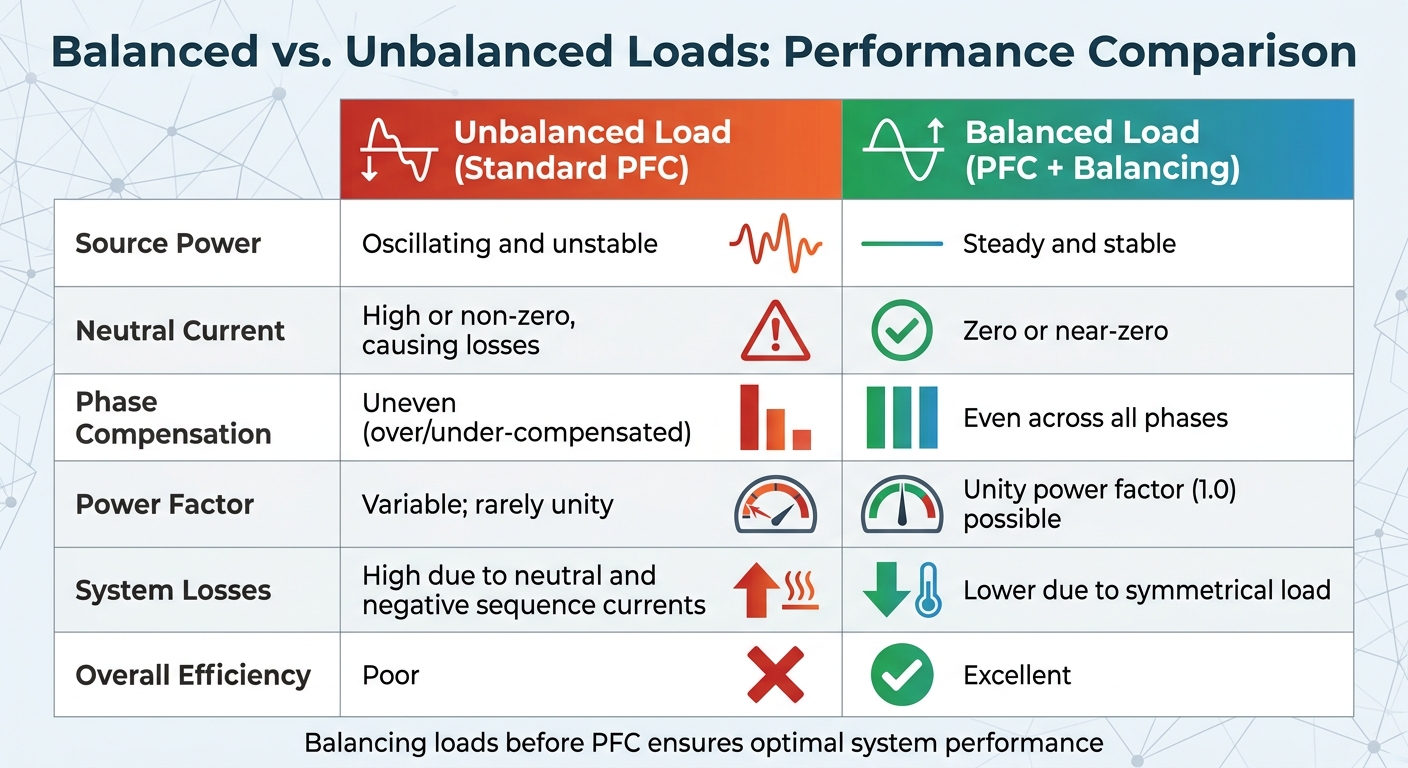
Balanced vs. Unbalanced Loads: A Comparison
Here’s a quick look at how balanced loads outperform unbalanced ones:
| Feature | Unbalanced Load (Standard PFC) | Balanced Load (PFC + Balancing) |
|---|---|---|
| Source Power | Oscillating and unstable | Steady and stable |
| Neutral Current | High or non-zero, causing losses | Zero or near-zero |
| Phase Compensation | Uneven (over/under-compensated) | Even across all phases |
| Power Factor | Variable; rarely unity | Unity power factor (1.0) possible |
| System Losses | High due to neutral and negative sequence currents | Lower due to symmetrical load |
For industrial facilities using high-power single-phase equipment like welding transformers or induction furnaces, individual phase sensing can help avoid over-compensating lightly loaded phases. Active compensation systems, such as voltage source inverters or DSTATCOMs, also offer dynamic regulation that fixed capacitor banks simply can’t provide.
Methods for Implementing Load Balancing and Power Factor Correction
Addressing the importance of balanced loads, the methods below combine load balancing with effective power factor correction. The key lies in using specialized tools and clear strategies.
Monitoring and Control Systems
Start by using power quality analyzers to measure baseline power factor and Total Harmonic Distortion (THD) at key service points. Advanced control systems can monitor and adjust correction mechanisms in real time, helping to address the challenges posed by unbalanced loads.
Automatic capacitor banks are a practical solution, as they adjust in real time by switching between 6 to 12 discrete stages. These banks add or remove capacitive kVAR as needed, adapting to load changes and avoiding over-correction. For facilities with high harmonic content - such as data centers or plants with variable frequency drives (VFDs) - Automatic Power Factor Correction (APFC) systems use power electronics to inject reactive current that counteracts harmonics.
Selecting the Right Equipment
Once monitoring is in place, choose equipment that matches your load profile. For stable and predictable loads, fixed capacitor banks are a cost-effective choice, particularly for single large motors or transformers. However, for facilities with varying loads throughout the day, automatic switched capacitor banks are necessary to prevent over-correction during periods of light load. These systems can cost up to twice as much as fixed banks.
If your facility's load includes 20–30% or more non-linear sources (like VFDs), detuned capacitor banks with series reactors are essential. Standard detuning levels are 7% for filtering 5th harmonics and 14% for environments with significant 3rd harmonics. These detuned banks are designed to handle harmonic-rich environments, reducing the risk of equipment failure.
For example, at the Batu Hijau mining operation in 2014, installing a 400 kVAR automatic capacitor bank reduced transformer loading from 92% to 73%, freeing up 168 kVA of system capacity.
When selecting transformers and breakers, ensure they are rated for 1.5 times the capacitor's current to handle inrush and potential harmonic overcurrent. Additionally, avoid connecting power factor correction capacitors directly to the output terminals of a VFD, as this can damage the drive's power semiconductors.
Best Practices for Implementation
Aim for a power factor between 0.95 and 0.98 lagging. Overcorrecting to unity or a leading power factor can lead to voltage rises, relay misoperation, and ferroresonance.
"A leading power factor (caused by too much capacitance) can raise system voltage above acceptable limits, cause ferroresonance with transformers, and interact destructively with the network."
Ensure systems are equipped with discharge resistors that reduce voltage to below 50V within 60 seconds of disconnection, as required by IEC 60831-1 standards. Proper ventilation is also crucial, as capacitors and detuned reactors generate significant heat during operation. Without adequate cooling, dielectric materials can break down prematurely.
Perform quarterly inspections to check for signs of wear, such as bulging or discoloration on capacitor banks. Regular load surveys can help track changes in your facility's power profile, allowing you to adjust correction equipment as needed. These steps play a key role in improving the reliability of power systems.
Conclusion: Improving Power Systems Through Load Balancing and Power Factor Correction
Fixing load imbalances before implementing power factor correction is the cornerstone of a well-functioning electrical system. When phase loads are balanced, the supply currents align with their respective voltages and maintain equal magnitude across all three phases. This synchronization ensures that phase currents work in harmony, enabling capacitor banks to operate efficiently and preventing unnecessary currents that could compromise the performance of correction equipment.
Balanced loads don't just enhance technical performance - they also bring notable financial benefits. Properly balanced systems can help avoid utility penalties, which often apply when the power factor drops below thresholds like 0.85 to 0.95. Additionally, balancing reduces resistive losses in conductors and transformers, recaptures wasted capacity in existing infrastructure, and avoids costly equipment upgrades. While the energy savings from power factor correction might be modest (less than 1%), it significantly reduces demand charges, leading to lower energy bills. With these savings, the investment in correction measures typically pays off quickly.
"A low power factor means you're not fully utilizing the electrical power for which you are paying." - Tommy Northcott, Professional Engineer
The process starts with choosing the right strategy for your facility’s specific needs. Conduct a load survey using power quality analyzers to establish baseline conditions and pinpoint imbalances. Address issues like undersized motors before introducing capacitors to handle low lagging power factors. For facilities with variable loads, automatic switched capacitor banks are a smart option. While they cost 1.5 to 2 times more than fixed systems, they prevent over-correction during periods of low load.
Aim for a power factor between 0.95 and 0.98 lagging. Correcting beyond 0.98 can lead to voltage increases and relay misoperations. By combining load balancing with power factor correction, and incorporating regular inspections and load monitoring, facilities can deliver cleaner power, extend the lifespan of equipment, and maximize the value of their electrical infrastructure. This integrated approach ensures a more reliable and cost-effective power system.
FAQs
How do I know if my facility has a phase load imbalance?
To check for imbalances in your three-phase system, start by measuring the current or power drawn by each phase. If the levels are not equal, it usually points to an imbalance. This often happens when equipment is distributed unevenly across phases or when large single-phase loads are present.
Using tools like smart meters can make it easier to spot these discrepancies. Additionally, keeping an eye on voltage levels can help. Uneven load distribution may lead to more significant voltage drops on specific phases, which is another sign of imbalance.
Why can capacitor banks make power factor worse on unbalanced loads?
Capacitor banks, while useful in improving power factor, can actually make it worse when dealing with unbalanced loads. This happens because they can trigger harmonic resonance, which amplifies harmonic currents in the system. If the capacitor bank isn't properly aligned with the system's harmonic profile, it might also cause voltage instability and lower overall system efficiency. To prevent these problems, careful and precise specification is absolutely necessary.
When do I need detuned capacitor banks instead of standard PFC?
Detuned capacitor banks are essential in systems where harmonic distortion arises from nonlinear loads like VFDs or rectifiers. Harmonics can lead to resonance issues, potentially damaging capacitors or diminishing the efficiency of power factor correction. By detuning, these banks help minimize the effects of harmonics, ensuring the system operates more reliably.


