
How to Inspect Industrial Equipment for NEC Compliance
Inspecting industrial equipment for NEC compliance ensures safety, reduces risks, and avoids costly penalties. The National Electrical Code (NEC), updated every three years, sets the standards for safe electrical installations. Non-compliance can lead to OSHA fines up to $161,323, equipment failures, and hazards like arc flashes or fires. Here's a quick guide to the process:
- Review Documentation: Check system records like panel directories, load calculations, and single-line diagrams for accuracy and NEC alignment.
- Visual Inspection: Look for damaged enclosures, missing labels, improper clearances, and grounding issues.
- Electrical Testing: Perform grounding resistance, overcurrent protection, and insulation integrity tests to verify safety and functionality.
- Address Violations: Correct common issues like working space obstructions, improper grounding, and outdated labels.
- Compile Reports: Document findings and test results to meet Authority Having Jurisdiction (AHJ) requirements.
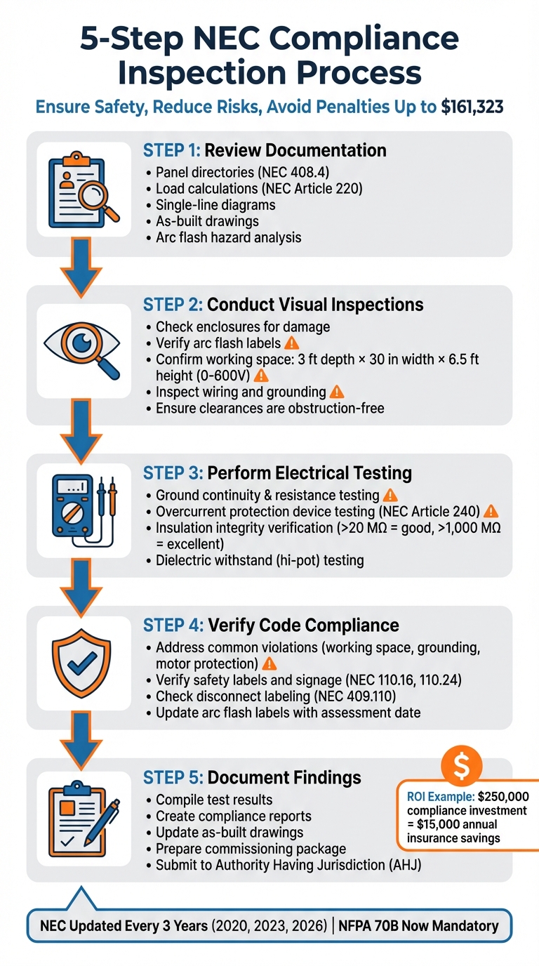
5-Step NEC Compliance Inspection Process for Industrial Equipment
Inspecting An Electrical Panel
sbb-itb-501186b
Step 1: Review Documentation and Electrical System Records
Start by digging into the documentation. Reviewing records upfront helps you understand the system’s intended configuration and flags any discrepancies before you even step into the field. This step is crucial for identifying potential compliance issues on paper, setting the stage for a smoother inspection and testing process.
Michael Rodriguez, P.E., a Senior Power Systems Engineer, sums it up perfectly:
"Good documentation is your best defense against code violations. When inspectors question something, I can show documentation proving compliance. Poor documentation leads to failed inspections and expensive corrections".
The aim here is to compare the existing records to current NEC standards, looking for "documentation drift" - those pesky mismatches between what’s recorded and what’s actually installed due to undocumented changes.
NEC Documentation Requirements
The NEC doesn’t bundle all its documentation rules into one section; instead, they’re spread across various articles. Here are some key areas to focus on:
- Panel directories: Article 408.4 requires these to be legible and accurately list each circuit’s purpose.
- Load calculations: Article 220 ensures feeders and branch circuits are appropriately sized for the load.
- Emergency and standby systems: Articles 700 and 701 mandate written records of required tests and inspections.
- As-built drawings: These should reflect the actual installation, including field changes like altered conduit paths or updated breaker sizes.
- Single-line diagrams (SLD): These illustrate the electrical distribution from the utility service to the final branch circuits.
- Equipment submittals and cut sheets: Manufacturer documentation verifies components meet safety standards.
- Hazardous location classifications: For sites with flammable gases (Class I) or combustible dust (Class II), documentation must prove compliance with Articles 500–516.
Look for redline markups that show field modifications, as these need to be integrated into the final as-built documents. Also, ensure arc flash hazard analysis records are up to date to establish safe working conditions and PPE requirements. Keep in mind, some jurisdictions may require as-built drawings for a Certificate of Occupancy, and OSHA regulations (29 CFR 1910.303) demand that electrical equipment be maintained according to applicable standards. Inaccurate or missing documentation can lead to safety violations.
| Document Type | Relevant NEC Article(s) | Purpose for Inspection |
|---|---|---|
| Panel Directories | 408.4 | Verify every circuit is legibly and accurately identified. |
| Load Calculations | 220 | Confirm conductors and protection are sized for the load. |
| Service Identification | 230 | Ensure service entrance components are properly labeled. |
| Motor Schedules | 430 | Verify FLC, overload settings, and disconnect locations. |
| Emergency System Records | 700, 701 | Confirm written records of mandatory tests and inspections. |
| Working Space Plans | 110.26 | Pre-verify clearance and accessibility for live parts. |
| Hazardous Classifications | 500–516 | Ensure equipment is rated for specific gases or dusts. |
Cross-Reference System Records With NEC Standards
Once you’ve reviewed the individual documents, compare them against NEC standards to catch any inconsistencies. Start with single-line diagrams and verify compliance with Article 215 (Feeders) and Article 240 (Overcurrent Protection). This ensures conductor sizes and overcurrent protection devices (OCPDs) are properly matched to the load. For motor circuits, reference NEC Table 430.250 for three-phase motor full-load current (FLC) values - avoid relying on nameplate ratings - to confirm correct sizing for overcurrent and overload protection.
Check equipment layout drawings against Article 110.26 to confirm adequate working space. For equipment rated 0–600V, you need at least 3 feet of depth, 30 inches of width, and 6.5 feet of height. Fixing these issues during the design phase is far cheaper than relocating panels after installation. Compare panel directories to actual field wiring; mismatches here are a compliance issue under Article 408.4.
Finally, review past inspection reports and test records. These provide valuable benchmarks for future diagnostics, like power quality and insulation resistance. They can also reveal recurring problems, such as arcing faults or neutral conductor failures, and confirm whether previous safety issues - like exposed energized conductors - were resolved permanently. Pay close attention to any "red-tag" orders to ensure critical hazards have been addressed.
Step 2: Conduct Visual Inspections of Equipment
After reviewing the documentation, the next step is to physically inspect the equipment. This process helps uncover issues that might not be evident in paperwork. Look for physical compliance problems like damaged enclosures, insufficient clearances, missing labels, or improper storage. These visual checks lay the groundwork for the electrical testing that follows.
Inspect Electrical Enclosures and Components
Start by examining enclosures for visible signs of damage, such as dents, rust, or missing covers that could expose energized components. Check that enclosures are securely mounted and that any open knockouts are properly sealed.
Confirm that all service and feeder equipment display current arc flash hazard labels. These labels should include details like system voltage, arc flash boundary, incident energy (or minimum PPE level), and the date of the last assessment. If labels are faded, peeling, or obscured, they need to be replaced immediately. Additionally, ensure that available fault current markings are present on service equipment in non-dwelling units, as required by NEC 110.24. These markings must include the maximum fault current value and the calculation date.
Once you’ve checked enclosures and labels, move on to evaluate wiring integrity, grounding, and clearance requirements.
Check Wiring, Grounding, and Clearances
According to NEC Section 110.26(A), electrical equipment rated between 0–600V must have a working space with minimum dimensions of 3 feet in depth, 30 inches in width, and 6.5 feet in height. This space must allow safe access and egress for operation and maintenance. Measure these areas to verify compliance with NEC standards.
The working space must remain clear at all times - storage of items like janitorial supplies, spare parts, or boxes is not permitted. Electrical consultant Mark Lamendola emphasizes this point:
"Those spaces must be kept clear [Sec. 110.26(B)]. They cannot be used for storage".
Ensure the floor or platform in the working area is level and flat, as uneven surfaces could pose tripping hazards during maintenance. Check that electrical room doors open fully and that access paths are free of obstructions.
Next, inspect the wiring to confirm compliance with NEC standards. Verify proper conductor sizing (NEC Article 310), box fill limits (NEC Article 314), and correct support spacing for cables. During this step, also confirm that the grounding electrode systems (NEC Article 250) are properly bonded and that all required GFCI and AFCI protections are installed.
While these visual inspections can identify a wide range of physical code violations, they won’t reveal all energized fault conditions. To address those, thermal imaging and diagnostic testing will be performed in Step 3.
Step 3: Perform Electrical Testing for Safety and Compliance
Once the physical inspections from Step 2 are complete, it’s time to dive into electrical testing. These tests are critical for identifying issues that visual checks might miss and ensuring everything aligns with NEC standards. They validate the performance of grounding systems, overcurrent devices, and insulation. The InterNational Electrical Testing Association's Acceptance Testing Specifications (ANSI/NETA ATS) outlines the procedures and rejection criteria for these tests.
Before starting, make sure the circuits are de-energized, follow lockout/tagout protocols, disconnect sensitive electronics, and equip yourself with proper PPE, including arc-rated clothing and insulated gloves. These precautions build on the visual inspections and confirm the system’s electrical integrity.
Ground Continuity and Resistance Testing
Grounding systems play a vital role in safety by providing a low-impedance path for fault currents. This ensures that overcurrent protection devices trip quickly, reducing the risk of shocks or fires. Ground continuity testing checks that all equipment is securely connected to the grounding conductor, preventing dangerous "floating" voltages.
To measure the resistance of the grounding electrode system, use techniques like the fall-of-potential method or stakeless clamp-on tests. IEEE 81 offers specific guidance on acceptable resistance values. Common issues to watch for include missing ground wires, poor bonding, or inadequate grounding.
Overcurrent Protection Device Testing
Overcurrent protection devices (OCPDs), such as circuit breakers and fuses, must comply with NEC Article 240. These devices come in standard sizes ranging from 15 A to 6,000 A. Testing ensures that trip times, relay settings, and interrupting ratings match the system’s coordination study, so the device closest to a fault activates first.
For motor circuits, NEC Article 430 provides specific guidelines. For example, branch-circuit protection is typically set at 250% of Full Load Current (FLC) for inverse time breakers, with instantaneous trip settings between 800% and 1,300% of FLC. Overload protection for motors with a service factor of 1.15 or higher is usually set at 125% of FLC but should not exceed 140%.
Functional testing involves energizing the system at its rated voltage to verify phase balance, voltage regulation, and thermal performance under load conditions. This step can catch coordination problems before they lead to unexpected downtime or safety risks.
Once overcurrent functions are verified, move on to insulation checks.
Insulation Integrity Verification
To assess insulation quality, use a megohmmeter with a test voltage between 500 and 2,500 VDC. Readings above 20 MΩ indicate good insulation, while values over 1,000 MΩ suggest excellent quality. Apply the voltage for 60 seconds to stabilize the reading. Any rapid fluctuations during the test could point to insulation breakdown or a circuit fault.
For a deeper analysis, conduct dielectric withstand (hi-pot) testing. This involves applying a higher-than-normal AC or DC voltage to detect insulation defects that might not show up in standard megger tests. IEEE 400 provides the framework for hi-pot testing power cables. Julia Klein, Product Manager at BARTEC, highlights the risks of skipping these tests:
"A low insulation resistance indicates voltage leakage, damage to the trace heater, and possible insulation faults. Failure to regularly conduct a Megger test could result in tripping of circuit breakers, electrical shock, or even a fire".
After completing all the tests, compile the results for review by the Authority Having Jurisdiction (AHJ). This step is essential for securing the necessary permits to operate.
Step 4: Verify Code Compliance and Safety Standards
Before energizing equipment, it's crucial to verify that all test results meet NEC (National Electrical Code) standards. This step ensures compliance and addresses any safety concerns that testing alone might not reveal. Use the documentation and results from previous steps to confirm adherence to the NEC requirements. Remember, the NEC is updated every three years (2020, 2023, 2026), so always refer to the edition specific to your jurisdiction.
Pay particular attention to the NEC articles related to the type of equipment and installation environment. Key areas to review include working space clearances, labeling, and proper identification of power sources.
Common NEC Violations
Some NEC violations occur more frequently than others. Here are a few to watch out for:
-
Working Space Violations: NEC 110.26 specifies clearances for equipment rated 0–600V. Michael Rodriguez, P.E., a Senior Power Systems Engineer, highlights this as a common issue:
"The most common violation is working space. Panels mounted 18 inches from walls violate the 3-foot working space requirement. It's a simple violation to fix during design but expensive to fix after installation".
- Grounding and Bonding Issues: NEC 250 violations often involve improper neutral-to-ground bonding at subpanels or loose terminations that may not have been caught during earlier testing.
- Motor Protection Errors: NEC 430.32 violations frequently stem from incorrect overload settings. These should generally be set between 115% and 125% of the Full-Load Current (FLC), depending on the service factor.
- Double-Tapped Breakers: NEC 408.36 prohibits connecting two wires under a lug rated for one. Fixing this requires adding a new breaker or using a tandem breaker rated for two wires.
- Labeling Problems: NEC 408.4 requires accurate circuit directories. Missing or outdated labels create operational risks and should be updated immediately.
In one case, correcting safety and hazardous location violations in a 100,000 sq. ft. industrial facility cost $250,000 but resulted in $15,000 annual savings on insurance premiums.
| Violation Type | NEC Article | Corrective Action |
|---|---|---|
| Working Space Obstruction | 110.26 | Relocate equipment or clear 30"W × 36"D × 6.5'H area |
| Missing GFCI Protection | 210.8 | Install GFCI-rated breakers or receptacles in required areas |
| Improper Motor Overload | 430.32 | Adjust settings to 115–125% of FLC; install missing relays |
| Unlabeled Circuits | 408.4 | Create and install legible, accurate circuit directories |
| Double-Tapped Breakers | 408.36 | Add a new breaker or use a tandem breaker rated for two wires |
| Missing Grounding | 250 | Install proper grounding conductors and confirm bonding |
Verify Safety Labels, Signage, and Disconnects
Once common violations are addressed, shift your focus to proper labeling and signage, which are critical for compliance.
The 2026 NEC introduced updates to arc flash labeling under Section 110.16. The previous 1,000A threshold has been removed, meaning all service and feeder-supplied equipment in non-dwelling units now requires arc flash hazard markings, regardless of size. Even small safety switches for HVAC systems or motors need proper labels.
Dean Austin, Senior Electrical Specialist at NFPA, explains the updated requirements:
"The 2026 NEC has made the marking requirements more explicit, requiring that one of the main items being displayed must now be the date the assessment was completed, rather than the date the label was applied".
Arc flash labels must include system voltage, arc flash boundary, incident energy/PPE level, and the assessment date. Ensure labels are durable and resistant to environmental factors like UV exposure, moisture, or workplace chemicals, as required by NEC 110.11.
For industrial control panels, NEC 409.110 mandates labels that display the nominal system voltage and identify each power source entering the panel. If circuits remain energized when the main disconnect is off, apply a warning label specifying the voltage and external source (e.g., "Source: MCC Panel 3"). Generic "danger" signs are not sufficient.
Service equipment must also comply with NEC 110.24, requiring field-marked labels that show the maximum available fault current and the date of calculation. Any modifications affecting the fault current require recalculation and updated labels.
| Label Type | NEC Reference | Required Information |
|---|---|---|
| Available Fault Current | 110.24 | Calculated fault current value and date of calculation |
| Arc Flash Hazard | 110.16 | Voltage, boundary, incident energy/PPE level, and assessment date |
| Control Panel Nameplate | 409.110 | Nominal system voltage and identification of each power source |
| Multiple Sources | 409.110 / NFPA 70E | Warning of multiple sources, voltage level, and source identification |
Step 5: Document Findings and Generate Compliance Reports
After completing equipment testing and verifying compliance in Steps 3 and 4, the next step is to document all findings and create a detailed compliance report.
Proper documentation is key to establishing a legally defensible compliance record. The Authority Having Jurisdiction (AHJ), as defined in NFPA 70 Article 100, has the final say on code compliance and requires complete, well-organized records before granting approval for energization. Missing or incomplete documentation can delay your project and result in re-inspection fees ranging from $50 to $200 per visit.
Your compliance report should include several key elements:
- Single-line diagrams: Ensure these reflect the updated installation and any authorized changes.
- Equipment specifications: Match specifications to the installed components.
- Approved permits: Include all necessary permits.
- Electrical test results: Record insulation resistance readings in megohms (aim for values above 1 MΩ for 600V systems), ground resistance measurements (typically 5 Ω or 25 Ω depending on system criticality), and protective device performance data such as trip times and operating currents. Note the temperature and humidity during insulation tests, as these factors can influence megohm readings.
Chuck Fox, the Owner of PowerSafe Consulting, highlights the importance of thorough documentation:
"Creating tasking documentation records of all maintenance activities, including work performed, findings, and any corrective actions, is a critical element of the overall electrical maintenance program".
Field Labeling and Report Structure
Before requesting final approval, confirm that all field labeling complies with current NEC requirements. For example, circuit directories under NEC 408.4 must accurately identify every circuit in the panelboard. Missing or incorrect labeling is a common issue that often leads to re-inspections. Additionally, Articles 700 and 701 require written records of all tests and inspections for emergency and standby systems.
Organize your findings into three categories for clarity:
- Pass: Fully meets code requirements.
- Deficiency: Requires correction, with specific NEC references included.
- Immediate Hazard: Critical safety issues, such as exposed energized conductors, that demand immediate shutdown.
These classifications help inspectors quickly assess compliance and prioritize safety concerns. Update original plans with actual field conditions to create finalized as-built drawings, which form a critical part of the final commissioning package. For systems over 1,000V, detailed interconnection drawings are required under the 2023 NFPA 70 guidelines.
The table below outlines essential documentation requirements for the final reporting phase:
| Documentation Type | NEC Reference | Required Information |
|---|---|---|
| Circuit Directories | 408.4 | Accurate identification of each circuit in panelboards |
| Service Identification | Article 230 | Labeling and identification for service entrances |
| Emergency System Records | Article 700 | Written records of all tests and inspections |
| Standby System Records | Article 701 | Documentation for legally required standby systems |
Prepare for Final Approval and Energization
Once you’ve verified that all field labeling is complete, assemble and finalize the documentation required for final approval.
The final inspection will review all records from earlier phases, including plan reviews with load calculations, one-line diagrams, rough-in reports, and service/meter inspections. Ensure that any deficiencies identified in earlier phases have been resolved, as unresolved issues will prevent the AHJ from approving energization.
Check that the field-marked available fault current on service equipment labels does not exceed the equipment’s Short Circuit Current Rating (SCCR), as required by NEC 110.24. For new services, coordinate with the utility company to complete any required utility-specific inspections before energization.
Your commissioning package should include:
- As-built drawings
- Insulation resistance test results
- Ground bond verification
- Protective device functional testing reports
- Power quality baselines, including Total Harmonic Distortion (THD) and power factor measurements
Using NETA (InterNational Electrical Testing Association) specifications for acceptance testing ensures your data meets professional standards recognized by inspectors. This comprehensive documentation not only satisfies AHJ requirements but also provides a reliable baseline for future maintenance efforts.
Conclusion
Inspecting industrial equipment for NEC compliance helps reduce hazards, prevent equipment failures, and avoid costly unplanned shutdowns. By following the five-step method outlined here - what Chuck Fox, Owner of PowerSafe Consulting, calls the "Electrical Cycle of Safety" - you can effectively lower the risk of equipment issues while staying aligned with regulatory requirements.
Each step plays a vital role. Detailed documentation, visual inspections, and electrical testing not only ensure compliance with NEC standards - such as maintaining the 3-foot working space for 0–600V equipment - but also establish a strong compliance record. This can help minimize liabilities and even reduce insurance expenses. These practices not only enhance safety but also provide measurable financial benefits.
For example, a 2026 audit of a 100,000 sq. ft. facility showed that a $250,000 investment in compliance efforts resulted in annual savings of $15,000. As Rodriguez puts it:
"The cost of compliance is much less than the cost of accidents, fines, or failed inspections".
With NFPA 70B now mandatory and NEC updates occurring every three years - the most recent in 2023 and more changes expected in 2026 - regular maintenance and compliance reviews are now more important than ever .
FAQs
Which NEC edition applies in my area?
The version of the NEC (National Electrical Code) enforced in your area depends on what your local jurisdiction has adopted. Since adoption differs by state and locality, it's a good idea to reach out to your local authorities or governing body to verify which edition is currently in use.
What tools do I need for NEC compliance testing?
To stay compliant with NEC standards during electrical inspections, you'll need the right tools. Essential devices include multimeters, clamp meters, insulation resistance testers, and power quality analyzers to measure and monitor various electrical parameters. For more in-depth inspections, equipment like thermal imagers, cable fault locators, and phase rotation meters can be incredibly useful.
Safety is just as important as accuracy. Make sure to wear insulated gloves and arc-rated clothing to protect yourself while performing tests. Proper gear is non-negotiable when working with electrical systems.
What records does the AHJ usually require?
During electrical system inspections, the Authority Having Jurisdiction (AHJ) usually asks for records like inspection checklists, testing reports, and documentation that confirms compliance with the National Electrical Code (NEC) and relevant local amendments. These records are essential for verifying that all safety and regulatory standards are being followed.


