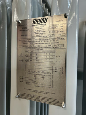
Control Vs Isolation Transformer: Key Differences
If you need steady power for contactors and relays, use a control transformer. If you need circuit separation and lower noise, use an isolation transformer. That’s the short answer.
I’d narrow the choice down to 3 things:
- Load type: coils vs. sensitive electronics
- Voltage behavior: hold-up during inrush vs. simple separation
- Panel use: control section vs. near the load
A control transformer usually steps 480 V or 240 V down to 120 V or 24 V and is built to limit voltage drop when coils pull high startup current. An isolation transformer is often 1:1, though step-up and step-down versions exist, and it’s used for galvanic isolation, shock risk reduction, and common-mode noise control.
You’ll usually see:
- Control transformers feeding contactors, relays, solenoids, timers, and pilot lights
- Isolation transformers feeding HMIs, instruments, test gear, data systems, and isolated receptacles
- Isolation transformer sizes around 250 VA to 3 kVA, with 500 VA, 1 kVA, and 2 kVA used often
- Transformer ratings based on around 104 °F (40 °C) ambient in many cases
Different Types of Transformers
sbb-itb-501186b
Quick Comparison
| Criteria | Control Transformer | Isolation Transformer |
|---|---|---|
| Main job | Keep secondary voltage from dropping too much during coil inrush | Keep source and load electrically separate |
| Usual secondary | 24 VAC or 120 VAC | Often 1:1, but other ratios are used |
| Best for | Contactors, relays, solenoids, pilot devices | Instruments, HMIs, test equipment, isolated outlets |
| Inrush handling | Yes, this is a main selection point | Usually not the main selection point |
| Noise control | Limited | Better for common-mode noise, often with a shield |
| Panel location | Near the control hardware | Near the sensitive load |
If I were choosing, I’d keep it simple: pick by load first, then size by VA, voltage, and enclosure temperature. This article explains that choice in plain terms.
What a Control Transformer Does
A control transformer steps down line voltage for control circuits. But that’s only part of the job.
Its main role is keeping the secondary voltage steady when coils switch on and pull a short burst of current. So this isn’t just about changing voltage. It’s about holding things together during those split-second load jumps.
Stable Secondary Voltage Under Inrush Loads
When a contactor, relay, or solenoid coil energizes, it can pull several times its normal operating current for a brief moment. A control transformer is built for that. Its windings are designed for better voltage regulation, so the secondary voltage stays up during inrush instead of dipping hard.
Schneider Electric describes Type T control transformers as low-impedance units built to handle the inrush from contactors, starters, solenoids, and relays.
That matters more than it may seem at first glance. If the secondary voltage sags, contactors may fail to pull in, PLC inputs can reset, and relays can chatter. In a panel, that can turn into a messy chain reaction fast.
So when you size a control transformer, don’t look only at the steady-state load. You need to account for both:
- the sealed VA
- the inrush VA of coils that energize at the same time
That’s the difference between a setup that works on paper and one that works in the field.
Common U.S. Panel Applications
Control transformers show up most often in OEM machinery, motor control centers, and industrial automation systems. In U.S. panels, it’s common to dedicate one control transformer to each machine or major control section. That helps prevent load interaction and makes troubleshooting a lot easier.
Multi-tap primaries are also a big plus. They let OEMs match common U.S. supply voltages without redesigning the panel each time. And that regulation-focused role is what sets a control transformer apart from an isolation transformer.
What an Isolation Transformer Does
A control transformer is picked for voltage regulation. An isolation transformer is picked for circuit separation.
It keeps the primary and secondary electrically separate, so the load side stays isolated from the source.
Most isolation transformers use a 1:1 ratio. But step-up and step-down versions are also used when you need both isolation and a voltage change. That separation matters most when the load is sensitive to noise or grounding problems.
Safety and Noise Reduction as the Main Goal
The big reason to use an isolation transformer is safety and noise reduction.
Because the secondary is isolated, it does not give the load a direct return path to the source. That helps reduce shock current and lowers shock risk. That’s why isolation transformers often show up in isolated receptacles, maintenance panels, and test benches.
They also help stop ground loops and reduce common-mode interference from moving straight from the source to sensitive equipment. Many units include a Faraday shield between the windings to reduce capacitive coupling and improve noise performance. Shielded designs are often a good fit when the goal is cleaner power for instrumentation and electronics.
There’s one catch: isolation transformers work best against common-mode noise, not differential-mode noise. If differential interference is the issue, you’ll usually need extra filtering.
Typical Loads and Panel Uses
Isolation transformers are usually used for low-power, sensitive loads, including:
- instrumentation
- HMIs
- data acquisition gear
- test equipment
- isolated maintenance receptacles
Typical ratings range from about 250 VA to 3 kVA, with 500 VA, 1 kVA, and 2 kVA being the most common. Common voltage setups include 120 V to 120 V, 240 V to 120 V, and 480 V to 120 V.
In panel layouts, these transformers are often placed close to the loads they serve. A short secondary run helps create a local isolated source and cuts the chance of picking up extra noise before power reaches the equipment. In practice, it usually feeds a dedicated isolated load branch within the panel. Place it close to the sensitive load to keep the secondary run short.
Control vs Isolation Transformer: Key Differences
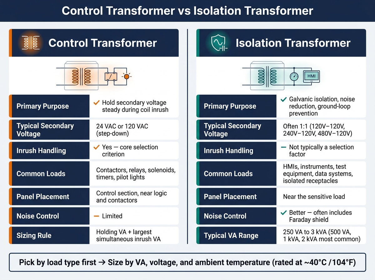
Control Transformer vs Isolation Transformer: Key Differences
Both use windings, and both can change voltage. But they’re built for different jobs.
A control transformer is meant to supply steady control power. An isolation transformer is picked mainly for galvanic isolation and noise reduction.
Once you strip it down, the choice comes down to three things: how the voltage behaves under load, what the transformer is powering, and where it sits in the panel.
| Feature | Control Transformer | Isolation Transformer |
|---|---|---|
| Purpose and safety role | Control-circuit reliability; isolation is a byproduct | Chosen mainly for separation, noise control, and ground-loop reduction |
| Typical secondary voltage | 24 VAC or 120 VAC (step-down) | Often 1:1, but step-up/step-down versions exist |
| Regulation under inrush | Sized to hold voltage during coil inrush | Not typically selected for inrush performance |
| Common loads | Contactors, relays, solenoids, pilot devices, timers | Instrumentation, test equipment, isolated receptacles, sensitive electronics |
| Best-fit application | Coil-heavy control circuits needing dependable low-voltage output | Loads needing separation, lower noise, or ground isolation |
Secondary Voltage and Regulation
Control transformers are sized to hold voltage during coil inrush. That matters because coils can pull a higher current at startup, and a weak transformer can let the secondary voltage sag right when the circuit needs it most.
Isolation transformers usually serve a different role. They’re often sized for 1:1 separation, where the main goal is electrical separation, not inrush handling. Step-up and step-down versions exist, but voltage change is usually secondary to that job.
Safety Role and Typical Loads
A control transformer gives you isolation as part of supplying usable control power. An isolation transformer is chosen more directly for separation, noise control, and ground-loop reduction.
Control transformers fit loads like contactor coils, relay coils, solenoids, timers, and pilot devices. These loads switch often and can draw inrush current, so voltage hold-up matters.
Isolation transformers fit loads like instrumentation, data acquisition gear, test equipment, isolated receptacles, and sensitive electronics. These loads benefit from cleaner separation and lower electrical noise.
Where Each Transformer Fits in a Panel
Panel placement usually follows purpose.
Control transformers belong in the control section, close to the contactors, relays, and logic they power. Isolation transformers belong near the load they serve, such as an HMI, a test point, an isolated receptacle, or a sensitive instrument circuit.
Put simply: control transformers sit with the control hardware, while isolation transformers sit beside the load they’re meant to separate.
Those differences shape which transformer makes sense for a given panel.
How to Choose the Right Transformer
Now that the transformer types are clear, narrow your choice by looking at voltage, load type, and ambient temperature. Before you pick anything, verify the primary voltage, secondary voltage, total VA, and the ambient temperature around the unit.
Choose a Control Transformer for Coil-Heavy Loads
If your panel runs contactors, relay coils, solenoid valves, pilot lights, or timers, go with a control transformer. The sizing rule is pretty simple: calculate the holding VA and add the largest inrush load that can happen at the same time. Then move up to the next standard VA rating.
Also check the ambient temperature before you lock in the selection. Many transformer ratings assume about a 40 °C maximum ambient. If the enclosure runs hot or airflow is tight, derate the transformer or step up to the next size.
Choose an Isolation Transformer When Separation Comes First
For instrumentation, industrial PCs, data acquisition systems, test benches, or isolated panel receptacles, an isolation transformer usually makes more sense. Start by confirming the input voltage, output voltage, and the required isolation level. After that, size it for continuous VA and leave some headroom for future loads.
With electronic loads, inrush is often limited, so thermal rating and insulation class tend to matter more than inrush.
The practical rule is simple: pick by load type first, then size by VA.
Conclusion: The Short Answer
Use a control transformer for coil-heavy circuits. Use an isolation transformer for separated, low-noise power. Use both when one panel has to handle both jobs.
FAQs
Can one transformer do both jobs?
No. An autotransformer uses one shared winding to change voltage, which creates a direct conductive path between the input and output. That means it does not provide electrical isolation.
An isolation transformer uses separate primary and secondary windings to provide galvanic isolation. That physical separation can help block electrical noise, lower shock risk, and make independent grounding possible.
How do I size a control transformer correctly?
Start by calculating the total connected load. For single-phase systems, use kVA = (Voltage × Current) / 1,000. For three-phase systems, use kVA = (1.732 × Voltage × Current) / 1,000.
From there, apply diversity factors, then add a 20% to 25% margin for continuous operation and possible inrush current. After that, round up to the nearest standard NEMA kVA rating.
A good rule of thumb is to keep the load within the 60% to 80% capacity range. That gives you room to operate without pushing the unit too hard.
Do I need a shielded isolation transformer?
Use an isolation transformer only when you need to keep electrical noise or transients away from sensitive low-power equipment, or when you need controlled grounding and separation on the secondary side.
A standard isolation transformer provides full galvanic separation. A shielded isolation transformer adds a Faraday shield that sends high-frequency noise to ground, which helps with common-mode noise rejection.
If your goal is just simple voltage conversion without isolation, you usually don’t need one.