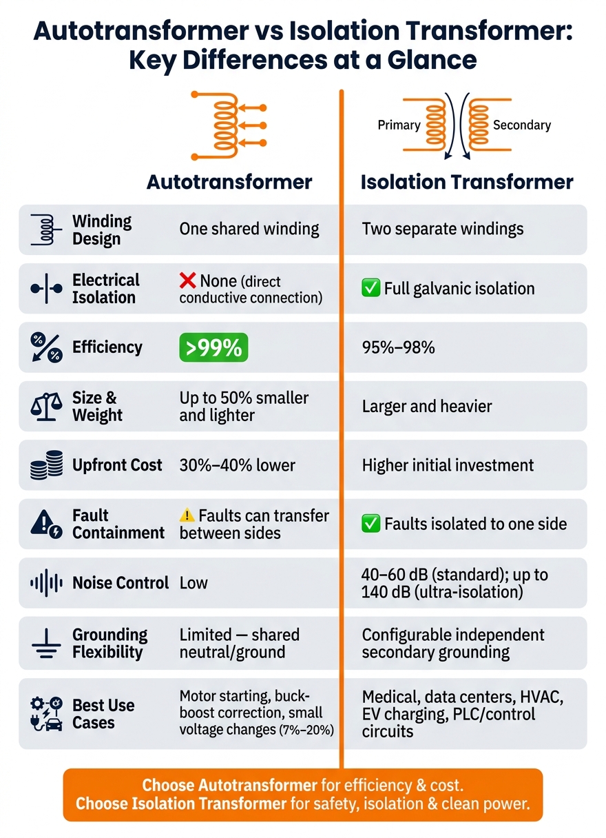
Autotransformers vs Isolation Transformers: Key Differences
If you need isolation, grounding control, or cleaner power, I’d pick an isolation transformer. If I only need a small voltage change and want lower cost, smaller size, and very high efficiency, I’d pick an autotransformer.
Here’s the short version:
-
Autotransformer
- One shared winding
- No electrical isolation
- Best for small voltage changes, often around 7% to 20%
- Often 30% to 40% less expensive
- Can be up to 50% smaller and lighter
- Efficiency can exceed 99%
-
Isolation transformer
- Two separate windings
- Full galvanic isolation
- Better for fault separation, noise control, and new grounding reference
- Often used where a separately derived system is needed
- Typical efficiency is about 95% to 98%
- Common-mode noise rejection is often 40–60 dB, and much higher with shielded units
What matters most is simple: an autotransformer connects source and load directly, while an isolation transformer keeps them electrically separate. That one design difference affects shock risk, grounding, fault path, noise, size, and price.
Quick Comparison
| Criteria | Autotransformer | Isolation Transformer |
|---|---|---|
| Winding design | One shared winding | Two separate windings |
| Electrical isolation | No | Yes |
| Grounding options | Limited | More control on the secondary |
| Fault transfer | Faults can pass between sides | Faults stay on one side |
| Noise control | Low | Better, especially with shielding |
| Best use | Small voltage correction, motor starting, buck-boost | Sensitive loads, medical, controls, EV, HVAC |
| Efficiency | >99% | 95%–98% |
| Cost | Lower | Higher |
| Size and weight | Smaller | Larger |
If I were making the call, I’d use autotransformers for efficiency and cost, and isolation transformers for safety, grounding, and cleaner power.
Autotransformer vs Isolation Transformer: Key Differences at a Glance
Autotransformers: How They Work, Where They Fit, and Their Limits
How the Single-Winding Design Works
An autotransformer uses one winding with taps to set the output voltage. The input and output share part of that same winding, which means power moves in two ways: through magnetic induction and directly through the shared winding. That's the key idea behind the design.
Because of that shared path, autotransformers are a better fit for small voltage changes than for isolation. If you need one circuit separated from another, this isn't the tool for the job.
The single-winding setup uses less copper and iron, so the unit is smaller and often more efficient than an isolation transformer with the same kVA. It works best when the source and load voltages are close, like 480V to 415V. In most cases, the best use case is a small voltage correction, usually in the 7% to 20% range. When the voltage step is smaller, more of the winding serves as a common path, which cuts the amount of copper and iron needed.
There's a tradeoff, though. Since the circuits are tied together through that shared winding, faults, surges, and noise can pass directly between them.
Where Autotransformers Are a Good Fit
Autotransformers make sense for motor starting, buck-boost correction, and industrial loads that don't need isolation.
For motor starting, taps at 50%, 65%, or 80% of line voltage help limit inrush current while the motor accelerates. For voltage correction, buck-boost units wired in the field as autotransformers handle small adjustments to match the supply voltage to the equipment nameplate rating.
That said, there are clear limits. A winding failure or a lost neutral can expose the load to primary voltage. So if a ground fault, surge, or neutral problem can't be allowed to pass from one side to the other, an autotransformer is the wrong fit.
When separation, grounding control, or noise suppression matter, the next section shows why a separate-winding design makes more sense.
sbb-itb-501186b
Isolation Transformers: Separate Windings, Safety, and Noise Control
How Galvanic Isolation Changes Performance
Unlike the shared-winding design above, an isolation transformer keeps the source and load apart. It does this with separate primary and secondary windings, which creates galvanic isolation - a complete electrical break between source and load. Put simply, the load current is induced magnetically instead of being carried straight from the source.
That isolated secondary can also use its own grounding reference. This helps create a stable neutral-to-ground bond in HVAC controls, EV charging, and other loads where code rules matter.
In many cases, isolation transformers are used in a 1:1 setup when the main goal is separation rather than voltage conversion. They also work well for larger voltage changes, such as 480V to 120V, when the application needs a new grounded secondary.
Where Isolation Transformers Are Preferred
The same separation that helps with grounding also improves noise control. It can block common-mode noise, ground loops, and high-frequency transients before they reach downstream equipment. Standard units usually provide 40–60 dB of common-mode rejection. Shielded versions can reach 80–120 dB, and ultra-isolation models can exceed 140 dB. A Faraday shield helps by diverting capacitive noise to ground before it reaches the load.
That kind of noise rejection makes isolation transformers a strong fit for medical patient care areas, laboratories, PLC and control circuits, and data environments. In medical settings, the isolated secondary can reduce shock risk when the system is installed and grounded correctly. In industrial control panels, the separation helps protect PLCs from upstream transients. And in facilities that run variable frequency drives, K-rated isolation transformers - K-4, K-13, and K-20 - are built to handle the extra heat caused by non-linear loads.
The downside is pretty simple: lower efficiency, higher cost, and a larger footprint. Those tradeoffs stand out more clearly in the side-by-side comparison that follows.
Autotransformer vs Isolation Transformer: Side-by-Side Comparison
Design, Safety, and Grounding Differences
The tradeoffs are much easier to see when you put both transformer types next to each other.
The big split is simple: an autotransformer ties the source and load together, while an isolation transformer keeps them apart. That one design choice shapes safety, grounding, and fault behavior. Since an autotransformer uses a shared winding, a fault on the primary side can reach the secondary. Under the NEC, that matters when the design calls for a separately derived system with its own grounded secondary.
| Feature | Autotransformer | Isolation Transformer |
|---|---|---|
| Winding Design | Single shared winding | Separate primary and secondary windings |
| Electrical Isolation | None - direct conductive connection | Full galvanic isolation |
| Grounding | Shared neutral/ground reference; limited flexibility | Configurable; independent secondary grounding |
| Fault Containment | Faults can transfer between sides | Faults are isolated to one side |
| Shock Protection | Lower; direct path to source | Higher; limits earth-contact risk |
Efficiency, Footprint, and Cost Differences
On the practical side, autotransformers usually win on size, weight, and price.
They’re smaller, lighter, and less expensive. Efficiency can top 99%, while most isolation transformers land in the 95% to 98% range. Upfront cost is also 30% to 40% lower at the same kVA rating. If you’re dealing with a tight electrical room or trying to trim project spend, that gap can be hard to ignore.
| Aspect | Autotransformer | Isolation Transformer |
|---|---|---|
| Typical Efficiency | >99% | 95%–98% |
| Size & Weight | Up to 50% smaller and lighter | Larger and heavier |
| Upfront Cost | 30% to 40% lower | Higher initial investment |
| Voltage Regulation | Excellent - lower impedance | Good - higher impedance |
Application Fit by Load Type
The right pick depends on the load. That’s where this stops being theory and starts becoming a design call.
Autotransformers make sense when you need efficient voltage adjustment and don’t need isolation. Isolation transformers fit loads where shock reduction, grounding control, or cleaner power matter more.
| Load Type | Recommended Type | Reason |
|---|---|---|
| Motor starting | Autotransformer | Reduces inrush current cost-effectively |
| Industrial heating elements | Autotransformer | Precise voltage control; no isolation needed |
| Small voltage correction | Autotransformer | Efficient for small ratio adjustments |
| Sensitive electronics / data centers | Isolation Transformer | Noise reduction and transient protection |
| Healthcare facilities / patient care areas | Isolation Transformer | Shock risk reduction and isolation |
| HVAC installations and EV charging stations | Isolation Transformer | Separately derived system requirements |
That load-by-load split sets up the selection checklist below.
How to Choose the Right Transformer and Where to Source It
A Practical Selection Checklist
After you compare design and performance, run through four simple checks to pick the right unit:
- Need galvanic isolation or a separately derived system? Choose an isolation transformer.
- Need only a modest voltage change? Choose an autotransformer.
- Need noise and ground-loop control? Choose an isolation transformer.
- Need the smallest, lightest, lowest-cost option? Choose an autotransformer.
This is where the decision gets pretty simple. If safety separation, grounding control, or cleaner power matters most, go with isolation. If your main goal is a small voltage adjustment in a lighter, lower-cost package, an autotransformer usually makes more sense.
Using Electrical Trader to Match Specs to Listings
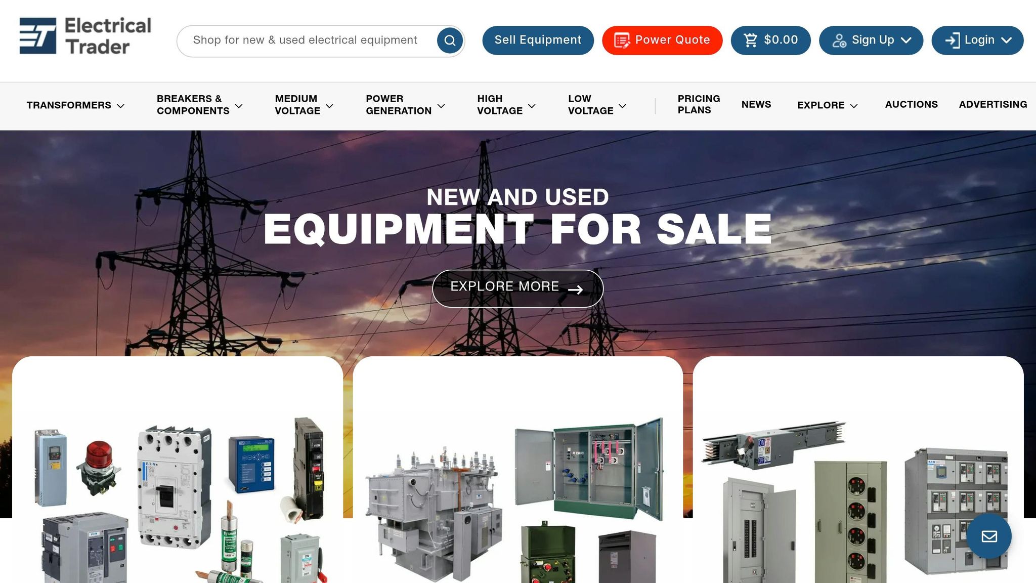
Once you know the transformer type, the next step is matching your spec to live listings. Electrical Trader is one place to source transformers.
When you search, filter by kVA, primary voltage, secondary voltage, and winding type. Use "two-winding" for isolation transformers and "single-winding" for autotransformers. That helps you line up the unit with the application and safety-code requirements before equipment ships.
Conclusion: Isolation or Efficiency - The Core Decision
Autotransformers come out ahead on size, efficiency, and cost. Isolation transformers come out ahead on isolation, grounding control, and noise rejection. The smart move is to match the transformer to the load's needs, not just the lowest price.
Autotransformer Versus Isolation Transformer Explained Simply
FAQs
When should I choose an isolation transformer over an autotransformer?
Choose an isolation transformer when your application calls for safety-critical operation, lower noise, or tight grounding control.
It provides complete electrical separation, which makes it the better fit for protecting sensitive electronic equipment from voltage transients and high-frequency noise, meeting strict safety standards or electrical codes, and dealing with large voltage differences or systems that need an independent grounding reference.
Is an autotransformer safe for sensitive equipment?
No. An autotransformer is usually not a safe pick for sensitive equipment because it uses a shared winding and does not provide electrical isolation.
Here’s the plain-English version: the input and output are tied together through the same winding. So input-side noise, surges, and faults can pass straight through to the equipment. And if the winding fails, the equipment could be exposed to the full input voltage.
For sensitive systems, an isolation transformer is the right choice.
Does an isolation transformer always need a new ground reference?
No. An isolation transformer does not always need a new ground reference, but it does give you the option to set one up if you need it.
Because the primary and secondary windings are electrically separate, the secondary side can be left ungrounded. Or, you can ground the secondary neutral to create a clean earth reference. That gives you more flexibility than an autotransformer, which shares the primary-side ground reference.