How to Select Autotransformers for Industrial Use
Autotransformers are compact, efficient solutions for adjusting voltage in industrial environments. They help machinery operate on different voltage levels, manage motor inrush currents, and reduce energy losses. However, their lack of electrical isolation requires careful consideration of grounding and safety measures.
Here’s how to select the right autotransformer:
- Match Voltage and Frequency: Ensure primary and secondary voltage ratings align with your facility's supply and equipment needs. Confirm the frequency (50 Hz or 60 Hz) matches your system.
- Calculate kVA or Ampacity: Use the correct formula for single-phase or three-phase systems. Account for motor inrush by oversizing by 25% and adding a safety margin.
- Choose Winding Material: Copper is ideal for corrosive or humid environments, while aluminum suits dry, controlled settings.
- Select Core Type and Cooling: Laminated cores work for most industrial setups. Ensure proper cooling to prevent overheating.
- Review Additional Specs: Check voltage taps, operating temperature, and impedance to avoid performance issues.
Carefully sizing and specifying your autotransformer ensures efficiency, safety, and longevity. For reliable options, explore trusted brands like Siemens, ABB, and GE.
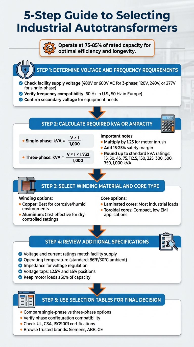
5-Step Guide to Selecting Industrial Autotransformers
Autotransformer Basics
What Are Autotransformers?
An autotransformer uses a single tapped winding to handle both primary and secondary functions, allowing for voltage adjustments by connecting the load or source to different tap points.
The power transfer in an autotransformer happens in two ways: part of it is transferred inductively through the shared winding, while the rest flows directly through the series winding. This dual transfer mechanism allows for a smaller magnetic core compared to an isolation transformer of the same power rating. As a result, autotransformers are more compact, lighter, and less expensive to produce since they require less copper and iron.
These design characteristics make autotransformers distinct from isolation transformers in several important ways.
Autotransformers vs Isolation Transformers
Unlike autotransformers, isolation transformers use separate windings to maintain complete electrical separation between the input and output circuits. In contrast, autotransformers share a common winding, which affects their performance and applications.
This shared winding design has its pros and cons. Autotransformers are more compact and efficient for the same power rating, with lower impedance that results in better voltage regulation. However, they do not provide electrical isolation, meaning they cannot block electrical noise or surges between circuits. Additionally, if the winding fails, connected equipment may be exposed to the full input voltage.
| Feature | Autotransformer | Isolation Transformer |
|---|---|---|
| Winding Design | Single continuous winding with taps | Separate primary and secondary windings |
| Electrical Isolation | None - shared winding | Complete electrical isolation |
| Size & Weight | Smaller and lighter | Larger and heavier |
| Efficiency | Higher | Lower due to higher impedance |
| Best Use Case | Small voltage adjustments | Safety-critical or noise-sensitive setups |
Autotransformers are most effective for voltage adjustments within a 3:1 ratio. For larger voltage differences, isolation transformers are generally safer and more practical, especially in industrial environments.
Beyond these design differences, autotransformers also vary based on their phase configuration, which determines their suitability for specific applications.
Single-Phase vs Three-Phase Autotransformers
The choice between single-phase and three-phase autotransformers depends on the power demands and setup of your equipment.
Single-phase autotransformers are ideal for lower-power applications. They are commonly used in laboratories (as variable autotransformers or Variacs), for voltage conversion in international devices, and for adapting small machines to different power supplies. Their straightforward installation makes them a go-to option for single-phase systems.
Three-phase autotransformers are essential for industrial applications. They play a key role in interconnecting power grids, soft-starting large motors, and managing voltage drops over long distances. Some larger three-phase models include a "buried" delta winding to reduce harmonic currents, as standard autotransformer designs do not naturally suppress these.
When deciding between single-phase and three-phase autotransformers, consider the power configuration of your facility and the equipment you're running. Three-phase systems are the standard in most industrial settings because they handle higher power loads and operate more efficiently with heavy machinery and motors.
sbb-itb-501186b
Step 1: Determine Voltage and Frequency Requirements
Check Your Facility's Supply Voltage
The first step is to identify your facility's primary (supply) voltage, which must align with the autotransformer's rated input voltage. This primary voltage is the power supplied by your utility or local power source, and matching it correctly ensures the autotransformer operates effectively.
Industrial facilities typically use 480V or 600V AC for three-phase systems, while single-phase systems often rely on 120V, 240V, or 277V. Below is a table listing common voltage ratings for both single-phase and three-phase systems:
| Phase Type | Common Voltage Ratings (Primary) |
|---|---|
| Single Phase | 100V, 110V, 115V, 120V, 200V, 208V, 220V, 230V, 240V, 277V, 347V, 380V, 400V, 416V, 440V, 460V, 480V, 550V, 575V, 600V |
| Three Phase | 100V, 110V, 115V, 120V, 190V, 200V, 208V, 216V, 220V, 230V, 240V, 380V, 400V, 416V, 440V, 460V, 480V, 550V, 575V, 600V |
To confirm your facility's voltage, check the electrical panel or consult wiring diagrams. It's also a good idea to measure the actual voltage at the service point rather than relying solely on standard ratings. Additionally, you'll need to determine the secondary voltage, which is the specific voltage your equipment - such as motors or heaters - requires to operate.
Once you've identified the voltage requirements, ensure that the supply frequency also matches your equipment's specifications.
Verify Frequency Compatibility
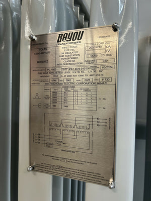
The next step is to confirm that the frequency of your power supply, measured in Hertz (Hz), matches both the autotransformer and the equipment it will power. In the U.S., the standard frequency is 60 Hz, while in Europe and many other regions, it's 50 Hz.
Modern industrial autotransformers are often dual-rated for 50 Hz and 60 Hz, making them adaptable to global power systems. This flexibility is especially helpful if your facility uses equipment sourced from different regions or if you're setting up international installations. To avoid issues like inefficiency, overheating, or equipment damage, always check the autotransformer's nameplate or product specification sheet to confirm its frequency rating before purchase.
Ensuring proper voltage and frequency alignment is critical to the safe and efficient operation of your equipment.
Step 2: Calculate the Required kVA or Ampacity
Load Calculation Formula
To determine the kVA rating needed for your autotransformer, use the correct formula based on whether your system is single-phase or three-phase.
For single-phase systems, the formula is straightforward:
kVA = (V × I) / 1,000
Here, V represents the load voltage, and I is the load current. For example, if your load operates at 240 volts and draws 150 amps, the calculation would be:
(240 × 150) / 1,000 = 36 kVA.
For three-phase systems, the formula changes slightly to account for the square root of 3 (approximately 1.732):
kVA = (V × I × 1.732) / 1,000
If you’re working with a 480-volt system carrying 200 amps, the calculation would be:
(480 × 200 × 1.732) / 1,000 ≈ 166.3 kVA.
If your load is measured in kilowatts (kW) instead of amperes, you’ll need to convert it to kVA by factoring in the power factor (PF):
kVA = kW / PF
Avoid assuming that kW and kVA are interchangeable - ignoring the power factor can lead to overheating issues.
For unbalanced three-phase loads, always size the transformer based on the phase with the highest current demand, not the average across all three phases. This prevents overloading the most heavily burdened phase.
Once you’ve determined the base kVA, be sure to adjust for motor startup demands.
Account for Motor Inrush and Oversizing
Motors can draw up to six times their normal running current during startup. This surge, known as inrush current, can overload an autotransformer that’s only sized for steady-state operation.
To account for this, multiply your calculated kVA by 1.25 to handle motor inrush. Afterward, add a safety margin of 15–25% - choose 15–20% for standard applications and 25–30% for critical or future-expandable setups.
"In most cases, you'll want to select a transformer with a rating slightly higher than the kVA you calculated." - Todd Benadum, ELSCO
After applying these adjustments, round up to the nearest standard kVA rating. Common industrial transformer sizes include:
15, 30, 45, 75, 112.5, 150, 225, 300, 500, 750, and 1,000 kVA. For instance, if your final calculation comes to 52.5 kVA after adding safety margins, select a 75 kVA transformer. Operating a transformer at 75% to 85% of its rated capacity ensures better efficiency, longer life, and room for load fluctuations.
If motor inrush remains a concern, consider solutions like soft starters, Variable Frequency Drives (VFDs), or implementing staggered motor start sequences to reduce the surge. Additionally, for facilities with numerous VFDs or sensitive electronic equipment, it’s wise to add an extra 10–15% capacity to compensate for harmonic-related losses.
Careful calculation at this stage is essential before moving on to evaluate material and core specifications in the next step.
Auto Transformers Explained: Working Principle, Wiring & Construction Guide
Step 3: Select Winding Material and Core Type
Once you've determined the correct size for your transformer, the next step is choosing the right winding material and core type. These choices directly impact the transformer's performance, durability, and cost-effectiveness in industrial settings.
Copper vs. Aluminum Windings
The material used for windings plays a big role in a transformer's efficiency and longevity. Copper windings are known for their excellent conductivity and resistance to corrosion, making them a better choice for environments with high humidity or exposure to corrosive elements. This includes places like coastal regions, chemical plants, or marine applications.
"The primary advantage of copper is its superior corrosion resistance. Copper wound transformers are commonly used for corrosive or high humidity environments like marine applications." – TEMCo Industrial
On the other hand, aluminum windings are a more budget-friendly option and perform well in dry, controlled environments. They are typically found in three-phase configurations. For single-phase setups, copper is generally the preferred material. However, in three-phase systems where cost is a significant factor and the environment is dry, aluminum can be a practical alternative.
Core Type and Cooling Methods
The type of core you choose depends on the application. Laminated cores are widely used for industrial loads and are designed to work with passive cooling systems, such as ventilated enclosures like NEMA 3R. For applications requiring a compact design and reduced electromagnetic interference - such as certain medical-grade equipment - toroidal cores are a suitable option.
Proper cooling is essential to prevent heat buildup caused by losses in the core and windings. If a transformer operates beyond its current rating, it could lead to insulation failure or shorts. In environments with high temperatures, transformers with Class 220 insulation are better equipped to handle prolonged thermal stress. Additionally, when accommodating motor loads, it's recommended to avoid exceeding 60% of the transformer's maximum capacity.
Step 4: Review Additional Specifications
Once you've settled on the right size and materials, it's time to focus on the finer details that ensure your autotransformer operates safely and efficiently.
Voltage and Current Ratings
The transformer's voltage ratings must align with your facility's power supply. For example, primary voltage options often include 120V, 240V, 480V, and 600V. The secondary voltage, determined by the tap point and turns ratio, should also meet your operational needs. While it's okay to choose a transformer with a slightly higher capacity for industrial loads, undersizing is a strict no-go. Always refer to the wiring diagram to confirm compatibility.
Operating Temperature and Impedance
Standard ratings in the U.S. assume an average ambient temperature of 86°F (30°C) over a 24-hour period. If your facility's environment exceeds this temperature, you'll need to "de-rate" the transformer, meaning it won't be able to operate at full capacity. Electrical engineer David Castor explains:
"If the average ambient exceeds 30 deg C, it has to be de-rated".
Impedance is another critical factor to consider. While lower impedance improves voltage regulation, it can also lead to inrush currents up to 20 times the full load, potentially tripping breakers if not accounted for. To ensure accuracy during short-circuit calculations, always check the nameplate for the temperature at which impedance was measured - usually around 170°C.
Voltage Taps for Adjustment
Voltage taps are designed to fine-tune the output by adjusting a small percentage of the primary winding. Most off-circuit tap changers offer five positions: ±2.5% and ±5%. These adjustments are especially helpful if your facility is located far from the utility substation, where supply voltage can often deviate from nominal levels.
However, improper use of these taps can cause issues. Jon from Electric Motor Research cautions:
"Changing the taps... (using the 432V tap supplied with 504V) will operate the transformer at higher than its designed volts/turn. This will increase magnetic saturation and core loss, and might result in a distorted output waveform".
Before deciding on a tap setting, measure your incoming voltage carefully. Remember, off-circuit taps can only be adjusted when the transformer is fully de-energized.
Step 5: Use Selection Tables to Make Your Final Decision
Compare Single-Phase and Three-Phase Options
Selection tables are a handy way to compare options side by side, especially when deciding between single-phase and three-phase autotransformers. Start by identifying the primary voltage category to narrow down your choices.
Here’s a quick breakdown of the main differences:
| Feature | Single-Phase Autotransformer | Three-Phase Autotransformer |
|---|---|---|
| Common Voltages | 120 V, 240 V, 480 V | 208 V, 240 V, 480 V, 600 V |
| Winding Material | Typically copper only | Copper or aluminum |
| Typical Applications | Small machinery, lighting, heating | Industrial motors, HVAC, large-scale manufacturing |
| Efficiency | High (shared winding) | Very high (reduced energy losses) |
| Cost | Lower for small voltage ratios | Economical for large industrial loads |
It’s essential to confirm that the phase configuration of the autotransformer aligns with your equipment. This ensures compatibility and optimal performance.
Harold Williams, Associate Editor at Electricity Forum, explains:
"Autotransformers stand out for their efficiency, as the shared winding reduces energy losses and improves performance."
Once you’ve compared the options, you’re ready to dive into detailed listings to find the right match.
Visit Electrical Trader for Autotransformer Listings
After evaluating your options, head over to Electrical Trader to explore available models. The platform makes it simple to search by primary voltage and capacity, with filters to refine your results further. You’ll find models from well-known brands like Siemens, ABB, and GE. For instance, the HPS Sentinel G 75 kVA (3 Phase) is listed at $2,499.00, while other three-phase transformers start around $4,000.00. Adjust your search by voltage, capacity, or voltage taps to pinpoint the best option for your needs.
Conclusion
To choose the right autotransformer for your industrial needs, follow these steps carefully. Match the voltage and frequency requirements, calculate the kVA capacity, and pick the appropriate winding material. Keep motor loads at no more than 60% of the transformer's capacity to handle startup currents effectively and prevent overheating.
Once the sizing is determined, prioritize material quality to ensure durability. Copper windings are ideal for environments with high humidity or near marine areas due to their resistance to corrosion, while aluminum windings are a budget-friendly option for standard industrial applications. Always verify that the product complies with UL, CSA, and ISO9001 standards for safety and performance.
Check wiring compatibility by referring to the product documentation. For dry locations, opt for NEMA 3R ventilated enclosures with well-designed cooling ducts to promote natural air circulation, which helps extend the lifespan of the internal coils.
You can find reliable autotransformers from trusted manufacturers like Siemens, ABB, and GE on Electrical Trader. Their platform offers filters for voltage, capacity, and category, making it easier to narrow down your options.
Investing time in evaluating these factors upfront can help you avoid unnecessary downtime and costly equipment replacements later.
FAQs
When should I choose an isolation transformer instead of an autotransformer?
When electrical isolation is necessary for safety, minimizing noise, or avoiding ground loops, an isolation transformer is the right choice. It offers galvanic isolation, which helps protect against electric shock, cuts down on interference, and safeguards sensitive equipment. On the other hand, an autotransformer, which uses shared windings for primary and secondary circuits, is a more budget-friendly option for situations where isolation isn't required.
How do I size an autotransformer for motor starting and inrush current?
When determining the right size for an autotransformer to handle motor starting and inrush current, you’ll need to account for the motor’s starting current. This is generally 6–8 times the motor’s full load current (FLC). To ensure the transformer can manage this surge effectively, select a unit with a capacity that includes a safety margin - typically around 25% - to cover any unexpected variations. Additionally, make sure the transformer provides adequate voltage regulation to avoid significant dips during startup. This helps maintain reliable operation and extends the lifespan of your equipment.
What safety and grounding steps are required since there’s no electrical isolation?
Autotransformers don’t provide electrical isolation, which makes safety measures and proper grounding absolutely critical to avoid shock hazards. Here’s how to ensure safe operation:
- Ground the autotransformer: Always connect its frame and secondary circuit to a grounded system to reduce the risk of electrical faults.
- Install protective devices: Use fuses, circuit breakers, and grounding conductors to safeguard against overloads and potential failures.
- Follow proper wiring standards: Make sure all connections comply with local electrical codes to ensure safe and reliable operation.
Routine inspections are also important to keep everything working safely and in line with regulations.