




How BAS Sensors Improve HVAC and Lighting
Bad sensor data leads to bad control. If I place sensors well, match them to the right input, and keep wiring and logic clean, I can cut comfort issues, trim waste, and help HVAC and lighting respond to actual room conditions.
Here’s the short version:
- Temperature, humidity, pressure, airflow, and CO2 sensors guide HVAC control.
- Occupancy and daylight sensors tell lighting when to switch or dim, and they can also help HVAC trim runtime.
- Placement matters as much as sensor type. A room sensor near a diffuser, window, or door can be off by 2–4°F.
- CO2 sensors for DCV should meet ±75 ppm at 600 and 1,000 ppm and usually should not need recalibration more than every 5 years.
- Space temperature sensors often work best on interior walls 4–5 ft above finished floor.
- CO2 sensors usually belong 3–6 ft above the floor in the occupied zone.
- Low-voltage BAS wiring should stay away from 120 V, 208 V, and 480 V power wiring, with about 12 in. of separation when physical spacing is limited.
- Buildings with tuned controls often use 10–30% less energy, and tied occupancy/daylight logic can help deliver 12–17% HVAC energy savings.
What this means for you is simple: pick the right sensor, put it in the right spot, and keep the sequence easy to follow. If I get those three things right, the BAS has a much better shot at keeping spaces comfortable and equipment from running longer than needed.
Before I get into the full article, that’s the core takeaway: accurate inputs, clean placement, and simple control logic are what make HVAC and lighting work the way they should.
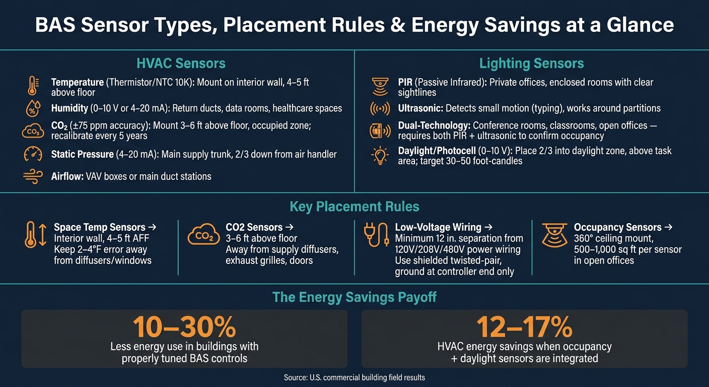
BAS Sensor Types, Placement Rules & Energy Savings at a Glance
Building Automation System Input Sensors
sbb-itb-501186b
Choose the Right BAS Sensor for the Job
Each BAS sensor needs to line up with the control point, signal range, and sensing method the controller is built to read. If the input is wrong, the result is usually messy: unstable control, comfort complaints, and wasted energy. Once the control point is set, the next step is simple in theory but important in practice: pick the sensor type and signal the controller can actually use.
HVAC Sensors: Temperature, Humidity, Pressure, Airflow, and CO2
Space temperature sensors are the BAS input you’ll see most often. A common option is a 10K NTC thermistor, which changes resistance as temperature shifts. The controller reads that resistance and converts it into a temperature value with a built-in curve. Duct temperature probes work the same way and are used to track mixed air, discharge air, or coil leaving temperature.
Humidity sensors use capacitive or resistive elements and send a 0–10 V or 4–20 mA signal based on relative humidity. They’re common in data rooms, healthcare spaces, large open offices, and return ducts where moisture control matters. Static pressure sensors and differential pressure transmitters send duct pressure data back to the fan’s variable frequency drive (VFD) for static pressure reset. Airflow sensors may be built into VAV boxes or added as dedicated airflow stations in main ducts or outdoor air intakes to verify ventilation.
CO2 sensors support demand-controlled ventilation (DCV) in spaces where occupancy changes through the day, like conference rooms, classrooms, and open offices. ASHRAE Standard 62.1 requires CO2 sensors used for DCV to be accurate within ±75 ppm at 600 and 1,000 ppm, factory-calibrated, and not needing recalibration more often than every 5 years. When a CO2 sensor drifts, the system can over-ventilate or under-ventilate the space. That hits comfort and energy use at the same time.
Lighting Sensors: Occupancy and Daylight Inputs
PIR (passive infrared) sensors detect motion by sensing changes in infrared radiation. They fit private offices and enclosed rooms with a clear line of sight, but they can miss someone who stays still at a desk. Ultrasonic sensors send out high-frequency sound waves and detect movement through changes in the reflected waves. They can catch small motions like typing and work around partitions, but they’re more likely to false-trigger from air movement or mechanical noise. Dual-technology sensors combine both methods and require both to confirm occupancy, which cuts false positives. That makes them a solid fit for conference rooms, classrooms, and open offices where nuisance shutoffs tend to create the most complaints.
Daylight sensors and photocells measure available natural light and send a proportional analog signal, usually 0–10 V, to the controller. The BAS compares that reading to a target illuminance level, usually 30–50 foot-candles in offices, and then dims or switches circuits to match. When occupancy status is shared, lighting and HVAC can react to the same room condition.
BAS Signal Types and Connected Hardware
Signal type plays a big role in accuracy and noise resistance. Thermistor resistance inputs are simple and low-cost, but long cable runs can add resistance and throw off the reading. 0–10 V analog signals are common for humidity, pressure transmitters, and lighting dimming, though they’re more exposed to electrical noise over longer distances. 4–20 mA current loops are a better fit for long runs or electrically noisy spaces, which is why they’re often used for duct static pressure and differential pressure across filters. Dry contacts handle binary inputs such as occupied/vacant status from occupancy sensors. BACnet digital points allow one smart sensor to send temperature, humidity, and CO2 over a single network connection, which cuts down on analog inputs and adds diagnostic data.
From there, the controller drives the actuator, whether that’s a damper, valve, VFD, relay, contactor, or dimming driver. Then placement comes into play, because even the right sensor won’t help much if it isn’t reading the room or equipment the way it should.
Place Sensors Where They Reflect Actual Conditions
Sensor placement decides whether the BAS reads the space the way people feel it - or reacts to the wrong thing. After you pick the right sensor type, the next job is simple: put it where it measures the occupied space, not the equipment nearby.
Room and Duct Sensor Placement
Mount space temperature sensors on interior walls 4 to 5 ft above finished floor, and keep them away from diffusers, return grilles, doors, windows, and direct sunlight. Exterior walls and nearby windows can push readings off by 2–4°F, which can kick off heating or cooling that the space doesn’t need. Put a sensor too close to a supply diffuser, and it may read supply air instead of room air. That can make the BAS overshoot and short-cycle the unit.
For duct sensors, install duct temperature probes about 5 ft downstream of coils, away from elbows, dampers, filters, and fans, with the sensing element centered in the duct. Air along the duct wall can skew the reading, so the sensing element should stay out of that boundary layer. Static pressure sensors should go in the main supply trunk, about two-thirds of the way down from the air handler, and away from branch takeoffs.
The same idea applies to occupancy and daylight sensors. Placement and coverage matter more than the hardware alone.
Occupancy, CO2, and Daylight Sensor Placement
Occupancy sensors need to see desks, seating areas, and work zones. If a sensor points only at the doorway, it can miss people who are sitting still. In open offices, overlapping 360° ceiling sensors that each cover about 500–1,000 sq ft help remove blind spots behind partitions and furniture.
CO2 sensors for demand-controlled ventilation should be mounted 3–6 ft above the floor in the occupied zone, away from supply diffusers, exhaust grilles, doors, and operable windows. Return-duct CO2 sensors are a poor fit for DCV because leakage and air mixing can distort the reading. In a conference room or classroom, a wall-mounted sensor in the main seating area gives a better read on occupied-space conditions.
Place daylight sensors above the primary task area, about two-thirds into the daylight control zone, and keep them out of direct window glare. A sensor too close to exterior glass reads raw daylight instead of the light level at the desk. The result? Fixtures dim or switch off before the work surface has enough light.
Low-Voltage Wiring Separation and Zone Mapping Before Installation
Keep low-voltage signal cable separate from 120 V, 208 V, and 480 V wiring. When you can’t separate them physically, leave at least 12 in of clearance from conductors serving motors, drives, or contactors. Use shielded twisted-pair cable for analog and communication runs, and ground the shield at one end only - usually at the controller - to avoid ground loops.
Once sensors are placed and wired the right way, the BAS has a much better shot at running clean control sequences. Before installation starts, mark HVAC zones, lighting groups, and sensor coverage and height on a floor plan. This step helps catch wiring and zoning mismatches early. It also helps to overlay manufacturer coverage diagrams on the plan so each sensor’s location, point, and zone line up before any wire goes in.
Once placement is right, the next step is tying each input to a clear control sequence.
Set Up BAS Control Sequences for HVAC and Lighting
Once the sensors are in place and wired, BAS logic turns those readings into equipment commands. The goal is simple: take sensor data and turn it into clear equipment actions without piling on extra logic that makes the system harder to run.
Build the Control Loop from Input to Output
Every BAS sequence follows the same basic path: sensor input → controller logic → equipment output. A space temperature sensor sends the room temperature to the controller. The controller compares that reading to the heating and cooling setpoints, applies a deadband to avoid short cycling, and then modulates the damper or valve as needed.
Lighting works much the same way. A photosensor measures work-plane light, and the controller dims fixtures to maintain the target level.
Once the controller can read each input and respond to it, you can start using occupancy and CO2 logic to trim runtime.
Use Occupancy, CO2, and Temperature Data to Cut Runtime
Most commercial HVAC sequences use three operating modes: occupied, standby, and unoccupied. In occupied mode, the system holds normal setpoints and ventilation. Standby mode relaxes setpoints and reduces outdoor air. Unoccupied mode uses setback temperatures and minimum ventilation.
For demand-controlled ventilation, use CO2 thresholds with a short delay so the system doesn't react to brief spikes. Economizer logic should run only when outdoor air can provide free cooling.
That same occupancy state can also control lighting, so both systems react together instead of acting like two separate setups.
Coordinate Lighting and HVAC Using Shared Occupancy Logic
Use one shared occupancy point that both systems read from the same source. When the state is occupied, lights turn on to a programmed level and HVAC shifts to full setpoints and ventilation. When the state moves to standby mode, lights dim and HVAC widens its deadband while dropping ventilation to minimums. In the unoccupied state, lights turn off except for egress circuits, and HVAC falls back to setback temperatures.
Using one shared occupancy point helps keep HVAC and lighting on the same schedule instead of drifting apart.
Common Sensor and Sequence Mistakes to Avoid
Even a well-designed BAS can fall short if sensors are placed poorly, sequences are written badly, or wiring work is messy. These problems usually don’t show up with a big warning light. Instead, they surface as comfort complaints, higher energy bills, and equipment that runs longer than it should. In the field, these are the issues that most often turn a solid design into weak day-to-day performance.
Fix Placement, Coverage, and Calibration Problems Early
One of the most common sensor mistakes is bad placement. A room temperature sensor mounted near a supply diffuser, exterior door, copier, or window will read a local condition instead of the average condition in the occupied space. That pushes the BAS to react to the wrong signal. On paper, everything can look normal - the sensor may sit right at setpoint - while people across the room are still too hot or too cold.
Coverage can cause the same kind of trouble. Using one sensor for a large open office, gym, or atrium usually isn’t enough. Conditions can vary too much across the space for a single point to tell the whole story. In large zones, it makes more sense to add sensors than to expect one device to represent the entire area.
Calibration drift is less obvious, but it can do just as much damage. A temperature sensor that is off by only a few degrees can quietly throw off comfort and runtime until someone finally traces the problem back to that point. During startup, compare each sensor to a calibrated handheld instrument. Then recalibrate or replace any sensor that reads outside ±2% of the reference value.
Once the sensor data is solid, the next trouble spot is control logic.
Keep Control Sequences Simple and Fail-Safe
Complex sequences often lead to wasted energy and outputs that fight each other. Two of the most common logic problems are simultaneous heating and cooling, and simultaneous economizer and mechanical cooling. Both issues are usually easy to spot in trend logs, yet they can sit there for months if no one reviews those logs on a regular basis.
Every sequence also needs a backup plan for sensor failure, and every manual override needs a timeout. Without a fallback, the system can end up running nonstop or shutting down fully. Neither outcome is acceptable. And if an override has no timeout, fans or lights can keep running far longer than intended, wiping out the energy savings built into the sequence.
After the logic checks out, the last big field review is wiring and power.
Check Wiring, Grounding, and Power Supplies, Transformers, Breakers, and Relays
Analog drift is often caused by wire noise rather than a bad sensor. The most common source is running low-voltage BAS signal cables too close to high-voltage circuits.
Power supply sizing is another issue that gets missed. If several 24 VDC sensors and controllers are fed by a supply that’s too small, voltage can sag when all devices are active. That can lead to intermittent dropouts, random resets, and readings that drift under load. During startup, check actual field voltages under full load - not just at the panel when only a few devices are connected.
Conclusion: Better Sensor Data Leads to Better BAS Performance
Good sensor data and clear control logic are what make HVAC and lighting systems work the way they should. Pick sensors that fit the actual job. Put them where they can read real conditions. Write sequences that are clear and fail-safe. Then check calibration and wiring before startup wraps up. Miss one of those steps, and the rest of the BAS ends up working around bad data.
The upside is easy to measure. Buildings with properly tuned controls typically use 10–30% less energy than similar buildings without a BAS. And when occupancy and daylight sensors are tied into HVAC sequences, U.S. commercial building field results show 12–17% HVAC energy savings.
The hardware behind those controls matters too. If BAS work calls for breakers, transformers, or distribution gear, Electrical Trader puts sourcing in one marketplace.
That’s what helps keep U.S. buildings comfortable, efficient, and reliable over the long haul.
FAQs
How do BAS sensors affect comfort and energy use?
BAS sensors help make buildings more comfortable while cutting energy use. They do this by feeding real-time data into automated controls.
For example, temperature, CO2, and occupancy sensors let HVAC and lighting respond to what’s happening in the building right now, instead of following fixed schedules. That matters. If a room is empty, lights can dim or switch off. If occupancy goes up, ventilation can increase to match demand.
This cuts wasted energy, keeps airflow in line with actual use, and can lower annual energy costs by 20% to 30%. Fault detection sensors, like vibration and current monitors, add another layer of control by spotting mechanical problems early, before they lead to comfort issues or poor system performance.
Which sensor placement mistakes cause the most problems?
Poor sensor placement gives the BAS bad data from the start. And when the data is off, comfort suffers, equipment can run longer than it should, and energy use can climb.
A few mistakes show up all the time. Temperature sensors often get placed too close to doors, radiators, supply diffusers, or spots with direct sunlight. That can skew the reading and make the system react to the wrong conditions.
CO2 sensors are another common trouble spot. Mounting them at the ceiling can lead to readings that don’t reflect what people in the room are actually breathing. For more accurate readings, CO2 sensors should be installed 3.5 to 5 feet above the floor, within the occupied zone.
How can shared occupancy data improve HVAC and lighting control?
Shared occupancy data helps BAS shift from fixed schedules to real-time, demand-based control, which can cut energy use by 10% to 15%.
Using data from PIR motion sensors, mm-wave sensors, or CO2 monitors, the system can adjust HVAC setpoints and lighting based on how rooms are being used at that moment. That means it doesn't keep heating, cooling, or lighting empty spaces for no reason.
It also cuts waste from off-hours operation and schedule drift, which is a common problem in buildings that still run on outdated timing rules.





