
Ultimate Guide to Transformer Sizing and Selection
When choosing a transformer, size matters. Picking the wrong size can lead to costly inefficiencies, overheating, or unnecessary energy waste. Here's what you need to know:
- Undersized transformers overheat, damage components, and cause outages.
- Oversized transformers waste energy and money due to higher no-load losses and upfront costs.
- The right transformer size ensures safe, efficient, and reliable power distribution while lowering lifecycle costs.
To size a transformer correctly:
- Calculate load requirements in kVA using voltage, current, and power factor.
- Apply safety margins for future growth and environmental factors like temperature and altitude.
- Consider harmonic distortion for non-linear loads like LED lighting or VFDs - use K-rated transformers if needed.
- Match voltage levels to your system and choose the right winding configuration (Wye or Delta).
Proper selection balances performance and cost while extending the transformer's lifespan.
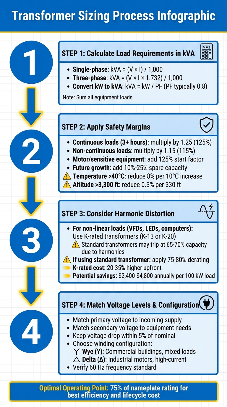
4-Step Transformer Sizing Process Guide
Transformer Size Calculation | Step by Step and Easy way
Transformer Basics and Specifications
This section dives into the essentials of transformers, offering a foundation for understanding their operation, specifications, and proper selection.
How Transformers Work
Transformers operate through electromagnetic induction, transferring energy from one circuit to another. When alternating current (AC) flows through the primary winding, it generates a magnetic flux in the core - typically made of laminated silicon steel or amorphous metal. This flux induces a voltage in the secondary winding, enabling energy transfer. The windings, made of insulated copper or aluminum, carry the current, while insulation materials like enamel, oil-impregnated paper, or synthetic fluids prevent electrical arcing.
To manage heat, transformers use cooling systems. Dry-type transformers rely on ambient air, while oil-filled units use liquids to dissipate heat. Most distribution transformers achieve efficiency rates between 98% and 99%. Many modern units are equipped with sensors that monitor temperature, pressure, and oil levels, providing real-time data for predictive maintenance. With these basics in mind, interpreting transformer nameplates becomes much easier.
Reading Transformer Nameplates
Understanding how transformers work is key to decoding their nameplates. The nameplate serves as a critical guide for verifying specifications before installation. Key details to check include the kVA rating, primary and secondary voltage ratings, percent impedance (%Z), and cooling class.
- kVA Rating: Indicates the maximum power the transformer can handle.
- Voltage Ratings: Ensure compatibility with the power source and connected equipment. Voltage notations with slashes (e.g., 12470GR.Y/7200) signify a Y-connection, while dashes (-) separate different windings.
Electrical engineer Edvard Csanyi highlights the importance of nameplates, stating:
"A transformer nameplate has been compared to a birth certificate because it contains so many vital statistics that will follow it throughout its service life."
The percent impedance (%Z) is essential for calculating short-circuit currents and ensuring balanced load distribution when operating transformers in parallel. Cooling class codes, such as ONAN (Oil Natural Air Natural) or ONAF (Oil Natural Air Forced), describe the unit's heat dissipation method.
Another critical factor is temperature rise, which typically maxes out at 65°C above ambient. Exceeding this limit can damage insulation and reduce transformer life. If the ambient temperature goes above 104°F (40°C), the kVA capacity should be reduced by about 8% for every 18°F (10°C) increase. Similarly, installations above 3,300 feet require a 0.3% de-rating for every additional 330 feet of elevation.
Types of Transformers
Transformers come in various designs tailored to specific environments and applications. Here's a breakdown of the most common types:
- Dry-Type Transformers: These use dry or gaseous insulation and are typically found in indoor commercial and light industrial settings. General-purpose ventilated units (15–1,000 kVA) rely on natural or fan-assisted air circulation and are common in schools and offices. For harsher conditions, encapsulated (potted) transformers encase windings in resin or epoxy, while totally enclosed non-ventilated units (15–300 kVA) are designed for corrosive or dusty environments.
- Liquid-Filled Transformers: These use dielectric oil for cooling and insulation, making them ideal for high-capacity applications like substations and large industrial sites. For example, a 2,000 kVA oil-filled pad-mount transformer requires approximately 740 gallons of oil for effective cooling.
- Specialized Transformers: These address specific needs. K-factor rated transformers handle the heating effects of nonlinear loads from equipment like computers or LED lighting. Harmonic mitigation transformers reduce harmonic currents to protect electrical systems. Buck-boost transformers (0.05–7.5 kVA) offer affordable voltage adjustments, while mini-power centers (3–30 kVA) combine a transformer with primary and secondary breakers for temporary power solutions.
The table below provides a quick reference for transformer types, typical kVA ranges, and their applications:
| Transformer Type | Typical kVA Range | Common Applications |
|---|---|---|
| General Purpose Ventilated | 15–1,000 kVA | Commercial buildings, schools, light industrial |
| General Purpose Encapsulated | 0.05–75 kVA | Industrial plants, harsh environments |
| Totally Enclosed Non-Ventilated | 15–300 kVA | Chemical plants, dusty/corrosive areas |
| Mini-Power Center | 3–30 kVA | Temporary power, parking lots, workbenches |
| Buck-Boost | 0.05–7.5 kVA | Voltage correction for individual machines |
Calculating Load Requirements and Sizing
Determining Load Requirements
When it comes to sizing a transformer, accurate load calculations are critical. Start by listing all the equipment that will draw power, and confirm their voltage and current ratings by checking nameplates or schematics. For single-phase systems, use this formula:
kVA = (V × I) / 1,000
For three-phase systems, apply:
kVA = (V × I × 1.732) / 1,000
If your load data is in kilowatts (kW) instead of kilovolt-amperes (kVA), use this conversion:
kVA = kW / PF
Here, the power factor (PF) is typically 0.8 unless specified otherwise. Once you've calculated the kVA for each piece of equipment, sum them up. To account for equipment that doesn't operate at full load all the time, apply diversity factors.
Emily Newton, Editor-in-Chief of Revolutionized Magazine, advises: "The goal is to calculate the maximum load your transformer might handle at once."
After determining the total load, round up to the next standard transformer size. For instance, if your calculation gives you 52.5 kVA, choosing a 75 kVA transformer would be a better option. This ensures that your system can handle the load comfortably, with room for safety margins.
Applying Safety Margins
To ensure reliable operation, safety margins must be factored into transformer sizing. According to the National Electrical Code (NEC), continuous loads - those running for three hours or more - should be multiplied by 1.25 (125%), while non-continuous loads use a 1.15 (115%) factor. Undersized transformers can overheat, trip protection systems, or fail prematurely, whereas oversized units lead to unnecessary costs and lower efficiency.
For systems with large motors or sensitive equipment like medical devices, consider a 125% start factor to handle the high inrush current during startup. Additionally, environmental factors like extreme temperatures or high altitudes impact transformer capacity. For temperatures exceeding 40°C (104°F), reduce capacity by 8% for every 10°C (18°F) increase. For elevations above 3,300 feet, reduce capacity by 0.3% for every additional 330 feet.
It’s also wise to include spare capacity - typically 10% to 25% - to accommodate future growth. For critical installations, a 25% buffer is often ideal. Properly accounting for these safety margins ensures your transformer can handle current demands while staying prepared for the future.
Accounting for Harmonic Distortion
Non-linear loads, such as Variable Frequency Drives (VFDs), LED lighting, and computers, introduce harmonic distortion, which adds heat inside transformers. Even at 65%–70% of their nameplate capacity, standard transformers may trip on thermal overload due to these harmonics. For example, a transformer showing 70% load on an ammeter may experience internal losses equivalent to 95%–110% loading when harmonics are present.
To handle this, K-factor rated transformers are designed to tolerate the extra heat without derating. The K-factor (K = Σ(Iₕ)² × h²) measures the heating caused by harmonics. For environments with heavy VFD or DC drive usage, consider using K-13 or K-20 rated transformers to prevent early failure. However, as Maddox Transformer points out:
"K-rated transformers do not filter or mitigate harmonic distortion, they simply withstand it. Think of a transformer with a K-factor like a punching bag - the bigger and heavier the bag, the more hits it will be able to withstand."
If a detailed harmonic analysis isn’t feasible and you’re using a standard transformer for VFD loads, apply a blanket derating of 75%–80% to prevent overheating. While K-rated transformers come with a 20%–35% higher upfront cost, they can save significant energy expenses - up to $2,400–$4,800 annually per 100 kW of load - by avoiding inefficiencies tied to improper sizing.
sbb-itb-501186b
Selecting Voltage Levels and Configurations
Primary and Secondary Voltage Selection
Once you've calculated load requirements, the next step is choosing the right voltage levels and winding configurations to ensure efficient performance and safeguard your equipment.
Start by matching the primary voltage to the incoming supply and ensuring the secondary voltage aligns with your equipment's needs. A mismatch here can lead to serious issues like insufficient torque, overheating, or even equipment failure.
To get this right, check the nameplates on all connected equipment. Standard high-voltage ratings often include 2,400V, 4,160V, 4,800V, 6,900V, 7,200V, 12,000V, 13,200V, 13,800V, 23,000V, and 34,500V. On the low-voltage side, common ratings are 208V, 480V, 2,400V, and 4,160V. It's also essential to factor in voltage drop - aim to keep it within 5% of nominal values, especially for longer runs. For instance, a 277/480 volt-delta transformer is often recommended for medium-sized buildings with extended distributions. As Robert Sander and Mario Caraveo from NV5 explain: "A 277/480 volt-delta transformer is better suited for longer runs on medium-sized buildings due to voltage drop. To avoid sizing larger feeders for longer runs, it's better to use a higher voltage to distribute power as needed." For branch circuits serving outlets or lighting, stepping down to a 120/208V Wye configuration is a common practice.
Lastly, ensure both the supply and load operate at the U.S. standard frequency of 60 Hz. These voltage and frequency considerations directly influence the best winding configuration for your system.
Winding Configurations and System Behavior
The choice between Wye (Y) and Delta (Δ) transformer configurations depends on your specific application. Each has unique characteristics that make it suitable for different scenarios.
In a Wye configuration, one end of each winding connects to a common neutral, forming a "Y" shape. This setup provides both line-to-line and line-to-neutral voltages, making it ideal for supplying 480V three-phase equipment alongside 277V single-phase lighting. In Wye systems, the line voltage is approximately 1.73 times the phase voltage, while the line and phase currents are equal.
Delta configurations, on the other hand, connect windings in a closed loop without a neutral. This design is well-suited for balanced industrial loads like motors. In Delta systems, the line voltage equals the phase voltage, while the line current is about 1.73 times the phase current. Mike Holt of Mike Holt Enterprises advises: "As a rule of thumb, 80% loading is a good target. If you overload the transformer, though, it goes into core saturation and output consists of distorted waveforms."
Another key consideration is phase shift. Delta–Wye and Wye–Delta configurations introduce a 30° phase shift, which must be accounted for when paralleling transformers or connecting generators. In contrast, Delta–Delta and Wye–Wye configurations maintain a 0° phase displacement.
Grounding is also critical. Wye configurations allow for direct neutral grounding, offering stability, while Delta systems require a grounding transformer (e.g., Zig-zag) to create a neutral point. Additionally, Delta windings can help mitigate harmonic distortion by trapping certain harmonic currents, which is especially useful in environments with significant harmonics.
| Configuration | Neutral Point | Voltage Relationship | Current Relationship | Best For |
|---|---|---|---|---|
| Wye (Y) | Yes (4-wire) | V_Line ≈ 1.73 × V_Phase | I_Line = I_Phase | Commercial buildings, mixed loads, secondary side |
| Delta (Δ) | No (3-wire) | V_Line = V_Phase | I_Line ≈ 1.73 × I_Phase | Industrial motors, high-current applications, primary side |
Balancing Performance, Efficiency, and Costs
Avoiding Oversizing and Undersizing
Accurate load assessments set the stage, but the right transformer size is what ensures a balance between performance and cost. An undersized transformer risks overheating, while an oversized one wastes money and operates less efficiently.
Striking the sweet spot - operating at around 75% of the nameplate rating - offers the best efficiency and lifecycle cost. This balance minimizes energy losses in the core and coils while leaving room for demand spikes. Although DOE regulations mandate testing at 35% loading (reflecting typical underloaded conditions), aiming for 75% in real-world use drives better economic results. Industry guidelines suggest adding a safety margin of 10% to 25% to handle unexpected demand increases or future expansions without tipping into the inefficiency of oversizing. These decisions also have a direct impact on thermal management.
Thermal Performance and Cooling Methods
Managing heat is critical because every bit of heat generated represents wasted energy. Standard transformer ratings assume ambient conditions of 40°C (104°F) or lower and altitudes below 3,300 feet. If your installation exceeds these parameters, adjustments based on load calculations become necessary.
Dry-type transformers, which rely on air cooling, are safer for indoor use due to their low fire risk. On the other hand, liquid-filled transformers (using oil or bio-based fluids) are more compact and efficient at dissipating heat but require regular oil analysis and spill containment systems. Your choice depends on the environment: dry-type units need larger ventilation setups but eliminate the maintenance and containment concerns of liquid-filled models. Proper cooling doesn’t just extend equipment life - it also impacts overall ownership costs, which ties into the next point.
Lifecycle Cost Analysis
Transformers often outlast their initial price tag, with operating costs over 20+ years far exceeding the purchase price. That’s why focusing on total owning cost (TOC) is crucial. Optimizing sizing and thermal performance can lead to significant long-term savings. Take this example of a 75 kVA dry-type transformer running at 75% load with a utility rate of $0.07/kWh:
| Transformer Type | Initial Cost | Annual Energy Cost | 20-Year Total Owning Cost |
|---|---|---|---|
| Standard (Aluminum) | $1,336 | $1,205.55 | $25,447.00 |
| TP-1 (Aluminum) | $1,979 | $860.93 | $19,197.60 |
| TP-1 (Copper) | $2,064 | $772.63 | $17,516.60 |
| Premium (Copper) | $3,214 | $459.29 | $12,399.80 |
The premium copper-wound transformer costs $1,878 more upfront than the standard aluminum model but saves over $13,000 in operating costs over 20 years. A 2023 case study by RTM Engineering Consultants highlights this further: upgrading to a transformer with 99.14% efficiency (from 98.5%) cost $12,700 for equipment and labor but cut annual operating expenses by $1,556 (at $0.09/kWh). This resulted in a payback period of just 8.2 years.
"The owner pays for the energy required from the transformer - plus the losses of the transformer. The owner also pays the utility company for the energy required to drive the fans, chillers, and pumps for the additional capacity. In effect, the owner pays for these losses twice."
When comparing transformers, ask manufacturers for specific load and no-load loss values in watts. Then calculate TOC using your local utility rates and expected operating hours. Copper windings are particularly effective at reducing both types of losses, allowing for smaller cores and less constant energy waste. For facilities with high nonlinear loads, consider K-rated transformers to prevent heat-related energy loss and premature failure. Though the upfront cost is higher, the extended lifespan and reduced cooling expenses make it a smart investment.
Key Takeaways for Transformer Selection
Transformer Sizing Essentials
Accurate load calculations are crucial for selecting the right transformer. Start by listing every electrical device, including its rated power, power factor, phase type, and duty cycle. Since transformers handle apparent power (measured in kVA), convert kilowatts (kW) to kVA using the formula: kVA = kW / Power Factor. To determine the appropriate size, apply diversity factors so that only loads operating simultaneously are considered.
Match the primary voltage to the supply and the secondary voltage to the load requirements. For commercial setups, three-phase delta-to-wye configurations are common, while single-phase units are often used for specific isolation purposes. To account for future growth, include a 10%–25% safety margin and design for an additional 10%–30% load increase . Facilities with high non-linear loads - like those using computers, LEDs, or variable frequency drives - should consider K-rated transformers or Harmonic Mitigating Transformers to handle excess heat and manage harmonic currents effectively.
Environmental factors also play a significant role in transformer performance. For dry-type transformers, derate capacity by 8% for every 10°C (18°F) above 40°C (104°F) and by 0.3% for every 330 feet above 3,300 feet of elevation. Manufacturer-specific derating tables can provide more precise adjustments.
These foundational steps ensure a reliable and scalable power infrastructure.
Final Considerations
Once you’ve completed accurate load assessments, plan for future scalability. Design the infrastructure - like space, cable routing, and switchgear - to allow for straightforward transformer replacement or parallel installations instead of oversizing the initial setup. Make sure the system complies with DOE-2016 energy-efficiency standards and local regulations, such as NFPA 70 (NEC). Each transformer's nameplate should clearly display details like manufacturer, kVA rating, frequency, voltages, and impedance, as required by NEC 450.11.
In environments sensitive to noise, such as hotels or offices, use vibration-isolation pads or acoustical treatments to reduce the natural hum. For liquid-filled transformers, schedule regular oil analysis and ensure spill containment systems are in place. Dry-type transformers, on the other hand, require unobstructed ventilation openings to maintain proper cooling.
FAQs
How can I choose the right transformer size for my application?
To choose the right transformer size, you need to start by figuring out the total load it will need to support. This includes both the current power demand and any possible future increases. Be sure to include the power needs of all connected devices or systems in your calculations.
Transformers are usually rated in kilovolt-amperes (kVA) or volt-amperes (VA). It's a good idea to select a transformer with a capacity slightly above your calculated load. This provides some breathing room for load fluctuations and ensures consistent performance. For instance, a 1 kVA transformer can handle 100 volts at 10 amps.
You’ll also want to factor in things like ambient temperature, voltage drop, and overload capacity. These elements help ensure the transformer operates efficiently during both normal use and peak demand, reducing the risk of system failures and keeping everything running smoothly.
How does harmonic distortion affect transformer performance?
Harmonic distortion can wreak havoc on transformer performance by causing excessive heating and mechanical stress. Non-linear loads are often the culprits, generating harmonic currents and voltages - frequencies that are multiples of the fundamental frequency. These harmonics create extra thermal and electrical strain on the transformer, leading to reduced efficiency, a shorter lifespan, and, in extreme cases, complete failure.
One major issue is that harmonic currents can push the transformer's thermal load beyond its intended design limits. This often necessitates derating the transformer or using K-factor transformers, which are specifically designed to handle environments with high harmonic levels. Resonance caused by harmonics can amplify these problems, further increasing the risk of overheating.
To address these challenges, professionals should look into harmonic filters and choose transformers rated to handle harmonic loads. These steps can help ensure reliable operation and protect the equipment from premature wear and tear.
How do I decide between Wye and Delta transformer configurations?
Choosing between Wye (Y) and Delta (Δ) configurations comes down to the specific requirements of your system.
The Wye configuration is a great fit when a neutral point is essential. This setup is commonly used in systems that require line-to-neutral voltages or need grounding for safety and fault protection. The neutral point in a Wye system provides a stable reference, making it effective for managing phase-to-ground voltages.
On the other hand, the Delta configuration is often preferred in industrial setups with balanced three-phase loads where a neutral isn't necessary. It handles third-harmonic currents efficiently, requires less insulation on the primary side, and can reduce heat generation, which may lead to cost savings. Delta-Wye transformers are especially flexible, as they can provide both line-to-line and line-to-neutral voltages, making them well-suited for a variety of commercial and industrial uses.
When deciding between these configurations, consider your system's design, grounding needs, and the nature of the loads to ensure it operates effectively and meets safety standards.