
Ultimate Guide to High-Voltage Regulator Specs
Most regulator mistakes happen before installation. If I had to boil this guide down to one point, it’s this: match the regulator to your input range, output demand, heat load, protection needs, and site rating before you buy it.
Here’s the short version:
- I’d first separate distribution regulators from high-voltage DC supplies because they serve different jobs and use different specs.
- I’d check input voltage, output voltage, continuous current, dropout, and regulation accuracy before anything else.
- I’d verify heat limits by looking at power loss, junction temperature, derating, ambient temperature, and enclosure space.
- I’d confirm fault handling like current limiting, short-circuit protection, overload shutdown, and thermal shutdown.
- I’d make sure the unit fits the site with the right IEEE/IEC, IP, NEMA, or UL rating.
- I’d size with margin: 20%–30% above peak load, and for motors, I’d account for startup current that can hit 8x running current.
- I’d pay close attention to numbers like 0.005% line regulation, 0.01% load regulation, 110% current-limit setpoint, and 200% overload for 10 seconds on some servo units.
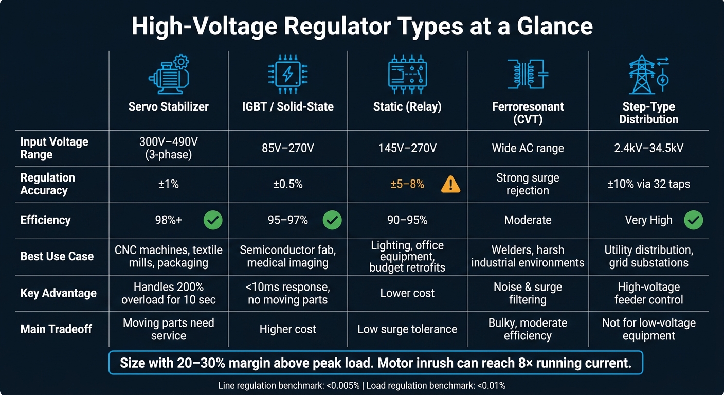
If you’re comparing regulator types, the main split is simple: servo units handle heavy motor loads, IGBT units give tighter control and fast response, static relay units cost less but allow more voltage swing, ferroresonant units help with noisy power, and step-type regulators are for 2,400 V to 34,500 V feeder work.
Quick Comparison
| Type | Best Fit | Main Tradeoff | Typical Numbers |
|---|---|---|---|
| Servo Stabilizer | Heavy industrial motor loads | Moving parts need service | ±1%, 98%+ efficiency |
| IGBT / Solid-State | Fast, tight voltage control | Usually higher cost | ±0.5% precision, 95%–97% efficiency |
| Static (Relay) | Basic correction on lighter loads | Lower surge handling, looser control | ±5% to ±8% |
| Ferroresonant (CVT) | Noisy lines and surge-heavy areas | Bulkier, moderate efficiency | Strong filtering |
| Step-Type Distribution | Utility and substation feeders | Not for low-voltage equipment use | 2.4 kV to 34.5 kV, ±10% via 32 taps |
So if I were reviewing a datasheet, I would not start with brand, price, or form factor. I’d start with the numbers that decide fit, heat, and fault survival.
sbb-itb-501186b
Core Electrical Ratings That Determine Fit
Read regulator datasheets in three layers: absolute maximum, recommended operating, and application target. Those three ratings do not mean the same thing, and the space between them matters more than many buyers think. Once you have that rating order straight, the next step is simple: check whether the source, the load, and the thermal limits line up.
Input Voltage, Output Voltage, and Maximum Output Current
Start with the input range. Match it to the actual source, not the product's power class. Low-power modules often use 24 or 28 Vdc, while higher-power units may use AC mains. And don't stop at the absolute maximum. The recommended operating range is the one that matters day to day. If you run above that range, component life gets shorter.
On the output side, avoid oversizing voltage by more than 20% above the application's actual maximum. For maximum output current, make sure the regulator's continuous current rating meets the load's real demand.
When voltage and current check out, look at the power the regulator burns just to keep that output steady.
Dropout Voltage, Quiescent Current, and Efficiency
Dropout voltage is the minimum gap between input and output voltage that the regulator needs to stay in regulation. Drop below that, and the output falls apart. Quiescent current is the current the regulator pulls from the input just to keep itself alive, even when the load is not the issue.
These two specs hit heat and standby loss directly. Low efficiency turns into heat, and heat means more operating cost. Switching designs usually give you higher efficiency and a smaller footprint than line-frequency units.
Output Accuracy, Line Regulation, and Load Regulation
If the unit works on paper, the next thing to ask is how well it holds the output when conditions move around. Tight line and load regulation matter when the load can't shrug off drift.
Line regulation shows how much the output changes as the input voltage shifts. High-quality high-voltage supplies usually hold better than 0.005% across a ±10% line voltage swing. Load regulation shows output change from no load to full load, with units often performing better than 0.01%.
What counts as "good enough" depends on the job. Semiconductor manufacturing may need ±0.1% regulation, while general motor-drive work can live with ±5%. Also check the stability spec. That's the drift caused by temperature change in the reference voltage, control amplifier offset, and feedback dividers. Stability is usually measured after warm-up, so use that time window if precision matters.
| Spec | What It Measures | Typical High-Quality Value |
|---|---|---|
| Line Regulation | Output change vs. ±10% input swing | Better than 0.005% |
| Load Regulation | Output change from no load to full load | Better than 0.01% |
| Stability | Output drift due to temperature over time | Warm-up drift after stabilization |
Thermal Limits, Protection Features, and Compliance
Power Dissipation, Junction Temperature, and Package Limits
Once voltage and current line up, the next step is simple: can the regulator live with the heat at full load?
Power dissipation goes up as voltage drop and load current go up. If that heat isn’t controlled, junction temperature climbs, and service life can drop with it. That’s why it’s worth checking the derating curve, maximum junction temperature, and enclosure limits against your worst-case ambient conditions.
A regulator that looks fine on paper can still run too hot in practice. Ambient temperature, enclosure size, and duty cycle all shape cooling performance. A unit inside a tight cabinet on a hot summer day is dealing with a very different thermal load than the same unit in open air.
Overcurrent, Short-Circuit, and Overtemperature Protection
Heat is only part of the story. Fault handling matters too.
Check for current limiting, overload shutdown, thermal shutdown, and automatic crossover. Most high-voltage regulators include current limiting set near 110% of rated output current. That gives the unit some margin without letting fault current run away.
Here’s how those protection functions usually work:
- Current limiting keeps output current near a set ceiling
- Overload trip-out shuts the unit down during a sustained fault
- Automatic crossover moves the regulator from voltage control to current control at the set limit
Servo regulators add another layer here. They can handle 200% overload capacity for 10 seconds.
After fault protection, confirm the installation rating and the standard the unit needs to meet.
Industrial Standards and Construction Requirements
This is where the datasheet needs to match the job site, not just the circuit.
Use IEEE/IEC C57.15-2017 for step-voltage regulators up to 34,500V, and make sure the enclosure lines up with the needed IP, NEMA, or UL rating. IP20 fits clean indoor panels. If the area has dust, splashing water, or more moisture in the air, look at IP54 or IP65.
NEMA and UL ratings matter even more in packed industrial enclosures and in outdoor or pad-mounted installs. Those settings can be rough on equipment, so enclosure choice isn’t just a box-checking step.
IEEE C57.15 also covers power factor, resistance, and dielectric tests. If the datasheet doesn’t mention those tests, ask the supplier directly. It’s a small step that can save a lot of back-and-forth later.
"A general guideline for Safety Practices is found in IEEE Standard 510-1983 'Recommended Practices for Safety in High Voltage and High Power Testing.'" - Spellman High Voltage Electronics Corporation
High-Voltage Regulator Comparison Table
High-Voltage Regulator Types: Specs, Efficiency & Best Use Cases
Industrial Regulator Types in Real Applications
Once voltage, current, and thermal limits line up, the next step is comparing topology tradeoffs. That’s where the practical differences start to show up. The table below focuses on the points that matter most when you're narrowing down options.
| Regulator Type | Input Requirement | Regulation Range | Max Current | Efficiency | Dropout Voltage | Installation | Typical Use |
|---|---|---|---|---|---|---|---|
| Servo Stabilizer | 300V–490V (3-phase) | ±1% | High | 98%+ | - | Floor/pad mounted | CNC machines, textile mills, packaging |
| IGBT (Solid-State) | 85V–270V | ±0.5% precision | High | 95–97% | - | Rack/floor mounted | Semiconductor fab, medical imaging |
| Static (Relay) | 145V–270V | ±5–8% | Moderate | 90–95% | - | Wall/floor mounted | Lighting, office equipment, budget retrofits |
| Ferroresonant (CVT) | Wide AC range | Strong line-noise and surge rejection | Moderate | Moderate | - | Cabinet/floor mounted | Welders, harsh industrial environments |
| Step-Type (Distribution) | 2.4kV–34.5kV | ±10% via 32 taps | Very high | Very high | - | Pole or substation | Utility distribution, grid substations |
Use these tradeoffs to narrow the field, then check the exact electrical and thermal ratings in the datasheet.
Noise sensitivity is often the cleanest dividing line between linear and switching types. LDOs run quietly with minimal EMI, so they fit best as the final clean-up stage on 4–20 mA sensor loops and PLC analog cards.
At the industrial level, the servo vs. IGBT choice usually comes down to response time and precision. IGBT units respond in under 10 ms and have no moving parts. Servo designs, on the other hand, need periodic maintenance for brushes and bearings.
Motor loads need extra care here. Go with servo stabilizers instead of static (relay/triac) units when high inrush startup current is part of the job. Static units have lower surge tolerance and can fail under those conditions.
Selection Checklist and Conclusion
Specification Review Before Ordering
After you compare regulator types, run one last check before placing the order. This step helps you avoid the kind of mismatch that looks fine on paper and turns into a headache on site.
Start with the electrical fit. Measure the site voltage range and frequency over 24–48 hours, not just from the nameplate. Then compare that full variance range with the regulator's documented input bandwidth. Next, total your maximum continuous load wattage, account for power factor, and add a 20%–30% margin above peak load. If you're dealing with motor loads, size for starting kVA, not just running demand. Inrush can hit 8× steady-state current.
Once the electrical side checks out, confirm the installation can deal with heat and fault conditions. Keep ambient temperature below 95°F (35°C). If it climbs above 104°F (40°C), service life drops. On three-phase systems, use the √3 factor to verify line voltage.
Protection features should be treated as a must-have, not a nice extra. Check for:
- Overvoltage and undervoltage cutoff
- Overload protection
- Fast short-circuit isolation
- Surge suppression
If the system runs on a 60 Hz grid, make sure the AVR includes Under Frequency Roll Off (UFRO) starting at 57 Hz. That setting helps prevent core saturation during frequency drops.
For compliance documentation, ask for certified test data that covers dielectric strength, temperature rise, short-circuit capability, and impulse tests. Compare the datasheet revision with the third-party test reports, not the marketing sheet. Get those documents before you order.
If you're buying used equipment, check the service history and current condition. And watch this point closely: do not install or remove an energized regulator with the tap changer off neutral. That can short part of the series winding.
For new or used units, Electrical Trader provides a centralized marketplace for high-voltage regulators and related power equipment.
FAQs
How do I size a regulator safely?
Start by calculating total equipment demand in kVA.
For single-phase loads, use:
(Volts × Amps) / 1,000
For three-phase loads, use:
(Volts × Amps × 1.73) / 1,000
That gives you the base load. From there, adjust for equipment that pulls extra current at startup.
For motors or welders, size the regulator 30% to 50% above full load so it can handle starting current. Then add another 10% to 25% as a safety margin if you expect future expansion.
Which regulator type fits my load?
The right regulator comes down to three things: your power source, how sensitive the load is, and how much the input voltage moves around.
For sensitive electronics, Servo or IGBT regulators are usually the better fit, with accuracy up to ±0.5%. For general machinery or lower-cost setups, relay-based regulators are often enough.
If the starting current is high, size the regulator 30% to 50% above the full load. You’ll also want to check whether you need single-phase or three-phase support, especially if the three-phase supply is unbalanced.
What ratings matter most on site?
The ratings that matter most are input voltage range, output voltage accuracy, and capacity.
Start by identifying the input voltage you have and the output voltage your equipment needs. Then calculate the total load in kVA.
Add some headroom:
- Use a 10% to 25% buffer if you expect future growth
- Use 30% to 50% if your setup has high inrush currents
It’s also smart to check efficiency. Aim for above 97% if possible. And look at response time, which tells you how fast the unit reacts to voltage swings.


