How High Voltage Transformers Support Backup Systems
High voltage transformers (HVTs) are critical in ensuring reliable backup power for facilities like hospitals, data centers, and industrial plants. They stabilize voltage, protect equipment, and enable smooth transitions between grid and backup power. Here’s how they work and why they matter:
- Voltage Conversion: HVTs adjust voltage levels (e.g., from 480V to 13.8 kV) to match facility needs.
- Electrical Isolation: They shield sensitive equipment from voltage spikes and faults.
- Bidirectional Power Flow: Modern HVTs manage both charging and discharging in systems with Battery Energy Storage Systems (BESS).
- Applications: Used in hospitals, data centers, and more, they support critical systems during outages.
Proper planning, sizing, and maintenance ensure HVTs provide reliable power when it’s needed most. This guide covers everything from load calculation to redundancy strategies.
Planning and Sizing High Voltage Transformers for Backup Systems
Identifying Critical Loads
Before you can size a transformer, you need a detailed understanding of what it will power. Start by categorizing loads into three groups:
- Critical/emergency loads: These include life safety systems, servers, and ICU equipment.
- Essential loads: Think HVAC systems, elevators, or specific process pumps.
- Non-essential loads: These can be turned off during an outage.
To calculate the Maximum Demand (MD), multiply each load's rated power by its demand factor:
Total Load (kW) = Σ (Rated Power × Demand Factor).
In industrial environments, demand factors typically fall between 0.6 and 0.75, as not all equipment runs simultaneously. Sizing a transformer based solely on the total load may lead to inefficiencies.
"Transformer sizing is a balance between engineering safety and economic sense. Too small → overheating and failures. Too large → unnecessary capital cost and inefficiency." - EngineersDiary
Additionally, account for the highest transient loads. For example, motor startups can draw 5–7 times their normal current, and UPS systems may add recharging demands. Identifying these loads accurately is essential before moving on to capacity calculations.
Voltage and kVA Sizing
Once you’ve categorized your loads, the next step is calculating the required transformer capacity in kVA. For a three-phase system, use the formula:
kVA = (V × I × 1.732) / 1000.
Round your result to the nearest standard kVA size and include a 20–30% margin for future growth.
Next, consider the transformer’s impedance (%Z). For distribution transformers under 1 MVA, impedance typically ranges from 4–6%, while larger transformers (over 10 MVA) fall between 8–12%. Impedance affects both voltage regulation and fault currents. Use the formula I_sc = I_FLA / (%Z / 100) to ensure downstream protective devices can handle the available fault current.
For systems with harmonic-heavy loads - like VFDs, UPS systems, and IT equipment - opt for a K-rated transformer. A K-13 transformer works well for most VFD and UPS setups, while data centers with significant drive loads may need a K-20 unit.
| K-Factor Rating | Typical Load Types |
|---|---|
| K-4 | Office computers, PLC equipment |
| K-13 | VFDs, UPS systems |
| K-20 | Data centers, heavy drive loads |
Beyond these calculations, ensure compliance with local design standards.
U.S.-Specific Sizing Considerations
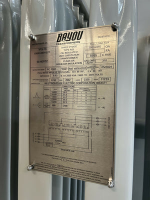
In the United States, primary voltage is typically dictated by the utility interconnection. Common distribution-primary voltage classes include: 4.16 kV, 12.47 kV, 13.2 kV, 13.8 kV, 25 kV, and 34.5 kV. Secondary voltage depends on load requirements. For instance:
- 480Y/277V: Ideal for large motors and lighting, as it reduces current draw and allows smaller conductors.
- 208Y/120V: Common for general receptacle loads.
All transformers in the U.S. must meet IEEE C57.12.00 and NEC Article 450 standards. Additionally, U.S. systems operate at 60 Hz, which is a key difference from regions using 50 Hz. For installations above 3,300 feet, plan to derate the transformer’s kVA rating due to reduced air density affecting cooling.
When budgets are tight, consider cost-effective options like used or reconditioned transformers from sources such as Electrical Trader. Whether you choose new or used equipment, early coordination with your utility is essential. Utilities often specify the metering point (HV vs. MV side), which can affect ownership and maintenance responsibilities.
sbb-itb-501186b
Step-by-Step Guide: Integrating High Voltage Transformers into Backup Systems
How to Integrate High Voltage Transformers into Backup Power Systems
Once you've identified your loads and sized your transformer, the next step is turning your plan into a functioning backup system. Here's how to go from concept to reality.
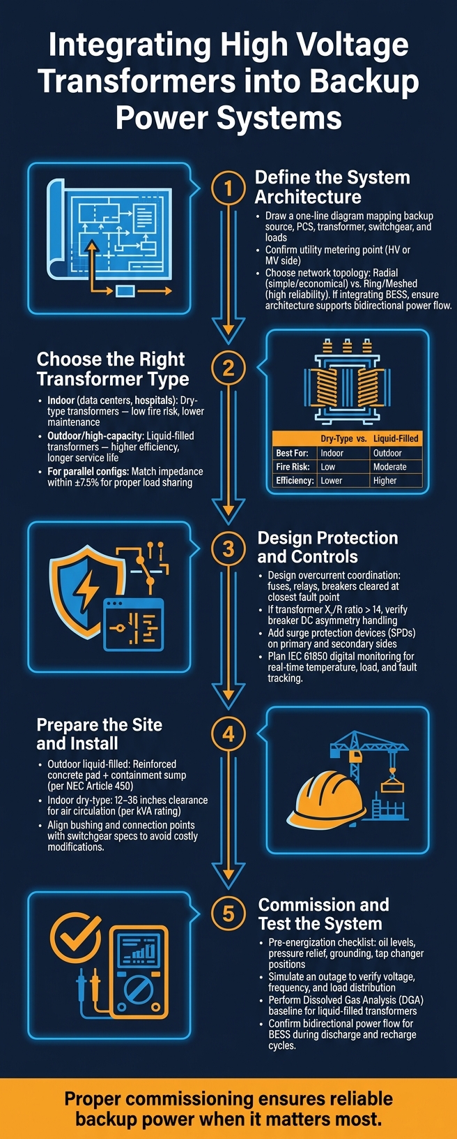
Step 1: Define the System Architecture
Start by creating a one-line diagram that maps out the backup source, PCS, transformer, switchgear, and connected loads. This diagram helps pinpoint any protection gaps or transformer placement issues before purchasing equipment.
Next, confirm the utility metering point (HV or MV), as this will affect equipment ownership, maintenance responsibilities, and tariff rates. Decide on the network topology - a radial layout is simpler and more economical, while an open ring or meshed configuration offers greater reliability for operations that can't afford prolonged downtime. If you're integrating a BESS (Battery Energy Storage System), make sure the architecture supports bidirectional power flow for both charging and discharging.
"In simple terms, the BESS Transformer helps the battery system 'speak the same voltage language' as the site or grid." - BoostESS
With the architecture in place, it's time to select the right transformer.
Step 2: Choose the Right Transformer Type
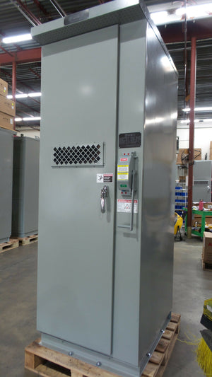
The installation environment plays a big role in transformer selection. For indoor spaces like data centers, hospitals, or backup rooms, dry-type transformers (cast-resin or vacuum-pressure impregnated) are a good fit due to their fire safety advantages. For outdoor or high-capacity setups, liquid-filled transformers are better, offering higher efficiency and longer service life, though they come with added maintenance needs.
In sensitive indoor areas, consider using FR3 natural ester fluid, which has a high fire point of around 300°C (572°F). For parallel configurations - common in redundant systems - ensure the transformers have impedance values within ±7.5% to allow proper load sharing.
| Feature | Dry-Type | Liquid-Filled (Oil/FR3) |
|---|---|---|
| Best For | Indoor, fire-sensitive areas | Outdoor, high-capacity substations |
| Fire Risk | Negligible | Low (FR3) / Higher (Mineral oil) |
| Efficiency | Moderate | Higher |
| Maintenance | Lower (no fluid testing) | Higher (requires fluid sampling) |
Once your transformer type is chosen, focus on protection and control design.
Step 3: Design Protection and Controls
Start by designing overcurrent coordination. Ensure that fuses, relays, and breakers are set to clear faults at the closest point without tripping upstream devices unnecessarily. Use the short-circuit formula to confirm that downstream breakers can handle fault currents.
If your transformer's X_t/R ratio exceeds 14, consult the circuit breaker manufacturer to confirm it can handle the resulting DC asymmetry. For systems connected to inverters or UPS equipment, include surge protection devices (SPDs) on both the primary and secondary sides. Also, plan for digital monitoring systems from the beginning - modern setups using IEC 61850 communication allow real-time tracking of temperature, load, and potential faults.
"The analysis clearly illustrates that specifying the right z_t value in the design phase is key to optimizing the cost and performance of a large site's MV electrical installation." - Schneider Electric White Paper 258
Step 4: Prepare the Site and Install
This step involves setting up the physical infrastructure. Outdoor liquid-filled transformers need a reinforced concrete pad sized to their footprint, plus a containment sump to capture leaks, as required by NEC Article 450 and local fire codes. Indoor dry-type transformers require sufficient clearance for air circulation - usually between 12 and 36 inches, depending on the kVA rating, as specified in the manufacturer's manual.
Plan bushing and connection points carefully to align with switchgear specifications, whether using cover-mounted or sidewall-mounted bushings. Poor alignment can lead to costly modifications during installation.
Step 5: Commission and Test the System
Before energizing the system, go through a pre-energization checklist. For liquid-filled transformers, check oil levels and pressure relief settings. Confirm grounding, neutral connections, and tap changer positions. An incorrectly set No-Load Tap Changer (NLTC) or On-Load Tap Changer (OLTC) can result in secondary voltage issues for backup loads.
Simulate an outage during functional testing to verify that voltage, frequency, and load distribution are within acceptable limits. For liquid-filled transformers, perform a dissolved gas analysis (DGA) to establish a baseline for insulation health monitoring over time. If your system includes battery storage, ensure the transformer handles bidirectional power flow correctly during both discharge and recharge cycles.
Reliability and Redundancy Strategies for Backup Systems
Redundant Transformer Configurations
Once your system is up and running, it's crucial to prepare for potential transformer failures ahead of time.
N+1 redundancy ensures you have one extra transformer beyond the required load. This spare unit is ready to take over if any single transformer goes offline.
"N+1 redundancy means you have one additional transformer beyond what's required to support your full load. If you need three transformers... to power your facility (N=3), you install four transformers (N+1=4)." - Meta Power Solutions
For facilities where even a momentary power loss is unacceptable - like hospitals or other mission-critical operations - 2N redundancy offers a more robust solution. This setup duplicates the entire power path, allowing operations to continue even if two failures occur simultaneously. While this approach demands more physical space and resources, it provides unmatched reliability. A hybrid approach, combining N+1 redundancy for transformers with 2N redundancy for UPS systems, strikes a balance between cost and reliability.
Another effective strategy is loop feed configurations, which connect transformers using two sets of primary bushings (six in total). This setup allows transformers to draw power from two independent sources. If one source fails, the other automatically takes over, ensuring uninterrupted power - ideal for critical facilities.
| Redundancy Type | Configuration | Failure Tolerance | Best For |
|---|---|---|---|
| N+1 | 1 extra unit beyond capacity | Single failure | Enterprise data centers |
| 2N | Full duplication of all power paths | Dual failure | Mission-critical facilities |
| Hybrid | N+1 at transformer + 2N at UPS | High reliability | Cost-conscious high-uptime needs |
These strategies are essential for reducing downtime and ensuring preparedness during emergencies.
Reducing Downtime
Redundancy is just one piece of the puzzle - restoring operations quickly after a failure is equally important. Standardizing transformer specifications, such as kVA ratings, voltage classes, and busbar configurations, simplifies sourcing and replacement during emergencies. Many suppliers can ship matching units within 24 to 48 hours, whereas custom-built transformers may take weeks or months.
For facilities where downtime is costly, keeping an on-site spare transformer can eliminate shipping delays entirely. This upfront investment can save significant time and money in the long run. At the very least, pre-installing conduits, bus infrastructure, and pads can allow for quick drop-in replacements without major modifications.
"A single substation transformer failure can affect thousands of customers, making reliability and protection system design critical considerations." - Hao Liu, Sales Engineer
Additionally, using selective coordination in your protection system can minimize the impact of faults. Properly coordinated relays ensure that only the affected section of the system is isolated, leaving the rest operational while the issue is resolved.
Emergency Response Planning
Even with redundancy and downtime strategies in place, a well-thought-out emergency response plan is essential. The first 15 minutes after a transformer failure are critical.
"The first 15 minutes after a transformer failure set the tone for everything that follows." - Todd Benadum, ELSCO Transformers
Your emergency plan should include detailed specifications for every transformer on-site - covering primary and secondary voltages, kVA ratings, impedance, temperature rise class, and physical dimensions. Having this information ready ensures suppliers can confirm compatibility before shipping, avoiding delays and costly mistakes. Establishing a pre-approved supplier list with 24-hour emergency contacts and confirmed stock of standard transformer models is another key step.
Additionally, arrange rigging and crane services in advance. A replacement transformer on-site is useless if delays occur in lifting it into place. Pre-coordinated logistics can significantly reduce replacement time. Once the new unit is installed, gradually load it and monitor its performance over several hours before resuming full operations.
Maintenance and Lifecycle Management for High Voltage Transformers
Routine Maintenance Practices
Keeping high voltage transformers in top condition requires proactive maintenance. This approach ensures they remain reliable during power outages, catching small issues before they turn into major failures.
"Transformer maintenance is less about 'finding problems' and more about preventing small abnormalities from becoming power transformer failure causes." - Scotech
A structured inspection schedule makes this process manageable:
- Daily: Check oil levels, load currents, and temperature indicator readings.
- Weekly: Inspect silica gel breathers. If the color shifts from blue to pink, it's time to replace the breather to prevent moisture from entering the insulation system.
- Monthly: Examine bushings for any cracks and ensure radiator fins are free from blockages. Dust buildup, for example, can reduce cooling efficiency by over 20% in dry-type transformers.
- Annually: Perform oil sampling to test dielectric breakdown voltage (BDV) and dissolved gas analysis (DGA). Additionally, conduct an infrared thermographic survey to identify hot spots that could lead to damage.
When replacing breathers, temporarily set the Buchholz relay to alarm mode to avoid unnecessary system trips.
These regular checks lay the groundwork for advanced monitoring systems that further improve reliability and performance.
Condition Monitoring
Modern systems increasingly rely on continuous online monitoring instead of periodic manual inspections. This method provides ongoing trend data, offering a clearer picture of transformer health.
Dissolved Gas Analysis (DGA) is a cornerstone of early-warning systems. It detects early signs of arcing, overheating, and insulation issues. When combined with real-time temperature and load sensors, operators can spot thermal stress patterns. For instance, a stable load paired with rising temperatures often signals inefficient cooling rather than an overload problem.
Other tools enhance the monitoring process:
- Online Frequency Response Analysis (OnFRA): Detects mechanical issues like inter-turn short circuits.
- Electrical Signature Analysis (ESA): Identifies loose connections and power quality problems without taking the transformer offline.
"The emerging Substation 4.0 paradigm addresses these limitations by integrating smart sensors, online diagnostic techniques, and data-driven decision-making to enable real-time health assessment and proactive asset management." - Fabio Henrique de Souza Duz et al.
The table below highlights key oil test thresholds to monitor for in-service transformers:
| Test | What It Measures | Service Threshold |
|---|---|---|
| Breakdown Voltage (BDV) | Dielectric strength of oil | Above 40 kV |
| Moisture Content | Water contamination | Below 15 ppm |
| Neutralization Number | Oil oxidation/acidity | Below 0.5 mg KOH/g |
| Dielectric Dissipation Factor | Insulation aging | Below 0.5% at 90°C |
Lifecycle Planning and Replacement
Continuous monitoring supports effective lifecycle planning, ensuring transformers deliver optimal performance for as long as possible. High voltage transformers typically last 25–40 years, with the Degree of Polymerization (DP) of cellulose insulation serving as a critical health metric. New transformers have DP values between 1,000 and 1,400, but when that drops below 200, the insulation loses its mechanical strength, signaling the end of the transformer's reliable service life.
"Replacement planning should be condition-based, not age-based." - PowerNex
Many transformers enter a "grey zone", where the core components remain functional, but parts like bushings, cooling systems, and tap changers require more frequent upkeep. This phase is an ideal time to decide between refurbishment and full replacement. For units above 100 MVA, lead times of 12–24 months make early planning essential to maintaining backup continuity.
For facilities balancing cost and reliability, sourcing refurbished or used transformers can be a practical solution. Platforms like Electrical Trader offer a wide variety of options, making it easier to find compatible replacements quickly, especially when commissioning records provide clear specifications.
Conclusion
This guide outlines a step-by-step approach to ensure the reliability of backup power systems, emphasizing how every decision - from sizing to installation - affects long-term performance. High voltage transformers play a crucial role in maintaining dependable backup power. For instance, transformers are often specified at 125–150% of the UPS rated capacity to manage inrush currents effectively, which is a key factor in ensuring system stability over decades of use.
The principles discussed throughout this guide work together to create a cohesive strategy. Choosing the right redundancy configuration, such as N+1 for enterprise facilities or 2N for mission-critical operations, ensures that no single failure leads to a complete outage. Proper installation practices, like maintaining impedance matching within ±7.5% for parallel units and using K-rated transformers for harmonic-heavy loads, further enhance system stability during real-world operations.
"The transformer specification you choose directly impacts your facility's reliability, operational efficiency, and ability to scale." - Meta Power Solutions
Ongoing maintenance and monitoring are equally important. Techniques like annual thermographic surveys, oil quality testing, and tools such as dissolved gas analysis (DGA) enable operators to detect and address potential issues before they escalate, ensuring uninterrupted operations. When a transformer reaches the end of its service life, replacing it based on condition rather than age helps maintain a seamless power supply.
In critical situations, the precise specifications and strategies outlined here ensure backup systems respond without fail, protecting essential operations. Features like efficient designs, eco-friendly insulating fluids, and advanced digital monitoring tools further enhance the reliability of backup infrastructure. By treating transformers as strategic assets, facilities not only meet immediate power demands but also lay the groundwork for future scalability and resilience.
FAQs
How do I size an HVT for my backup loads?
To correctly size a high voltage transformer (HVT) for backup loads, start by calculating the total load in kilovolt-amperes (kVA). If you're working with a three-phase system, you can use this formula:
kVA = (V × I × 1.732) / 1,000
Here’s a breakdown of the process:
- Account for Diversity Factors: Adjust for non-simultaneous usage of equipment to avoid oversizing unnecessarily.
- Include a Safety Margin: Add a 20–25% buffer to accommodate future growth or unexpected load increases.
- Using Kilowatts Instead?: If your load is measured in kilowatts (kW), divide it by the power factor (commonly 0.85) to convert to kVA.
Finally, select the next standard NEMA size to ensure reliable operation and accommodate potential fluctuations in demand.
Do I need a K-rated transformer for UPS or VFD loads?
K-rated transformers are commonly needed for loads like UPS systems or VFDs because these devices produce non-sinusoidal currents. This can lead to harmonic heating, which standard transformers aren’t designed to handle. While K-rated transformers are built to manage this excess heat, it’s important to note that they don’t reduce harmonics or offer electrical isolation. For sensitive environments, such as data centers, a transformer with a K-20 rating or higher is usually recommended. Electrical Trader provides a range of transformers to help meet your power requirements.
What redundancy setup (N+1 vs 2N) fits my facility?
When choosing a redundancy setup, it all comes down to your facility's uptime requirements and how much risk you're willing to accept.
- N+1: This setup includes one extra unit as a backup, offering a decent level of reliability. It ensures operations can keep running if a single component fails. However, during maintenance, redundancy is temporarily unavailable.
- 2N: This approach goes all-in by duplicating power paths entirely. It's the go-to choice for facilities where downtime isn't an option, like hospitals. That said, it demands more space and a higher financial commitment.
Electrical Trader provides the components you need to implement either of these redundancy setups effectively.