




Ultimate Guide to Dielectric Strength Testing
If you test insulation the wrong way, a “pass” can still mislead you. I’d boil this topic down to four points: use the right standard, know whether you’re testing a material or finished equipment, apply the right voltage for the right time, and treat high-voltage safety like part of the test - not an extra step.
Here’s the short version in plain English:
- Dielectric strength tells me how much electric field an insulating material can take before it fails.
- Breakdown voltage is the voltage where a sample actually fails during a lab test.
- Hipot or dielectric withstand is a pass/fail check on finished equipment, often at a set voltage for 60 seconds.
- A common rule of thumb is 2 × rated voltage + 1,000 V, but I would not use that without checking the product standard first.
- ASTM D149 and IEC 60243 are used for material tests.
- UL, NETA ATS, and IEC 60076-3 are used for finished gear such as panels, switchgear, and transformers.
- AC hipot is often used when service stress is AC.
- DC hipot fits some cable and field uses, but it is not always the right pick for modern polymeric cable insulation.
- Insulation resistance testing is useful for trend data, but it does not prove high-voltage withstand.
- Leakage current matters: a steady low reading is one thing, but a rising or spiking reading can point to moisture, dirt, aging, tracking, or internal failure.
The big takeaway: I’d never read dielectric test results as just “pass” or “fail.” The test method, leakage pattern, dwell time, and safety controls all matter just as much.
A quick side-by-side view:
| Test | What I use it for | What it tells me | Common result |
|---|---|---|---|
| Dielectric strength | Material evaluation | How much field a material can take before breakdown | kV/mm or V/mil |
| Breakdown test | Lab failure testing | The voltage where the sample fails | Failure point |
| AC/DC hipot | Finished equipment check | Whether insulation holds a set voltage | Pass/fail |
| Insulation resistance | Maintenance trending | General insulation condition at low DC voltage | Resistance value |
If I were skimming this guide for the answer fast, it would be this: match the test to the asset, follow the governing standard, watch leakage current during the hold period, and fully discharge before anyone touches the equipment.
Dielectric Withstand Test
sbb-itb-501186b
Standards, Ratings, and Test Requirements
Now that the difference between material testing and equipment testing is clear, the next job is simple in theory but easy to get wrong in practice: match the right standard to the asset. That choice sets the test voltage, the test time, and what counts as a pass.
Key Standards for Materials, Panels, Switchgear, and Transformers
The first split is this: are you testing a material sample or a finished piece of equipment?
ASTM D149 is the main U.S. standard for measuring dielectric breakdown voltage and dielectric strength of solid insulating materials at commercial power frequencies, usually 60 Hz. It lays out the test methods, voltage application modes, electrode setups, specimen thickness, and surrounding media like air or oil. If the goal is comparative AC breakdown testing for solid insulation, ASTM D149 is the standard to use.
On the IEC side, IEC 60243-1 covers short-time electric strength testing of solid insulating materials at power frequencies from 48 Hz to 62 Hz. IEC 60243-2 applies the same general idea to DC voltage testing. For power transformers, IEC 60076-3 covers dielectric tests such as applied voltage, induced voltage, lightning impulse, and switching impulse tests. For low-voltage panels and switchgear, UL product standards and NETA ATS define factory and field dielectric withstand test rules.
| Standard | Applies To | Primary Test Type |
|---|---|---|
| ASTM D149 | Solid insulating materials | Dielectric breakdown / strength (AC) |
| IEC 60243-1 | Solid insulating materials | Short-time electric strength (AC, 48–62 Hz) |
| IEC 60243-2 | Solid insulating materials | Dielectric strength (DC) |
| IEC 60076-3 | Power transformers | Applied voltage, induced voltage, impulse tests |
| UL product standards | Panels, switchgear, equipment | Dielectric voltage withstand |
| NETA ATS | Installed equipment | Acceptance dielectric withstand tests |
Test Voltage Rules and Time Durations
Once you know which standard governs the test, the next issue is how much voltage to apply and for how long.
A common U.S. shortcut is 2 × rated voltage + 1,000 V. You’ll see that formula in many product safety standards and compliance guides, but it is not a blanket rule. The multiplier and the added voltage change by standard, product class, and insulation category. So it’s a handy reference point, not something to apply on autopilot. Check the exact requirement in the standard that applies to the asset in front of you.
For dwell time, one minute is the most common rule across many equipment types. UL defines the dielectric voltage withstand test as applying a specified test voltage across the insulation barrier for one minute. NETA ATS calls for one-minute tests on each bus section and phase-to-ground. Low-voltage switchgear procedures usually require the voltage to ramp up to the target level within 5 to 10 seconds and then stay there for 60 seconds.
Material tests work a bit differently. ASTM D149 includes three voltage application methods:
- Short-time: a continuous ramp to breakdown
- Step-by-step: voltage increases in steps with hold periods
- Slow rate-of-rise: lower ramp rates to limit thermal effects
IEC 60243-1 gets more specific. It defines rapid-rise, 20-second step-by-step, 60-second step-by-step, 120- to 240-second slow rate-of-rise, and 300- to 600-second very slow rate-of-rise methods.
Once the standard sets the voltage and time, the quality of the procedure matters just as much. The next part is choosing the tester, setting up the test correctly, and putting the right safety controls in place.
Test Equipment, Setup, and Safe Procedures
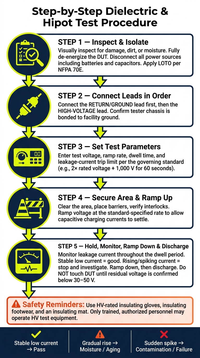
Dielectric & Hipot Testing: Step-by-Step Safe Procedure
Testers, Fixtures, and Measurement Points
Once the standard defines voltage and time, the next job is getting the setup right and keeping people safe.
Pick the tester based on the asset and the goal of the test. AC hipot testers apply alternating voltage and put insulation under stress that looks more like normal service conditions. DC hipot testers apply direct voltage and are often used for certain cable and component tests. Dielectric breakdown testers are used in material evaluation to find the voltage where a specimen fails. Many current testers combine AC/DC hipot, insulation resistance, ground bond, leakage current measurement, ramp control, discharge, and data logging in one unit. For material and oil testing under ASTM D149 or IEC 60243, the setup also uses standardized electrode assemblies and oil test cells so geometry and the surrounding medium stay tightly controlled.
Where you place the measurement points changes what the test is actually measuring. Voltage is applied between the high-voltage lead and the return point. The ground return connects to the DUT chassis, shield, or fixture ground, depending on the setup. For multi-conductor cables or multi-pin connectors, connect all energized conductors together to the HV lead and bond all accessible metal parts and shields to the return lead. In precise lab work, a guard connection can divert surface leakage away from the measurement path. That helps separate bulk insulation behavior from leakage caused by surface contamination. Keep leads short and connections tight to reduce stray capacitance and false leakage readings.
Step-by-Step Procedure for Dielectric and Hipot Tests
The same basic sequence applies in the field, in the shop, and in the lab. The tools and level of control may change, but the core flow does not.
1. Inspect and isolate
Start with a visual check of the specimen or device. Look for damage, dirt, moisture, and loose hardware. If the unit is plainly defective, don't test it. Fully de-energize the DUT and disconnect it from every power source, including batteries and capacitors.
2. Connect leads in order
Connect the return or ground lead first. Then connect the high-voltage lead. That order lowers risk if the output is live during setup. Before moving on, confirm that the tester chassis is bonded to facility ground.
3. Set test parameters
Enter the test voltage, ramp rate, dwell time, leakage-current trip limit, and any data logging fields before turning on the high-voltage output. Use the applicable standard to set each value.
4. Secure the area and ramp up
Make sure the area is clear, barriers are in place, and interlocks are working. Use the ramp rate called for by the standard so capacitive charging currents have time to settle. That also helps prevent nuisance trips.
5. Hold, monitor, ramp down, then discharge
During the dwell period, watch leakage current the whole time. Stable, low leakage points to sound insulation. Rising current, sudden spikes, flashover, smoke, or audible discharge mean something is wrong. Ramp down in a controlled way, then discharge with the tester or with a grounding stick for high-capacitance DUTs. Do not touch the DUT until residual voltage is confirmed below 30–50 V.
These three test types mainly differ in how they stress insulation and what they track:
| Test Type | Typical Voltage Basis | Duration | Monitored Output |
|---|---|---|---|
| AC hipot (withstand) | 2× working voltage + 1,000 V | Per standard | Leakage current, pass/fail |
| DC hipot (withstand) | Per standard or cable rating | Per standard | Leakage current, step stability |
| Dielectric breakdown | Ramp to failure | Short-time, step, or slow rate-of-rise | Breakdown voltage |
Electrical Safety Controls for High-Voltage Testing
High-voltage testing brings real danger, so the safety controls are not optional. At a minimum, use physical barriers or interlocked enclosures that shut off the HV output if a door or panel opens. Post clear warning signs before testing starts. Put an emergency stop where the operator can reach it right away, without stepping away from the station.
LOTO applies to the device under test, not only to the tester. Before any leads are connected, the DUT must be locked out from its normal power source under NFPA 70E procedures. PPE for high-voltage testing includes insulating gloves rated for the test voltage, insulating footwear, and an insulating mat at the operator's position. Only trained, authorized personnel should run high-voltage test equipment, and access to the area should stay limited to those people during the test.
A lot of the danger comes from stored charge. Discharge first, then verify before touching anything. DC tests on long cables are especially risky because the cable behaves like a large capacitor. Check that residual voltage is below 30–50 V before making contact.
With the setup in place, the next step is reading leakage current, trip behavior, and failure mode the right way.
How to Read Results and Compare Test Methods
Once the test is done, the hard part starts: reading the trace the right way and picking the right test method for the asset in front of you.
Pass, Fail, Leakage Current, and Common Failure Modes
A hipot test passes only when the insulation holds the required voltage for the full dwell time, leakage current stays within the allowed limit, and there is no flashover or puncture.
Don’t look only at the final number. Watch the leakage-current curve. A sharp spike often points to contamination or damage. A slow upward climb usually points to moisture, temperature effects, or aging.
| Failure Mode | Likely Cause | Test Signature | Follow-Up Action |
|---|---|---|---|
| Flashover | Surface contamination, tracking, or insufficient creepage | Sudden current spike; arc along the surface; tester trips | Clean, dry, and retest; review creepage and clearance if it repeats. |
| Puncture | Internal dielectric failure or mechanical damage | High sustained current; permanent damage; tester trips | Remove from service and inspect for tracking or a physical breach. |
| Unstable leakage | Partial discharge, contamination, or incipient breakdown | Rising, oscillating, or intermittent current surges during dwell | Run insulation resistance or partial-discharge testing before re-energizing. |
| Moisture ingress | Water, condensation, or degraded seals | Elevated leakage and a gradual rise during the test | Dry the equipment, inspect seals and breathers, then retest. |
| Severe aging | Thermal or mechanical degradation | Elevated leakage, failure near operating voltage, visible cracking | Use the result to support repair or replacement. |
AC vs. DC Hipot and Dielectric Strength vs. Insulation Resistance
The same high-voltage test does not always tell you the same thing. It depends on the equipment, the type of stress it sees in service, and whether you’re doing a formal withstand check or routine condition monitoring. That’s why method choice matters.
AC hipot applies a 60 Hz sinusoidal voltage, which closely matches normal service conditions for power equipment. Because of that, it’s the standard option for switchgear, transformers, motors, and control panels. It also does a good job of showing surface tracking and partial discharge.
DC hipot uses a steady direct voltage. The gear is usually smaller and easier to carry, so it works well for field testing and older PILC cables. But modern polymeric cables like XLPE and EPR are a different story. DC can build space charge in that insulation, so VLF AC is usually the better fit.
Insulation resistance testing answers a different question. It measures how much resistance the insulation gives under a low DC test voltage, but it does not prove the insulation can survive a high-voltage event. That distinction matters. A good insulation resistance result does not guarantee withstand performance, and a hipot pass does not replace insulation resistance trending.
A simple way to think about it: insulation resistance tells you how the insulation is behaving over time, while hipot tells you whether it can take a set voltage stress right now. Use insulation resistance for routine monitoring and trending. Use hipot for formal withstand checks at commissioning, after repairs, or when the applicable standard calls for it.
| Method | Voltage Type | Best Use Case | Strengths | Limitations |
|---|---|---|---|---|
| AC hipot | 60 Hz AC | Switchgear, transformers, motors, panels, and other AC-stressed assemblies | Closest to service stress; reveals surface tracking and partial discharge | Large equipment for medium/high voltage; capacitive current can complicate interpretation |
| DC hipot | Steady DC | Older PILC cables, DC-stressed circuits, and field testing where portability matters | Portable; useful for leakage-current diagnostics | Not representative of AC service stress; can create space charge in modern polymeric insulation |
| Insulation resistance | Low DC voltage | Routine trending, condition assessment, and post-repair checks | Non-destructive and useful for tracking moisture, aging, and contamination over time | Does not prove high-voltage withstand capability |
Using Test Data for Maintenance, Repair, and Buying Decisions
The best test record is not a one-off pass or fail. It’s a trend.
Track leakage current, applied voltage, dwell time, and any events across test cycles. If leakage current keeps creeping up over time, that can mean more than a single borderline reading that still lands within limits. Teams should record applied voltage, dwell time, peak leakage current, and any visible or reported events for every test cycle, then keep a trend file for each critical asset.
In repair work, repeated failures with the same pattern usually point to a root cause that hasn’t been fixed - things like tracking paths, internal voids, or contamination - instead of one random bad part.
Those records also help when it’s time to buy equipment. For incoming gear, ask for the test voltage, test duration, leakage limit, and the standard used - not just a pass/fail result. On Electrical Trader, check the nameplate, insulation class, and test records before buying used breakers, transformers, or switchgear.
Conclusion: Core Practices for Reliable Dielectric Strength Testing
The big point is simple: follow the standard that governs the asset. That standard tells you the test voltage, test time, and leakage limits.
Use AC or DC hipot based on the kind of stress the asset sees in service. Use insulation resistance to track condition over time, not to prove withstand performance.
If you want repeatable results, the basics matter more than people think. Keep fixtures clean, use fixed measurement points, make sure connections are tight, and record temperature, humidity, and contamination.
Safety also has to stay front and center. Use qualified personnel, put barriers or interlocks in place, and include a controlled discharge step after every DC test.
And pass/fail is only part of the story. Trend data is what helps teams schedule maintenance more wisely and make better repair calls. When buying used breakers, transformers, or switchgear through Electrical Trader, ask for the method, applied voltage, dwell time, and leakage reading. A documented test history is worth far more than a pass/fail stamp.
FAQs
How do I choose between AC hipot and DC hipot?
Choose the test type based on the equipment and what you need to check.
AC hipot uses sinusoidal voltage, usually 60 Hz in the U.S. Because it lines up more closely with normal operating conditions, it’s often the better fit for transformers, switchgear, and AC motors. Another plus: it does not require post-test discharge.
DC hipot uses constant voltage. It works better for high-capacitance equipment such as long cables or motor windings. That said, it does require discharge after testing and is generally avoided for XLPE cables.
What does rising leakage current usually mean?
In dielectric strength testing, a rise in leakage current is a clear warning sign that the insulation may be losing stability or starting to fail.
A slow, steady increase often points to moisture getting into the insulation or to general wear over time.
A sharp jump is more serious. It usually means the insulation has broken down right away or that there’s a local fault in one area.
If leakage current rises without warning or starts fluctuating, stop the test at once for safety.
When should I use insulation resistance instead of hipot?
Use insulation resistance testing for non-destructive, routine checks that help spot moisture, contamination, and aging. It also gives you a baseline for future maintenance, and it should be done before any hipot test.
Use hipot testing to check dielectric strength at higher voltage, but only after insulation resistance meets the minimum required values. That matters because hipot testing can damage equipment if the insulation is already weak.





