Checklist for High Voltage Cable Testing On-Site
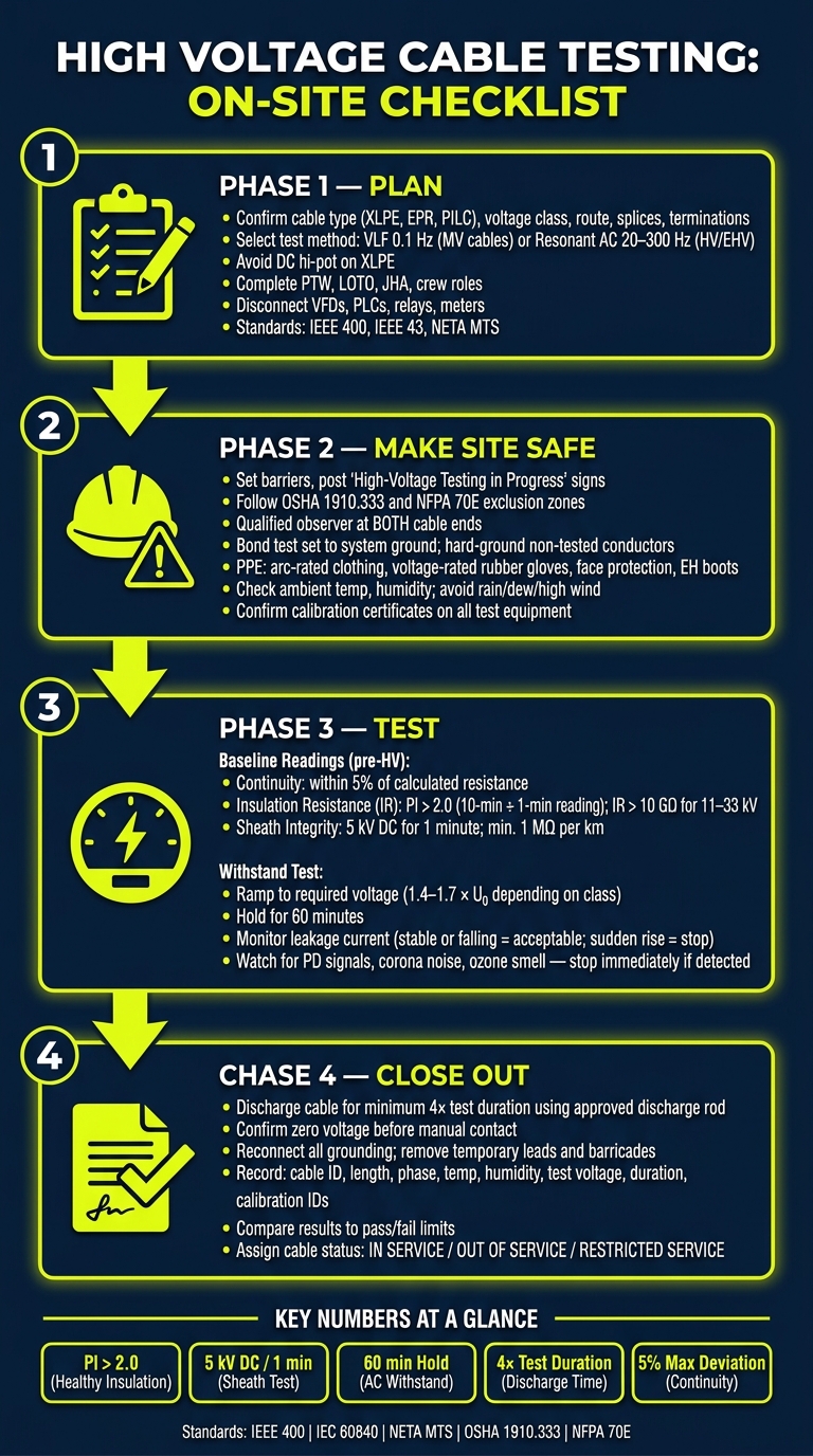
High-voltage cable testing can damage a cable if the job is rushed or the wrong method is used. My takeaway is simple: plan the test, lock out the circuit, verify isolation, run the right AC test, discharge the cable, and document every result before release.
If I had to boil this article down, it says you should:
- confirm the cable type, voltage class, route, splices, terminations, and bonding setup
- choose the right field test method, such as VLF at 0.1 Hz for many MV XLPE/EPR cables or resonant AC at 20–300 Hz for HV/EHV circuits
- avoid DC hi-pot on XLPE
- complete PTW, LOTO, JHA, crew role assignment, and site boundary controls
- disconnect connected electronics like VFDs, PLCs, relays, and meters
- check grounding, PPE, calibration records, and weather before energizing
- take baseline readings for continuity, insulation resistance, PI, and sheath integrity
- hold the test voltage for the stated time, watch leakage current, and stop if you see PD, corona, ozone, or a sudden current rise
- discharge the cable for at least 4× the test duration, then re-ground and restore the circuit
- compare results to pass/fail limits and mark the cable In Service, Out of Service, or Restricted Service
A few numbers stand out right away: PI > 2.0, sheath test at 5 kV DC for 1 minute, continuity within 5% of calculated resistance, and AC withstand hold time often at 60 minutes. The article also points out that early faults often start at accessories and terminations, so those spots need extra attention.
Here’s the short version of the testing flow:
- Plan - scope, standards, permits, roles, and method
- Make the site safe - barriers, grounding, PPE, observer at both ends, radios
- Check and test - isolation, baseline readings, withstand/PD monitoring
- Close out - discharge, re-ground, clean up, report, and release status
This gives you a plain checklist for on-site testing without walking past the safety and documentation steps that often cause trouble later.
High Voltage Cable Testing: On-Site Step-by-Step Process
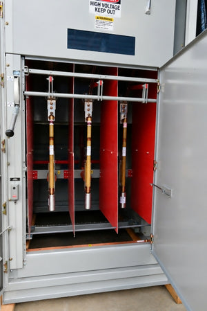
VLF testing of MV cable
sbb-itb-501186b
Pre-Test Planning and Approvals
Before the crew heads out, confirm the cable data, permits, and crew assignments. Once the scope is set, tie the job to the exact cable route and grounding scheme.
Confirm Cable Scope, Standards, and Test Method
Start by checking the cable’s insulation type - XLPE, EPR, or PILC - along with conductor size and total route length. Then confirm the rated system voltage and grounding arrangement, whether solidly grounded or impedance grounded, since that drives test voltage selection. Review the route in detail and identify each termination, splice, and link box setup, including whether it is direct-bonded or cross-bonded.
Before mobilization, choose the governing standard, test method, and voltage class. IEEE 400 is a main reference for field testing, IEEE 43 covers insulation resistance, and NETA MTS applies to maintenance testing.
The table below maps voltage class to test method and the usual test voltage range:
| Cable Voltage Class | Common Test Method | Typical Test Voltage Range |
|---|---|---|
| Medium Voltage (1–33 kV) | VLF Withstand (0.1 Hz) | 3 × U₀ |
| High Voltage (36/66 kV) | Resonant AC (20–300 Hz) | 2.0 × U₀ |
| High Voltage (132 kV) | Resonant AC (20–300 Hz) | 1.7 × U₀ |
| Extra High Voltage (≥ 220 kV) | Resonant AC (20–300 Hz) | 1.18 × U₀ to 1.4 × U₀ |
| All Classes (Sheath) | DC Sheath Test | 5 kV DC |
U₀ = rated power-frequency voltage between conductor and earth.
Before you lock in the test plan, identify every piece of sensitive electronic equipment tied to the circuit. That includes VFDs, PLCs, protective relays, and meters. These items must be disconnected before any test voltage is applied.
Verify Permits, LOTO, and Crew Roles
A Permit to Work (PTW) must be issued for the exact bay or equipment under test so the circuit is confirmed de-energized and access by unauthorized people is blocked. Confirm all needed permits and LOTO boundaries before the test crew arrives on site. Complete a job-specific job briefing, a JHA, and an attendance and sign-off log signed by all personnel.
Set named roles and responsibilities before work begins.
With permits, LOTO, and crew roles signed off, the next step is site setup, grounding, PPE, and equipment checks.
Site Safety and Equipment Readiness
Set Up the Test Area and Grounding Controls
Once permits and LOTO are in place, set the test boundary before any voltage goes on the cable. Put temporary barriers around all cable ends and access points, and post "High-Voltage Testing in Progress" signs at every entry. Exclusion zones and approach boundaries need to match OSHA 1910.333 and NFPA 70E rules. You also need a qualified observer at each end of the cable. Supervision at both ends is required.
Next, bond the test set to system ground. Hard-ground all non-tested conductors, switches, busbars, and instrument transformers. Check that shield grounds are bonded to earth at both terminations. And before you energize anything, stage discharge rods and grounding sticks so they're ready to use at once.
Check PPE, Site Conditions, and Emergency Readiness
At the operator position, minimum PPE includes arc-rated clothing, voltage-rated rubber gloves, eye and face protection, a hard hat, and EH-rated boots. Place insulating rubber mats at the operator position as well. Keep at least two qualified people on-site so one person can run the set while the other monitors the far end.
Before energizing, log the ambient temperature and humidity. That step matters more than it may seem. High humidity can increase surface conductivity and affect dielectric strength readings. Rain, dew, and high winds can also skew test readings and diagnostic signals, so avoid testing in those conditions. For underground work, inspect underground spaces for water, flooding, sediment, and legacy hazardous materials.
Emergency prep can't be treated like an afterthought. First-aid kits, fire extinguishers, and a clearly shared emergency shutdown procedure must all be confirmed on-site and easy to reach before the first test voltage is applied. Keep radio contact between both ends for the full test window.
Confirm Test Equipment, Instruments, and Support Gear
Every piece of test equipment must have a current calibration certificate. Check that the HV test set rating is above the required test voltage for the cable class. For XLPE and EPR cables, VLF sets running at 0.1 Hz are the preferred option because they help avoid space-charge damage. If you're running partial discharge diagnostics, HFCT sensors should be tuned for signal-to-noise ratio at link boxes.
Required Test Gear
| Equipment | Function | Pass/Fail Note |
|---|---|---|
| VLF Test Set | AC withstand testing at 0.1 Hz | Rated for cable voltage class; preferred for XLPE/EPR |
| Resonant AC Test Set | AC withstand testing at 20–300 Hz | Required for HV and EHV cable classes |
| IR Tester | Insulation resistance measurement | Calibrated; voltage selected by cable rating |
| Continuity Meter | Conductor integrity verification | Confirms no open circuits or high-resistance joints |
| Discharge Rod | Residual charge dissipation | Rated for test voltage |
Diagnostic Add-Ons
| Equipment | Function | Pass/Fail Note |
|---|---|---|
| HFCT Sensors | Partial discharge detection | Optimized for signal-to-noise ratio at link boxes |
| TDR / Fault Locator | Pinpointing insulation defects | Used for sheath or core fault location |
With the site locked down and the gear checked, the next step is isolation checks and baseline readings.
On-Site High Voltage Cable Test Execution Steps
Perform Isolation Checks and Baseline Measurements
Once the site is secured, confirm isolation and log baseline readings before any voltage is applied. Start with a pre-energization check. Look at terminations and joints for physical damage or signs of moisture ingress. Also disconnect surge arresters from the cable terminations.
Next, verify absence of voltage at both ends with an approved tester. Then inspect armor wire bonding and grounding connections at both ends, and make sure the grounding system is complete and undamaged.
After isolation is confirmed, take the baseline measurements in this order:
- Continuity - Short and ground all conductors at the far end, then measure resistance at the near end. The measured resistance should be within 5% of the calculated resistance.
- Insulation Resistance (IR) - Test phase-to-phase and phase-to-ground for 1–10 minutes or until the reading stabilizes. Then calculate the Polarization Index (PI = 10-minute reading ÷ 1-minute reading). A PI above 2.0 points to healthy insulation.
- Sheath Integrity - Apply 5 kV DC between the metallic screen or armor and ground for 1 minute. The minimum acceptable result is 1 MΩ per kilometer of cable length.
Record ambient temperature and humidity with every reading. That small step matters, because test values can shift with site conditions.
| Test Type | Sequence Position | Typical Duration | Pass/Fail Indicators |
|---|---|---|---|
| Continuity | Pre-HV Baseline | N/A | Resistance within 5% of calculated value |
| Insulation Resistance (IR) | Pre-HV Baseline | 1–10 minutes | PI > 2.0; IR > 10 GΩ for 11–33 kV class |
| Sheath Integrity | Pre-HV Baseline | 1 minute | Min. 1 MΩ per km of cable length |
| AC/VLF Withstand | Main Execution | 15–60 minutes | No flashover; stable or falling leakage current |
| Partial Discharge (PD) | Diagnostic (Concurrent) | Duration of AC test | No PD signals above background noise |
Run the Withstand or Diagnostic Test and Monitor Conditions
If the baseline readings pass, connect the test set, ground all non-tested phases, and ramp up to the required voltage.
Keep the voltage at the required level for the full stated duration. For AC withstand, the standard hold time is 60 minutes. Commissioning test voltages usually fall between 1.4 × U₀ and 1.7 × U₀, depending on voltage class. During that hold period, watch leakage current the whole time. A stable or falling leakage current is acceptable. A sudden rise is a warning sign and needs attention right away.
Use PD as a diagnostic check only. If you see any signal above background noise, treat it as a defect.
During the hold, pay close attention to the test area. Listen for audible corona noise. Watch for the smell of ozone or burning. Review PD data for treeing-like signatures. If any of those show up, start a controlled shutdown at once.
Discharge, Reground, and Restore Normal Configuration
When the hold time ends, bring the set back to zero. Then discharge and re-ground the cable before anyone handles it.
Use an approved discharge rod to bleed off the stored capacitive charge from the conductor. Discharge the cable for at least 4× the test duration before any handling.
After that, connect a clamp meter to the rod while touching the cable points to confirm a zero-voltage reading before manual contact. Once zero voltage is confirmed, reconnect all metallic screen and armor grounding connections that were lifted for the test. Then restore all permanent grounding systems and verify that they are undamaged.
Finish this phase with site cleanup. Remove all temporary test leads and barricading tape. Check that the area is clear of tools, loose materials, and debris.
Post-Test Documentation and Cable Release
After the cable has been discharged and the area is safe, finish the test report before you close out the job.
Record Results and Compare to Acceptance Criteria
Log the full set of site data so there’s a clear record of what was tested and under what conditions.
Record:
- cable ID
- type
- length
- phase sequence
- ambient temperature
- humidity
- weather conditions
- test settings
- test voltage
- duration
- frequency range
- measured results
- calibration IDs
- phase-to-phase insulation resistance values
- phase-to-ground insulation resistance values
Then compare each result against the right limit. Don’t leave this as a vague review. Match every reading to a clear pass/fail action using the table below.
| Recorded Parameter | Reference Standard | Acceptance Threshold | Action if Failed |
|---|---|---|---|
| AC Voltage Withstand | IEC 60840 / 62067 | No breakdown for 60 mins at 1.4–1.7 × U0 | Locate fault; repair or replace accessory; retest |
| Partial Discharge (PD) | IEC 60840 / 62067 | Absence of internal PD signals after filtering external noise | Inspect joints and terminations |
| Insulation Resistance (IR) | NETA Table 100.1 | >5,000 MΩ for 15 kV class | Check humidity and temperature; investigate moisture or damage |
| Conductor/Screen Resistance | Project Spec / IEC | <10% deviation from expected value | Inspect connectors and joint assembly for high resistance |
| Tan Delta (Power Factor) | CIGRÉ TB 358 | Stable trend; low dielectric loss | Increase inspection frequency; begin life extension planning |
| Contact Resistance (Link Box) | Utility Specification | ≤10 µΩ | Clean contacts, re-torque, or replace link box components |
| SVL Leakage Current | Manufacturer Spec | <0.10 mA at test DC voltage | Replace faulty Sheath Voltage Limiter |
Document Defects, Sign Off, and Set Cable Status
If a result fails, write it up with enough detail to support the repair call. Be specific: note the phase, joint, or termination involved, the measured value, and any immediate control that was put in place. That way, the next crew isn’t left guessing.
The completion register also needs the right signatures. This includes the testing engineer, the site engineer, and any required safety and management signatories.
Before the report is closed, assign one clear cable status: In Service, Out of Service, or Restricted Service.
A cable that passes all criteria can go back into service. A cable that breaks down stays out of service until repair is done. If PD is found but there is no breakdown, use Restricted Service so the cable can stay available while follow-up diagnostics are scheduled.
Final Checklist Before Returning the Cable to Service
Before release, confirm the report includes the cable ID, length, phase sequence, ambient conditions, test voltages, test duration, frequency range, and calibration IDs. Check that each result has been compared directly against the right pass/fail limit.
Also verify that all temporary grounding or shorting leads have been removed. Clear the work area of tools and barricades, and complete any required restoration checks before the cable is returned to service.
FAQs
Which test method fits my cable?
The right test method comes down to three things: your cable’s insulation type, its age, and its voltage class.
For modern XLPE or EPR cables, VLF withstand testing at 0.1 Hz is usually the go-to choice. DC withstand testing may still fit laminated dielectric cables or extruded cables that are less than five years old, but it’s generally a poor match for older XLPE systems.
For high-voltage systems, resonant AC testing in the 20 to 300 Hz range also works well.
Before you set test levels or procedures, check current standards like IEEE 400 or NETA MTS, and match them against your cable manufacturer’s documentation.
Why is DC hi-pot avoided on XLPE?
DC high-potential testing is usually avoided on XLPE cables because it can damage the insulation over time.
Here’s the core issue: DC voltage can cause space charge to build up inside the insulation. That buildup may stress the material in ways that don’t show up right away, but can still lead to insulation breakdown and long-term reliability problems later on.
That’s why industry standards and manufacturer guidelines generally do not allow DC hi-pot testing on XLPE cables. In most cases, VLF withstand testing is the preferred option instead.
What should make a test stop immediately?
Stop a high-voltage cable test at once if you see electrical breakdown, flashover, smoke, or any other physical damage.
During DC high-potential testing, stop the test if leakage current starts to rise or fluctuate. That usually points to failure or instability. If there’s any visible damage, or any sign the insulation integrity is compromised, halt the test right away for safety.