




Ultimate Guide to Scalable Power Distribution
If you expect your facility load to grow, design the power system for that growth on day one. I’d keep 20% to 30% spare capacity, track actual demand instead of nameplate load, check fault current and coordination before every expansion, and use gear that lets you add capacity without tearing out full sections.
Here’s the short version:
- I’d start with measured demand data and map 5- to 10-year growth cases.
- I’d keep 480Y/277 V where it makes sense for larger building loads, then step down to 208Y/120 V for branch circuits and electronics.
- I’d leave 25% to 30% spare breaker positions and aim to load transformers to about 75% at the start.
- I’d check short-circuit duty, SCCR, and selective coordination early, not after gear is ordered.
- I’d plan pathways too: 40% conduit fill max and spare conduits can cut later rework.
- I’d watch metering data and treat 75% to 80% transformer loading as a sign to plan the next upgrade.
- I’d re-run studies before adding EV charging, solar, storage, or generators.
This matters because downtime is expensive. The article points to $50,000 per hour in average unplanned downtime for manufacturers, so power growth planning is not just a design issue. It affects uptime, safety, space, and future project cost.
A few numbers stand out:
- 20% to 25% growth margin above design load
- 25% spare transformer capacity
- 25% to 30% spare switchgear positions
- 10 kA to 65 kA common commercial fault-current range
- 5% voltage THD and 8% current THD as warning levels tied to IEEE 519 guidance
If I had to sum up the whole piece in one line, it would be this: plan spare capacity, spare space, spare pathways, and spare protection margin before the first install.
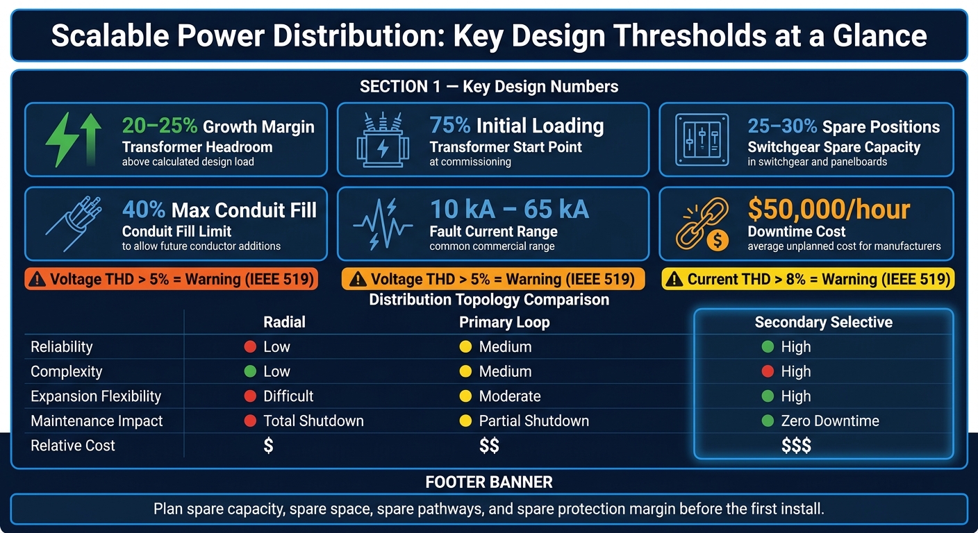
Scalable Power Distribution: Key Design Thresholds & System Comparison
Load Analysis and Capacity Planning for Future Growth
Start capacity planning before you lock in equipment. Use current demand plus a 5- to 10-year growth view so you don’t end up with late redesigns, project delays, or capacity problems sooner than expected. And the starting point matters: plan from measured demand, not installed nameplate capacity.
Measure Current Demand and Identify Load Patterns
Don’t treat nameplate load and peak demand as the same thing. They’re not. Use demand and diversity factors to turn installed capacity into the load the system actually sees in operation.
Power factor matters here too. A low power factor increases current draw and can push you into larger transformers. Industrial motor loads often run at a power factor of 0.8–0.85, and many utilities penalize facilities that fall below 0.90–0.95. VFDs and LED loads can also introduce harmonics, which may mean you need K-rated transformers or harmonic filtering.
For dependable demand data, use interval metering at 15-, 30-, or 60-minute intervals instead of relying on one-off instantaneous readings. Then match that data with a complete one-line diagram and current panel schedules. That makes it much easier to see where capacity is still open before you plan an expansion.
Forecast 5- to 10-Year Expansion Scenarios
Once you’ve documented current demand, map out what the system may need to support over the next 5 to 10 years. Focus on additions that are not already accounted for, such as new production lines, HVAC upgrades, data rooms, and added tenant capacity. Review each scenario on its own so you can see how it changes service and distribution capacity.
Add a 20–25% growth margin above the calculated design load. Then use load-flow and short-circuit analysis software to test each case before construction starts.
Set Headroom and Fault-Current Limits Early
Spare ampacity alone won’t save you. You also need to check available fault current before choosing breakers and switchgear. That value depends on the utility transformer and the impedance of the distribution system. Specifying higher-impedance transformers lowers available fault current on the secondary side and can help keep downstream equipment ratings within range.
Space is part of the plan too. Electrical rooms need enough clearance for future switchgear sections or transformers. If they don’t, the next expansion can force a costly structural redesign.
| Design Element | Initial Provision | Expansion Strategy |
|---|---|---|
| Conduit sizing | 40% fill maximum | Leaves room for additional conductors later |
| Transformers | 75% initial loading | 25% growth margin built in |
These limits shape the architecture choices that come next. Load and fault-current limits set the direction for topology, pathways, and protection.
sbb-itb-501186b
Distribution Architecture and Design Choices That Scale
Once load and fault-current limits are set, the next move is picking a layout that leaves room to grow and keeps outages in check.
Radial, Looped, and Modular Distribution Layouts
A radial system is the simplest and lowest-cost setup. Power moves one way, from source to load. That makes it a fit for tight budgets and sites with low outage tolerance.
A primary loop system adds a second feeder path. It sits in the middle on cost and uptime, which is why it works well for manufacturing or commercial facilities that can't sit through long outages.
Secondary selective systems take redundancy further. Two independent transformer feeds connect through a secondary bus tie, which can deliver zero downtime when the system is sized for the full load. The price tag is higher, but that can make sense in facilities where downtime can top $100,000 per hour.
| Feature | Radial | Primary Loop | Secondary Selective |
|---|---|---|---|
| Reliability | Low (single point of failure) | Medium (redundant feeders) | High (redundant paths to load) |
| Complexity | Low | Medium | High |
| Expansion Flexibility | Difficult (requires shutdown) | Moderate | High (switching allows live growth) |
| Maintenance Impact | Total shutdown required | Partial shutdown for switching | Zero downtime if sized correctly |
| Relative Cost | $ | $$ | $$$ |
The tradeoff is pretty clear. Radial keeps first cost down, but growth usually means more disruption. Loop and secondary selective layouts cost more up front, yet they buy you options later.
Busway, Cable Tray, and Pathway Planning
The way power moves through the building matters just as much as the topology on paper. Busway (busbar trunking) lets you add or move tap-off units anywhere along the run without pulling new cables back to a central panel. If you expect multiple branch points, that can save a lot of labor over time.
There's also a space angle. A 4,000-amp busbar system takes up about one-third of the space of a similar cable-and-tray setup. In packed mechanical rooms or busy production areas, that difference can be hard to ignore.
| Feature | Busway | Cable and Tray |
|---|---|---|
| Installation Speed | Fast (modular) | Slow (labor-intensive pulling) |
| Flexibility | High (tap-offs added anywhere) | Low (new runs required for new loads) |
| Footprint | Compact (roughly 1/3 the size of cable) | Large (requires wide trays and bend radii) |
| Maintenance Access | Easy (visible, bolted joints) | Difficult (cables bundled in trays) |
| Expansion Cost | Low (add a tap-off unit) | High (new cable, tray, and labor) |
For conduit runs, keep initial fill at a maximum 40% so future conductor additions stay straightforward. It's also smart to specify 25% spare conduits in the first build. That one choice can save a painful retrofit later.
Pathways aren't just a routing detail. They shape whether new loads can be added with a small change or a major shutdown.
Protection Coordination and Room Layout
Selective coordination means the protective device nearest the fault trips first, instead of knocking out upstream equipment too. For emergency and legally required standby systems, the NEC requires selective coordination under Article 700.32.
Short-circuit current ratings, or SCCR, need to match the available fault current at every point in the system. In commercial services, available fault current usually falls between 10 kA and 65 kA. That's why the short-circuit study needs to happen during design, not after gear has already been ordered.
Zone Selective Interlocking (ZSI) cuts arc flash energy and trip times, so it's worth calling for early in the design. When you pair ZSI with a maintenance mode switch on main breakers, technicians can work at lower incident energy levels during expansions without changing coordination settings for normal operation.
Electrical rooms also need working clearances that meet NEC Article 110, along with reserved floor space for future switchgear sections or unit substations. It also helps to specify blank sections for future breakers or MCC buckets, so new capacity can be added without replacing the full assembly.
In plain terms, the room should be laid out for the next addition, not just the gear going in today. Those choices affect what transformers, switchgear, and modular equipment can slot in later.
Selecting Equipment for a Modular, Future-Ready System
A layout plan only goes so far if the equipment can't grow with it. If you want a system that can expand in phases, the gear has to be picked with that in mind from day one. Otherwise, a small load increase can turn into a full replacement job later. The goal is simple: each major piece of equipment should handle future growth without forcing you to tear out the whole lineup.
Transformers, Switchgear, Switchboards, and Panelboards
Start with the transformer because it sets the upper limit for everything downstream. A common approach is to commission transformers below full nameplate capacity so they can take on future load without being swapped out too soon. Go too small and you risk thermal runaway. Go too large and you pay for continuous no-load core losses.
In facilities with variable-frequency drives, LED lighting, or dense computer loads, K-rated transformers often make sense. A K-13 transformer can help deal with the harmonic currents those loads create without overheating the windings.
Switchgear and panelboards should also leave room to grow. That usually means spare sections, spare breaker spaces, or both. Bus ratings and interrupting capacity need to match the available fault current at the point where the lineup is selected. If they don't, the whole assembly may need replacement when fault levels are recalculated during expansion.
| Feature | Modular gear | Conventional gear |
|---|---|---|
| Expansion Ease | High; supports phased additions via spare buckets or sections | Low; often requires major rework or replacement |
| Lead-Time Risk | Moderate; standard modules may be faster to source | High; custom-engineered units have long manufacturing timelines |
| Maintenance Access | High; often includes draw-out breakers and ZSI | Moderate; may require total shutdown for minor additions |
| Lifecycle Cost | Lower; avoids premature replacement during growth | Higher; initial savings can be offset by expensive retrofits |
MCCs, Breakers, Relays, and Digital Metering
Once the main gear is set, the motor side needs the same kind of planning. Specify MCCs with spare buckets for future starters or drives so added motor loads don't force you to buy an entirely new MCC.
Feeder breakers also need interrupting ratings that match the available fault current at their installation point. Configurable protective relays help here because you can adjust them as the system grows. They also support selective coordination, so the device closest to a fault trips first instead of taking down more of the system than needed.
Digital metering is one of those areas where many facilities miss an easy win. Meters that track total harmonic distortion (THD), power factor, and demand trends in real time give facility managers a clearer picture of when the next expansion point is coming. If those meters can connect to a building management system or SCADA platform from the start, future monitoring gets much easier.
Sourcing Equipment for Phased Upgrades
Phased upgrades aren't just a design issue. Procurement plays a big part too. Custom-engineered switchgear and transformers can come with long lead times, and that becomes a problem fast when production deadlines are locked in. In that situation, used or reconditioned equipment can be a practical path, not a second-rate one.
Used and reconditioned power transformers often cost 30% to 60% of new pricing, while refurbished units with warranties usually run 50% to 75% of new cost. Before buying a used transformer, ask for:
- dissolved gas analysis (DGA) history
- fault event records
- maintenance records
- PCB-free certification
"The cost of transformer failure typically far exceeds any initial savings from purchasing inadequately assessed equipment." - Electrical Trader
Electrical Trader can help source new and used breakers, transformers, low- to high-voltage gear, and power generation tools for phased upgrades.
Monitoring, Integration, and Key Takeaways
Use Metering and Power Data to Guide the Next Expansion
Once the equipment is installed, monitoring shows when the next expansion should start. Put meters at the service entrance, major feeders, and large motors so you can track load and efficiency over time. That data helps you see transformer and switchgear limits before they turn into bottlenecks.
A good rule of thumb: when a transformer reaches 75% to 80% of rated capacity, or spare switchgear positions fall below 25% to 30%, treat that as a signal to expand instead of waiting for a capacity crunch. Keep watching load trends, then use the historical record to back up capital upgrade requests.
Power quality matters just as much as raw load. Track voltage imbalance and phase current balance so uneven loading across phases doesn't overheat motors or shorten equipment life. If voltage THD goes above 5% or current THD rises above 8%, you're beyond IEEE 519 guidance, which can point to harmonic issues that may call for filtering or K-rated transformers.
Prepare for Solar, Storage, Generators, and EV Charging
New power sources don't just change load. They also change fault current and protection coordination. Before adding solar, storage, generators, or EV charging, run updated load flow and short-circuit studies. Each new source should be treated as a system-wide design change, not a simple add-on. Solar, storage, generators, and EV charging can also introduce harmonics and transients, so event logs help flag sags and swells that matter for protecting PLCs and robotics.
Bring your utility into the conversation early. Large solar generation or EV charging can push fault current past what existing switchgear was built to handle. Selective coordination also needs another check whenever a new DER or large load comes online, so a fault on one circuit doesn't snowball into a larger outage.
Key Takeaways for Building a Scalable Power Distribution System
Scalable power distribution comes down to early planning, modular gear, and steady monitoring. In practice, that means:
- Measure actual demand and forecast 5- to 10-year growth before sizing equipment.
- Build in spare capacity and a modular layout. Plan for a 20% to 25% growth margin on transformers, 25% to 30% spare positions in switchgear and panelboards, MCCs with spare buckets, and reserved busway and conduit paths so you can add capacity without replacing full lineups.
- Check protection settings and fault-duty limits every time the system expands or a new source is added.
- Use monitoring data to time upgrades. Real-time load, power quality, and asset-health metrics turn expansion from guesswork into planned, cost-controlled work.
Unplanned downtime costs manufacturers an average of $50,000 per hour. If you plan for growth from day one and keep a close eye on the system, you're in a much better spot to avoid seeing that number hit your books.
FAQs
How do I size for future growth?
Build spare capacity into the initial design. A common best practice is to plan for 20% to 30% headroom for load growth in service equipment, transformers, and feeders. It also helps to leave about 20% spare breaker spaces in panelboards.
For critical infrastructure, modular equipment can save you a lot of pain later. Uninterruptible power supplies are a good example. It also makes sense to pick switchgear and transformers with enough busbar ampacity and kVA capacity to handle future changes without major upgrades.
When should I expand my power system?
Expand your power system when electrical demand starts to outgrow what your current setup can handle. That often happens after adding production equipment, building out data infrastructure, or scaling up warehouse operations.
It’s also time to expand when load studies show that switchgear, transformers, or panelboards are getting close to capacity, or when the system can’t support planned process changes. In plain terms, if your power setup is starting to feel tight, that’s a clear sign to act before it turns into downtime or safety issues.
Proactive upgrades help maintain reliability and safety. Electrical Trader offers new and used power distribution equipment to support scalable growth.
What changes when I add EV charging or solar?
Adding EV charging or solar can change the electrical picture in a big way. These systems bring new demand and, in the case of solar, power output that can swing throughout the day. That usually means your electrical setup needs a second look.
In some cases, your current capacity won't be enough. When that happens, you may need to upgrade switchgear, transformers, and utility service connections to keep the system safe and code-compliant.
For solar in particular, the equipment also needs to deal with cyclical load profiles, solar-related thermal shifts, and harmonics produced by inverters.





