




Best Practices for Medium Voltage Cable Jointing
Faulty medium voltage (MV) cable joints - rated between 1–35 kV - can lead to serious issues like partial discharges, arc faults, and system failures. Proper installation ensures joints last 20–30 years. Here's what you need to know:
- Safety First: Use arc flash-rated PPE, follow OSHA and NFPA standards, and ensure a dust-free, enclosed workspace.
- Preparation is Critical: Inspect tools, verify component compatibility, and test cables (e.g., Megger testing) before starting.
-
Jointing Methods:
- Heat Shrink: Uses heat for sealing but requires cooling time.
- Cold Shrink: Heat-free, safer for enclosed spaces.
- Tape-Based: Labor-intensive and relies on skill.
- Pre-Molded: Factory-tested, size-specific, and fast to install.
- Material Selection: Match materials to cable type, voltage, and installation conditions (e.g., humidity, UV exposure). Use high-quality, certified components.
- Testing: Conduct pre- and post-jointing tests (e.g., insulation resistance, partial discharge) to ensure reliability.
Straight Through Joint Installation | Heat Shrinkable Joints for MV
sbb-itb-501186b
Safety Measures and Preparation Steps
Creating a controlled and compliant worksite is critical for medium-voltage (MV) jointing. This process leaves no room for mistakes - errors can lead to arc faults, equipment damage, or even severe safety hazards. Proper preparation is the foundation for ensuring joint reliability that lasts for decades.
Worksite Safety Protocols
Start by confirming that all personnel are qualified to handle the specific voltage, cable type, and accessory technology involved. Installers should hold certifications like a Job Skills Training Department (JSTD) card and carry a Job Clearance Card. Additionally, compliance with NFPA 70 and OSHA 29 CFR 1910.269 is non-negotiable.
"No work on MV cable preparation should begin until the installer is confident that all parts and materials are available and are the correct type and size to complete the installation." - Thorne & Derrick
Ensure the splicing area is enclosed and free from dust and wind. If the manufacturer specifies climate control, follow those guidelines. When using propane or butane torches for heat-shrink joints, ventilate the workspace properly. Adjust the flame to a low-intensity blue flame with a yellow tip to avoid scorching. For outdoor terminations, maintain a creepage distance of at least 40 mm (1.6 inches) per kV line-to-line, while indoor setups require a minimum of 25 mm (1.0 inch) per kV.
Once the worksite is secure, focus on equipping yourself with the right protective gear.
Personal Protective Equipment (PPE)
Working with MV systems requires arc flash-rated PPE designed for voltages ranging from 7.2 kV to 42 kV. This includes flame-resistant clothing, insulated gloves, arc-rated face shields, and safety footwear. Proper training on how to use this equipment is just as important as the gear itself. If gas torches are part of the process, add heat-resistant gloves to your kit to guard against burns.
Cable network faults often occur at accessory positions, with poor installation being a frequent culprit. While PPE provides protection during arc flash events, precision and adherence to protocols are essential for preventing such incidents from happening in the first place.
Pre-Work Inspections
Carefully review the manufacturer's installation instructions, as procedures and components may have been updated.
Verify your accessory kit matches the parts list, rejecting any components that are past their expiration date. Check that cable end seals are intact. Once seals are cut, ensure the conductor and internal components remain completely dry. For paper-insulated cables, conduct a moisture test - wet paper tapes are unusable.
Before cutting into the cable, test your tools on a spare cable section to calibrate cutting depths for sheath and screen removal. Even a small nick in the insulation can lead to partial discharge and eventual failure. Align cables precisely, as modern joints demand a straight configuration. If alignment isn’t achievable, do not proceed.
Lastly, conduct Megger testing to confirm the cable's integrity before starting the jointing process. This test provides a baseline measurement for post-jointing comparisons, ensuring you're working with a cable that is fit for the task.
Cable Preparation Techniques
Getting cable preparation right is crucial because most medium-voltage jointing failures can be traced back to this step. In fact, issues with polymeric cable accessories often stem from errors in preparation rather than manufacturing flaws. Even the smallest nick in the insulation can lead to partial discharge, which may eventually cause system failure.
"The early stage of accessory installation is preparation of the cable ends. There is nothing more important than to do this part of the work accurately and skilfully." - Thorne & Derrick
Start by thoroughly cleaning and drying a sufficient length of the cable sheath near the work area. When removing the sheath, always use specialized, guarded tools to avoid damaging the copper wires, tape, or armor beneath. This careful preparation lays the groundwork for effective cleaning, stripping, and conductor alignment.
Cable Cleaning and Stripping
Modern medium-voltage cables have a semiconductive screen layer that is typically 0.3 mm to 0.6 mm (0.012 to 0.024 inches) thick. How you remove this layer depends on whether it is peelable or bonded to the insulation.
- Peelable screens: Use a depth-guarded knife set slightly shallower than the screen thickness to score the surface. Alternatively, a round file can create a clean edge without direct knife contact.
- Bonded screens: A spiral-motion stripping tool works best. Adjust it so the removed strip shows two-thirds black screen and one-third insulation, ensuring complete removal without cutting too deeply.
When stripping the insulation, spiral-cut tools provide the cleanest edges. For XLPE insulation, warming it beforehand can make cutting easier. Once the conductor is exposed, remove any remaining semiconductor layers using a twine sawing motion to avoid damaging the metal strands.
Final cleaning is essential. Use the recommended cleaning agent to wipe the insulation, always moving toward the conductive screen to prevent dragging conductive debris onto the clean surface. Discard any cloth that touches the screen - never reuse it on the insulation.
For the conductor, clean off oxides with a wire brush and immediately apply an oxide inhibitor before installing connectors. After cutting, remove any sharp edges or burrs to prevent stress points that could lead to electrical failure.
Once the cable surfaces are spotless, you can move on to aligning the conductors with precision.
Conductor Alignment and Preparation
Straight alignment is non-negotiable for cable joints. Any deviation from a straight configuration can compromise the joint's integrity. If the cables cannot be aligned properly, the jointing process should not proceed.
Overlap the cables by about 4 inches (100 mm) and mark a reference line at the center of the overlap. This ensures the conductors meet at the correct point. For 3-core cables, provide adequate support while separating the cores to avoid damaging the insulation.
Before making the final connections, verify the phase sequence. Use the reference line to cut the cores precisely, ensuring they are properly shaped and positioned. After crimping or soldering the conductors, remove any sharp edges or projections to maintain a smooth profile. This attention to detail is key to achieving a reliable and durable joint.
Common Jointing Methods
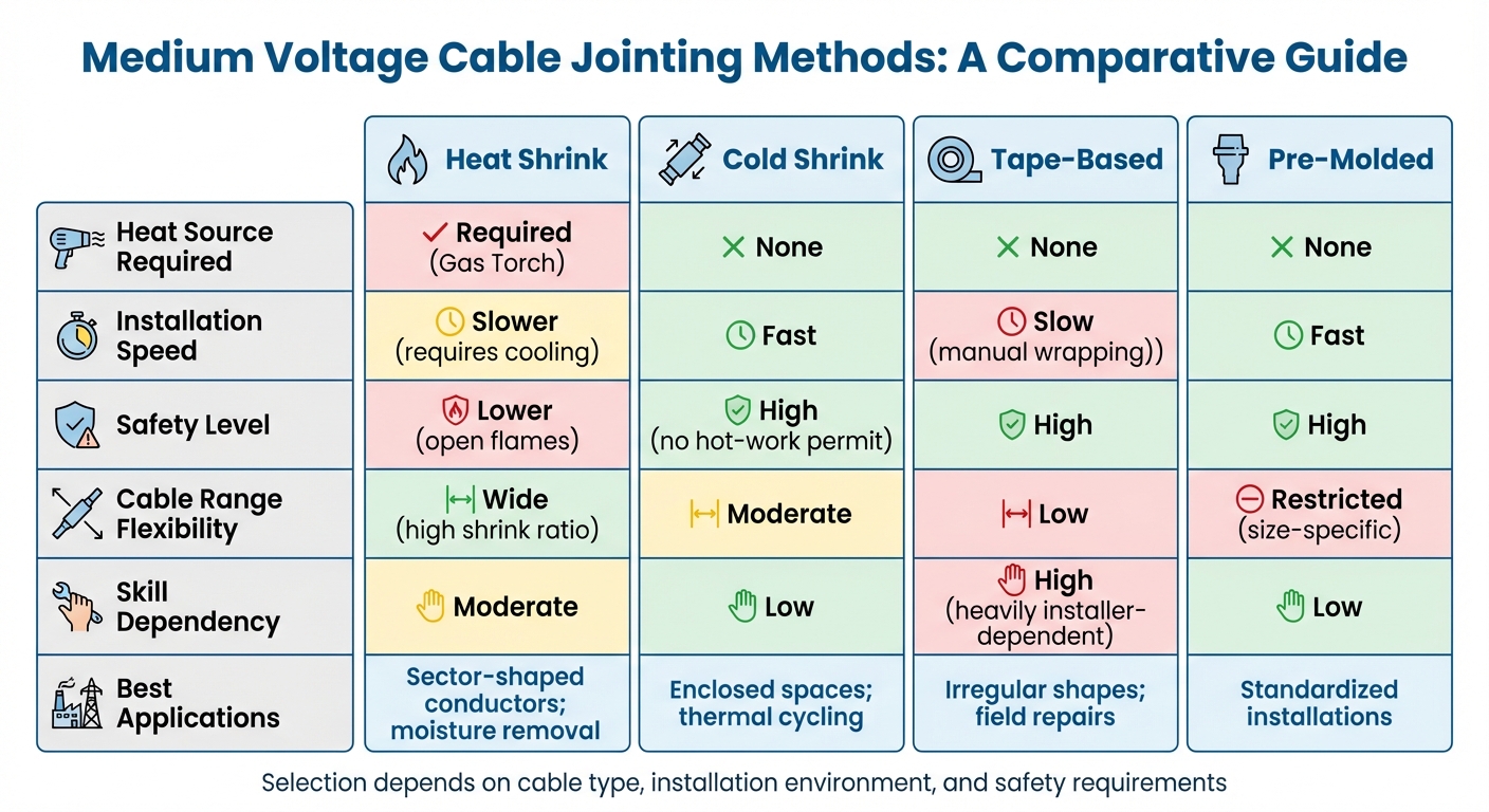
Comparison of Medium Voltage Cable Jointing Methods
When it comes to connecting cables, selecting the right jointing method is crucial. The four main techniques - heat shrink, cold shrink, tape-based, and pre-molded joints - each serve specific needs depending on the conditions at the worksite, the cable's design, and safety requirements.
"The object of the cable jointing exercise is to replace all the materials that were removed to joint the conductors and replace them in such a way as to replicate the cable as closely as possible to its original state." - Norman Poulter, Managing Director, Shrink Polymer Systems
Each method strives to restore the cable's original structure and ensure long-term durability. Let’s explore what sets these methods apart.
Heat Shrink Jointing
This method uses heat to shrink polyolefin tubes over cable connections. A gas torch activates mastic seals, which secure the joint and expel moisture - essential in damp environments. It’s a flexible approach, suitable for a variety of cable sizes and sector-shaped conductors.
The process is straightforward: slide the heat shrink tubing onto the cable, apply connectors with stress control mastic, and shrink the tubing from the center outward to avoid trapped air. Use a propane or butane torch with a soft blue flame and maintain a 45° angle, keeping the flame 6 to 8 inches (15 to 20 cm) away to prevent scorching. Visible mastic at the tube ends confirms a moisture-tight seal. However, heat shrink joints require a cooling period before they can handle mechanical strain, and open flames may necessitate "hot-work" permits in industrial settings [14, 19, 16].
For those seeking a safer, heat-free alternative, cold shrink jointing offers a compelling option.
Cold Shrink Jointing
Cold shrink jointing, pioneered by 3M over three decades ago, eliminates the need for heat. Pre-stretched tubes on removable plastic cores are positioned over the cable, and pulling the core tab allows the material to shrink into place using its elastic memory.
Chris Dodds, Sales & Marketing Manager at Thorne & Derrick, highlights the method’s reliability:
"3M Cold Shrink has a molecular permanent set which ensures constant radial pressure is exerted on the cable for the duration of the cable joints life."
This method is ideal for enclosed or hazardous environments, as it avoids the risks associated with open flames. The silicone or EPDM materials adapt to thermal expansion and contraction, maintaining consistent pressure. However, it’s essential to check "use by" dates and handle the components carefully to preserve their integrity. Compared to heat shrink, cold shrink jointing reduces the risk of installer error and offers a faster, safer solution [16, 18].
Tape-Based Jointing
In this approach, self-fusing tapes are manually wrapped around the cable connection to create a watertight seal. The tape should be applied with a 50% overlap and stretched to half its width, filling voids and managing electrical stress. For connectors with indentations, stress-relief mastic or a yellow void-filling compound is essential to prevent electrical discharge. Air pockets can lead to failure at approximately 4 kV (11 kV cables), 6 kV (24 kV cables), or 9 kV (36 kV cables).
While tape-based jointing can be effective, it’s labor-intensive and heavily reliant on the installer’s skill. Even experienced technicians might inadvertently leave air pockets, which can cause partial discharge and eventual failure. This has led many utilities to prefer more consistent, factory-engineered solutions.
Pre-Molded Joints
Pre-molded joints are pre-manufactured components designed to manage electrical stress using the Faraday Cage principle. Rubber-ribbed moldings ensure any trapped air has minimal potential difference, preventing electrical discharge.
Installation is simple: apply silicone grease to the cable and push the joint into place in one continuous motion to achieve the correct fit. These joints eliminate the need for stress-relief tapes and are factory-tested for reliability. However, they are size-specific, meaning precise measurements are required when ordering. They can also be bulky for three-core cables. Despite these limitations, pre-molded joints are a dependable choice for standardized installations where consistency is key [14, 18, 17].
Here’s a quick comparison of the key features of these methods:
| Feature | Heat Shrink | Cold Shrink | Tape-Based | Pre-Molded |
|---|---|---|---|---|
| Heat Source | Required (Gas Torch) | None | None | None |
| Installation Speed | Slower (requires cooling) | Fast | Slow (manual wrapping) | Fast |
| Safety | Lower (open flames) | High (no hot-work permit) | High | High |
| Cable Range | Wide (high shrink ratio) | Moderate | Low | Restricted (size-specific) |
| Best For | Sector-shaped conductors; moisture removal | Enclosed spaces; thermal cycling | Irregular shapes; field repairs | Standardized installations |
Each method has its strengths, and the choice often depends on the specific requirements of your project.
Materials Selection Criteria
Picking the right materials for medium voltage cable jointing is all about ensuring reliability over time. Even with perfect installation techniques, using the wrong materials can lead to thermal failures, moisture intrusion, or electrical breakdowns.
"MV network reliability depends on both the cable and its accessories." - Europacable
As previously discussed, even minor imperfections in a joint can lead to failure. Choosing the right materials is your best safeguard. Three key factors play a role in making the right choice: compatibility with your cable type, suitability for the installation environment, and the dependability of your supplier. Let’s break these down.
Compatibility with Cable Type
First, materials need to align with the voltage rating of your system. Medium voltage accessories are designed for specific "highest system voltage" (Um) levels, typically between 7.2 kV and 42 kV. Using a joint rated below your system voltage can result in early failure.
You also need to match the insulation type. For example, polymeric cables like XLPE or EPR require different jointing materials than older PILC (paper-insulated lead-covered) cables. Specialized transition joints are necessary when connecting these different cable types. Additionally, the semiconductive screen of the cable matters - bonded screens and peelable (non-bonded) screens require different preparation techniques.
Compression connectors are another area where precision is crucial. The die code must match the lug code exactly. If mismatched, connection resistance can jump from 0.15 mΩ to 0.45 mΩ, causing temperature rises of 45°C at 100 A instead of the acceptable 15°C.
When it comes to stress control, you’ll need to choose between molded shapes and stress-control tapes or tubes. Silicone rubber joints with heat-dissipating additives, for instance, can run 10°C to 15°C cooler than the conductor in 15 kV setups, which helps extend their service life.
Environmental Considerations
The installation environment is another critical factor. For outdoor terminations, silicone is often preferred over EPDM. Silicone doesn’t form conductive carbon paths when degraded by UV radiation or partial discharges. In areas with pollution or salty coastal air, silicone’s ability to maintain surface hydrophobicity helps limit leakage currents even after being exposed to severe wetting.
That said, silicone’s gas permeability, which helps eliminate trapped air bubbles, can make it unsuitable for the joint’s outer protective tube. EPDM, with its lower water vapor permeability, is often a better choice for outer protection. High humidity environments (above 80%) add another layer of complexity, as they increase the risk of surface tracking on insulation.
"Trapping airborne moisture or dust inside the layers of a termination is fatal, as humidity above 80% significantly increases the risk of surface tracking." - Richard Zi, General Manager, ZW Cable
Temperature extremes also affect material selection. Silicone-based cold shrink materials are easier to install in cold weather due to their elasticity, which eliminates the need for additional heat. Silicone also expands and contracts with the cable during temperature fluctuations, maintaining constant pressure. Push-on splices, by contrast, can lose up to 90% of their initial installation pressure during heat cycles.
In chemically harsh environments or areas where open flames are restricted, cold shrink elastomeric tubes are often the safer option.
Sourcing Reliable Materials
The quality of your materials starts with the supplier. Every joint body should pass factory production tests, such as Partial Discharge (PD) and AC withstand tests, before being used. A manufacturing date stamp is a good sign that the component has undergone these critical tests.
"A well-designed splice combined with high-quality manufacturing, and a correct installation can remove the traditional splice weak link in a cable." - George Fofeldea, Power Engineer, 3M Canada
Premium cold shrink joints often use silicone rubber instead of EPDM, as silicone offers better thermal dissipation and maintains active seal pressure during thermal cycling. High-quality joints also feature thick molded semi-conductive outer shells (3–4 mm), which provide both physical protection and electrical continuity. These designs meet IEEE 592 "nail test" standards for durability. For example, Prysmian Elaspeed MV cable joints have passed external water pressure tests of up to 45 psi.
When sourcing materials, platforms like Electrical Trader (https://electricaltrader.com) can connect you with trusted manufacturers offering new and used power distribution equipment. Working with specialized distributors ensures you get third-party type-tested components that meet industry standards.
Look for BASEC (British Approvals Service for Cables) certification or equivalent marks to ensure compliance and avoid non-compliant products. Also, use approved cleaning materials like high-purity isopropyl alcohol and non-conductive abrasive cloths for preparation.
Pre- and Post-Jointing Testing Procedures
Thorough testing is the backbone of ensuring cable joint reliability and safety. Pre-jointing inspections help catch potential problems early, while post-jointing tests confirm the joint can withstand actual operating conditions.
"Cable network faults are often located at accessory positions, and in the majority of cases the cause of the fault is inaccurate or poor-quality installation by the jointer." - Europacable
Cable failures tend to happen at termination points rather than mid-span. This makes testing, both before and after jointing, absolutely critical.
Pre-Jointing Inspections
Before starting the jointing process, a final pre-jointing check ensures everything is set up correctly. Key steps include:
- Matching the jointing kit to the cable type and size: Double-check compatibility .
- Inspecting components: Verify that all parts are present and within their "use by" date.
- Checking cable end seals: Ensure the seals are intact, and confirm the conductor and internal components are completely dry.
- Testing tool settings: Use a spare cable length to confirm the cutting depth for screen removal is correct .
For bonded screens, the removed strip should reveal about two-thirds black screen and one-third insulation. This ensures complete removal without damaging the insulation.
"A knife cut may be invisible but will almost certainly become a future failure site, possibly immediately the cable system is energised but certainly after several months or years." - Thorne & Derrick
Perform a Megger test on each cable segment to establish baseline insulation resistance. For a 15,000V rated cable, the value should be at least 5,000 Megohms when tested at 2,500V DC. Additionally, conduct phase identification to ensure proper alignment during the jointing process. These steps build on earlier safety protocols, laying the groundwork for a reliable connection.
Post-Jointing Electrical Testing
Once the joint is complete, post-jointing tests confirm its readiness. Start with an Insulation Resistance (IR) test using a Megger to ensure insulation integrity hasn’t been compromised by moisture or contaminants. For medium-voltage cables, this test typically uses 2,500V DC.
Follow this with High-Voltage (Hi-pot) withstand testing. This involves applying elevated voltages - AC, DC, or Very Low Frequency (VLF) - to simulate operational stresses . For new installations, the test voltages are much higher than normal operating levels, such as 35 kV for 5 kV cables, 40 kV for 8 kV cables, and 55 kV for 15 kV cables. Hold the voltage steady for at least one minute to monitor leakage current.
"A continuously rising current value, while holding at a constant voltage level, indicates an imminent failure." - PAKTECHPOINT
Partial Discharge (PD) testing is another essential step. It identifies tiny air pockets or "electrical treeing" within the joint that could degrade insulation over time. A successful PD test typically shows discharge levels below 10 pC at 1.73 U₀.
Additional tests include:
- Shield continuity testing: Ensures the metallic screen is properly bonded, with resistance not exceeding 10 ohms per 1,000 feet.
- Contact resistance measurement: Verifies that crimped connectors have low resistance to prevent overheating, using a micro-ohmmeter .
- Tan Delta testing: Provides a diagnostic baseline for assessing insulation health .
"Relying solely on visual inspection is insufficient because you cannot see inside the completed layers." - Richard Zi, General Manager, ZW Cable
After completing high-voltage tests, ground the conductors for a duration equal to four times the test period to safely discharge any residual energy. Lastly, confirm that all test equipment is supported by up-to-date calibration certificates before use.
Conclusion
A flawless jointing process is the backbone of reliable Medium Voltage (MV) systems, and it all starts with meticulous cable end preparation. This step is absolutely critical and demands precision at every turn. Using specialized tools - instead of unguarded knives - ensures safety and accuracy. Equally important are strict cleanliness protocols and proper conductor alignment, which together form the basis of a dependable joint.
The consequences of errors can be severe. For instance, using the wrong crimping die can cause connection resistance to jump from 0.15 mΩ to 0.45 mΩ. At 100A, this increase can lead to temperature spikes from 15°C to a scorching 45°C. Many early cable failures stem from workmanship issues, such as voids or damage caused by improper tools. This underscores the importance of careful preparation.
Proper training is non-negotiable. Installers must be trained specifically for the voltage and cable technology they are working with. Without proper expertise, the risks are too high, and unqualified individuals should not proceed. Environmental conditions also play a key role - humidity levels above 80% can dramatically increase the chance of surface tracking during installation.
To help professionals meet these stringent standards, Electrical Trader offers tools and materials from leading brands like Nexans, Prysmian, 3M, ABB, Pfisterer, and Cembre. Their product range includes specialized cable preparation tools, matched crimping components, and accessories for 11kV, 33kV, and even 66kV distribution systems. With the right equipment and adherence to best practices, installers can ensure system integrity, enhance safety, and extend the service life of MV systems.
FAQs
How do I choose the right MV joint type for my site?
To choose the right medium voltage (MV) joint type, it's crucial to have a solid understanding of the system voltage, cable type, and accessory technology. Make sure to carefully review the manufacturer's installation instructions to ensure the joint is compatible with your cables and the specific conditions at your site. Don’t overlook environmental factors, such as exposure to extreme conditions, as these can impact the joint's performance. Always follow best practices to ensure the joint operates safely and performs reliably.
What are the most common prep mistakes that cause MV joint failures?
Medium-voltage (MV) joint failures often stem from a few key preparation mistakes. These include inadequate cable end preparation, improper cleaning and drying of the cable sheath, and incorrect handling or installation of accessories. Such errors can lead to insulation damage, compromised termination quality, and, ultimately, joint failure. Paying close attention to these preparation steps is crucial for ensuring the joint's reliability and safety over time.
Which post-joint tests best predict long-term reliability?
Post-joint tests that help forecast long-term performance include partial discharge measurements, tangent delta testing, and thermal aging assessments. These methods focus on key aspects such as insulation strength and dielectric behavior over time, providing valuable insights into the joint's durability and reliability.





