5 Factors for High Voltage Cable Compatibility
A high-voltage cable is only a fit if all five checks line up: voltage rating, insulation, grounding, ampacity, and installation details. In U.S. systems, high voltage often starts above 35 kV, and one mismatch can lead to heat buildup, partial discharge, accessory failure, or a fault event.
Here’s the short version: match the cable to the system’s highest voltage, not just its nominal voltage. Then check whether the insulation type fits the duty, whether the sheath and bonding setup fit the grounding method, whether the cable can carry load in the actual site conditions, and whether joints and terminations match the full cable system. That matters because duct installs can drop ampacity to about 65%, grouping can cut it by up to 50%, and screen losses can trim thermal rating by 15% to 25%.
If I were screening a cable fast, I’d check these five points first:
- Voltage class: The cable and accessories must match the system’s maximum voltage
- Insulation type: XLPE, EPR, and paper/oil each fit different use cases
- Grounding and bonding: Sheath current, sheath voltage, and fault duty all change with bonding method
- Ampacity and heat: Soil, ducts, spacing, and sun all change current rating
- Installation and accessories: Many failures start at joints, terminations, or interface contamination
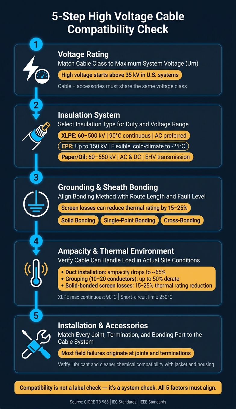
5-Step High Voltage Cable Compatibility Check
High Voltage Electric Cables Explained: Anatomy, Materials & Safety
sbb-itb-501186b
Quick Comparison
| Factor | What to check | Common failure if missed |
|---|---|---|
| Voltage rating | Cable class vs. highest system voltage | Insulation overstress |
| Insulation | Dielectric type, temperature limit, AC/DC fit | Partial discharge, early aging |
| Grounding/bonding | Sheath sizing, bonding layout, SVLs | Sheath overheating, overvoltage, losses |
| Ampacity | Load, ambient heat, soil/duct conditions, grouping | Overheating, reduced life |
| Installation/accessories | Route fit, joint/termination match, clean assembly | Accessory breakdown, moisture or air-gap issues |
Put simply, compatibility is not a label check - it’s a system check. The rest of the article walks through each factor in the order I’d review them before purchase and installation.
Why Compatibility Matters in High Voltage Systems
These risks show why compatibility goes far beyond matching a nameplate rating. If the cable’s insulation, shielding, thermal limits, or accessories don’t fit the actual system conditions, the outcome can be anything from nuisance tripping to major failure.
Voltage rating is just the starting point. If the conductor and insulation don’t work well together, electric field hotspots can form and trigger partial discharge (PD). Over time, PD eats away at the dielectric until the cable fails.
Heat makes things worse. High ambient temperature, tight bundling, and dry burial speed up XLPE aging and cut ampacity.
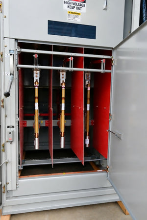
Joints and terminations are often where things go wrong first. They rely on exact field control and careful manual assembly, which leaves more room for installation mistakes.
"Generally, the accessories are considered the more critical part of the cable system because of many key parameters such as design, electric field control, materials used, and assembly with the possibility of human error during installation." - CIGRE Technical Brochure 968
Contamination at the cable-accessory interface can also cause trouble fast. Moisture, oil, dust, or other debris may stop proper interface pressure from forming and create air gaps. Those gaps can lead to dielectric breakdown. In service, a large share of accessory failures is linked to poor workmanship during installation, not material defects.
The shield has to handle the available ground fault current too. If it’s undersized, it can fail during a fault. And in solidly earthed single-core systems, missing cross-bonding can cut thermal capacity.
With those risks laid out, the first compatibility check is the cable’s voltage rating.
1. System Voltage Level and Cable Voltage Rating
Now that the system risks are on the table, start with the most basic fit check: the voltage rating.
Voltage Class Match
Begin with the cable voltage rating. It needs to line up with both the system's nominal voltage and its maximum system voltage.
If you pick a cable rated below the system's maximum voltage, the insulation can be pushed too hard. That can lead to early failure.
Insulation Level
Next, check that the insulation level fits the system's maximum voltage and the transient overvoltages it may see. Before commissioning, verify that the cable has passed the required factory and field tests.
The cable and its accessories also need matching ratings, because the system works as one electrical assembly.
Once the voltage rating is confirmed, move to the next check: insulation system compatibility.
2. Insulation System and Dielectric Compatibility
Once the system voltage is set, the next job is to make sure the insulation works for the voltage class, operating temperature, and dielectric stress in the installation.
Insulation and Dielectric Fit
The main high-voltage cable insulation types are XLPE, EPR, and paper-insulated designs such as PILC/SCFF. XLPE is the leading choice for fixed high-voltage installations and accounts for most installations below 220 kV. It’s often chosen because it offers high dielectric strength and very low dielectric loss.
EPR is a better fit for flexible, vibration-prone applications, such as mining trailing cables and equipment connections. The tradeoff is that it has higher dielectric losses than XLPE.
For extra-high-voltage service above 220 kV, paper-insulated cables still hold a big share. In fact, they represent 75% of installations in the 315–500 kV range.
Make sure the insulation’s dielectric strength is above the maximum electric stress and any transient overvoltages the system may see.
After that, match the insulation level and sheath bonding to the system grounding method.
3. System Grounding Method and Insulation Level
The grounding method sets the insulation level you need and helps determine the right sheath design for the cable system. Once that part is set, the next step is to check how the bonding method changes sheath voltage, sheath current, and system losses.
Grounding and Sheath Coordination
The cable's metallic sheath works as a shield and must be sized to carry fault current safely to earth. The bonding method you select directly affects sheath current, sheath voltage, and losses.
"Incorrectly configured sheath bonding systems may lead to cable system failures, including unintended cable rating reductions, additional system losses, and possibly create safety risks." - CIGRE Working Group B1.50
There are three main bonding approaches, and each comes with a clear trade-off:
| Bonding Method | Sheath Current | Sheath Voltage | Typical Application |
|---|---|---|---|
| Solid bonding | High (causes losses) | Low | Short distribution circuits |
| Single-point bonding | Zero | High at open end | Short cable lengths |
| Cross-bonding | Minimized | Low (cancelled out) | Long HV/EHV circuits |
With solid bonding, sheath voltage stays low, but sheath current is high, which adds losses. Single-point bonding removes sheath current, but voltage can build up at the open end. Cross-bonding is often used on long HV/EHV circuits because it cuts both sheath voltage and circulating-current effects.
If single-point bonding is used, clamp transient voltage with SVLs at the open ends.
At 66 kV and above, sheath bonding has to be engineered for the project, and insulation coordination must account for transient overvoltages. For single-point bonding, install Sheath Voltage Limiters (SVLs) at the open ends or at cross-bonding points to protect the cable jacket and accessories.
After grounding and bonding are aligned, the next check is simple: can the cable carry the load without overheating?
4. Load Profile, Ampacity, and Thermal Environment
Once voltage, insulation, and bonding line up, the next check is simple: can the cable carry the load without getting too hot? Ampacity is a heat limit. If the cable can’t shed heat, the insulation starts to age and break down. For XLPE, continuous operation is 90°C (194°F), and short overloads are usually capped at 105°C (221°F).
Site conditions can change ampacity fast. A cable in free air can carry more current than the same cable in an underground duct. In fact, a duct installation can cut ampacity to about 65%. Soil matters too. Soil thermal resistivity usually falls between 0.5 and 2.5 K·m/W, but under steady heavy load, the soil can dry out and climb to about 3.0 K·m/W. When that happens, heat gets trapped and ampacity drops. On tight urban routes, Fluidized Thermal Backfill (FTB) helps because its thermal properties are defined, which makes heat flow easier to predict.
Grouping is another big factor. Put 10 to 20 conductors in one raceway, and mutual heating can force an ampacity derate of up to 50%. Higher soil temperature cuts the margin even more on heavily loaded underground runs. And in solid-bonded three-phase flat layouts, losses in the metallic screens can trim the cable’s thermal rating by 15% to 25%. Those bonding losses aren’t a side note. They need to be part of the thermal rating from the start.
There’s one more limit to check: short-circuit duty. The cable has to withstand fault current without the XLPE going past 250°C (482°F).
Next, check whether the installation method and accessories match the site conditions.
5. Installation Method, Environment, and Accessory Compatibility
Installation is what turns a cable design on paper into something that has to work in the field. Even if the voltage, insulation, grounding, and thermal design are right, a poor installation fit can still cause problems later.
Thermal and Installation Suitability
Installation method has a direct effect on heat dissipation. Dry ducts don’t shed heat well, so they lower current capacity compared with direct burial. On exposed runs, sunlight adds extra heat load and can push temperatures higher than expected. In those cases, you may need shading or a larger conductor size. When site data isn’t available, standard calculations assume solar intensity of 1,000 W/m².
Next, line up the bonding arrangement and accessory hardware with the actual route being installed.
Grounding and Sheath Bonding Coordination
Sheath bonding needs to match the physical layout of the route from the beginning. If that decision comes late, small layout issues can turn into installation problems, testing delays, or both.
This is also where accessory mismatches tend to show up first. Joints and terminations should match the cable insulation system so the interfaces stay stable through the full service life.
Accessory Compatibility and Post-Installation Testing
Every accessory needs to match the system voltage class and the test standards that apply to the circuit. That includes joints, terminations, bonding parts, and other connection hardware.
After installation, test the full circuit before commissioning. That step helps confirm the cable, accessories, and installed layout all work together as intended.
Use the tables below to check installation method, site conditions, and accessory class before procurement.
System Voltage Rating Reference Table
Use this table to map nominal system voltage to the minimum cable class you can accept.
The key point is simple: use the highest system voltage, not the nominal value, as the floor for cable rating. The cable, transformers, breakers, and terminations should also line up on impulse withstand levels. If one part of the system falls short, that mismatch can come back to bite you.
Common North American voltage classes are listed below.
| System Nominal Voltage | Highest System Voltage | Cable Voltage Rating |
|---|---|---|
| 69 kV | 72.5 kV | 69 kV |
| 115 kV | 121 kV | 115 kV |
| 138 kV | 145 kV | 138 kV |
| 230 kV | 242 kV | 230 kV |
Any cable rated below the highest system voltage is not compatible with that system class. Before procurement, ask for type and routine test certificates, including partial discharge and high-potential results.
Insulation Types at a Glance
After voltage rating, the next step is matching the insulation to the job. XLPE, EPR, and paper/oil do not act the same when heat builds up, the cable has to bend, or test methods come into play.
| Insulation Type | Typical Voltage Range | Thermal Limit (Continuous) | AC/DC Suitability | Advantages | Limitations | Typical Uses |
|---|---|---|---|---|---|---|
| XLPE | 60 kV to 500 kV | 90°C (194°F); 250°C (482°F) short-circuit | AC preferred; DC testing can damage insulation | Low cost, low weight, easy to repair, halogen-free | Stiff, high thermal expansion, sensitive to DC testing | Standard HV land installations, direct burial |
| EPR | Up to 150 kV (limited) | 90°C (194°F); 250°C (482°F) short-circuit | AC | Flexible, vibration resistant, ozone resistant, cold-climate rated to -25°C (-13°F) | Higher cost, higher dielectric losses | Mining, vibrating equipment, tight bends, cold climates |
| Paper/Oil (SCFF/HPFF) | 60 kV to 550 kV | 90°C (194°F) | AC and DC | Proven long-term reliability, no thermal expansion issues, DC compatible | Heavy lead sheath, requires fluid pressure management | U.S. HPFF pipe-type systems, EHV transmission, DC links |
In practice, EPR is the pick when the route needs more bend and movement. That makes it a common fit for mining work, vibrating equipment, and runs with tight turns.
For most fixed, direct-buried utility installations, XLPE is still the default choice. It costs less, weighs less, and is easier to repair, which matters a lot once you leave the spec sheet and get into the field.
Paper/oil systems, including SCFF and HPFF, still have a place when long service life and DC use matter. The tradeoff is pretty plain: they’re heavier, and they need fluid pressure control.
After insulation, the next compatibility check is grounding and sheath bonding.
Grounding Method and Sheath Bonding Comparison
Grounding can change cable needs even if the system voltage doesn't change.
That catches people off guard. A system may look the same on paper, but the grounding setup can push you into a higher insulation class. It can also cut ampacity because of sheath losses. So this isn't just a fault-study detail. It affects cable selection in a very direct way.
In ungrounded or resonant-grounded systems, a ground fault can push the unfaulted phases up to line-to-line voltage. When that happens, the cable needs a higher U₀ rating.
| Grounding Method | Fault Level | IEC Category | Impact on Cable Insulation | Circulating-Current Risk | SVL Requirement |
|---|---|---|---|---|---|
| Solidly Grounded | Very High | A or B | Standard U₀ | High - sheath must handle return fault current | Low |
| Low-Resistance | Moderate/Controlled | A or B | Standard U₀ | Moderate - depends on circuit length and load | Needed for temporary overvoltages during faults |
| Resonant (Arc-Suppression) | Very Low | C | Higher U₀ required | Low | SVLs must withstand overvoltage for extended fault duration |
| Ungrounded/Isolated | Very Low (Capacitive) | C | Highest stress - full line-to-line voltage on unfaulted phases | Low | Higher continuous operating voltage rating required |
Sheath bonding also changes the picture.
Solid bonding can create circulating sheath currents, and those currents can lower ampacity. Single-point bonding gets rid of those circulating currents, but it can push sheath voltage up at the open end. Cross-bonding helps limit both issues on long circuits. In plain terms, you're always trading one thing against another.
That’s why sheath losses have to be included in ampacity calculations. Skip them, and the cable may look better on paper than it will in service.
For single-core cables, bonding needs extra care. Above 150 kV, single-core cables are usually the practical choice.
Ampacity and Installation Condition Comparison
Check ampacity in the actual installed setup, not just on the datasheet.
That matters because installation method can change ampacity almost as much as cable size. A cable run in an open-air tray will usually carry the most current. Put that same cable in a buried duct bank, and its current rating can drop hard. Same cable, very different result.
Direct-buried cables often cool better than duct bank runs. But there’s a catch: if the soil dries out, its thermal resistance goes up, and ampacity drops with it. When you compare installation conditions, use K·m/W as the common unit for thermal resistivity.
Spacing matters too. Pack circuits too close together and heat builds up fast. For example, four buried trefoil circuits spaced 0.2 m apart lose about 32% of ampacity compared with one isolated circuit.
| Installation Method | Thermal Conditions | Relative Ampacity | Main Derating Factors |
|---|---|---|---|
| Tray (In Air) | Ambient air: 104°F (40°C); solar up to 1,000 W/m² | Highest | Solar radiation absorption; conductor spacing and diameter ratio |
| Conduit-in-Air | Ambient air + internal air gap in conduit | Lower than tray | Trapped air raises thermal resistance; conduit material (PVC vs. metal) |
| Direct-Buried | Soil temp: 77°F (25°C); soil thermal resistivity: 0.8–2.5 K·m/W | Moderate | Soil dry-out; mechanical protection (SWA) |
| Duct Bank (Buried) | Ambient soil + duct wall + air gap | Lowest (air-filled) | High thermal resistance of trapped air; fill with bentonite or water to improve rating |
These installation conditions also affect accessory choice and bonding layout.
Environment and Accessory Matching Table
Route conditions are the last compatibility check. The installation setting shapes both the cable build and the accessory set.
If the route mixes overhead and underground sections, choose surge arresters and protection systems based on the circuit’s overvoltage profile and auto-reclose behavior. For submarine routes, use flexible factory joints and sealing ends that can deal with mechanical tension during laying.
Use the table below to line up each route type with the right cable construction and accessory package.
| Installation Environment | Cable Construction | Accessories | Compatibility Risks |
|---|---|---|---|
| Direct-Buried | XLPE with metallic sheath (lead/aluminum/copper) | Joints, outdoor terminations, surge arresters | Corrosion, joint stress, moisture ingress |
| Ductbank (Pipes) | XLPE in ducts; HPFF in steel pipe | Stop joints (HPFF), splices, bonding accessories | Impedance variation, heat limits, pulling stress |
| Submarine | XLPE or SCFF (reinforced sheath) | Flexible factory joints, repair joints, sealing ends | Interface water ingress, mechanical tension during laying |
| Mixed overhead/underground | XLPE transition cables | Transition joints (cable-to-OHL), surge arresters | Overvoltage profile mismatch between overhead line and cable |
| Tunnel | XLPE or SCFF (single core); GIL also used | Fire-retardant terminations, cross-bonding kits | Air temperature fluctuations, accessory support alignment |
Match the accessory voltage class, insulation system, and bonding method.
Practical Engineering Checklist
Before you approve any high-voltage cable for service, walk through these five checks in order. This is the last pass after the comparison tables, and it helps confirm the cable, system, and accessories still match before procurement.
Start with voltage rating. Make sure the cable's rated voltage meets or exceeds the system's maximum operating voltage (Um) and matches the accessory class.
Check insulation and service duty. Match the insulation system to AC or DC service, and verify that it complies with the applicable cable standard.
Review grounding method and sheath bonding. The grounding and bonding setup should fit the system fault level, route length, and the level of sheath-current control the project calls for.
Confirm ampacity under all load conditions. Check continuous, overload, and seasonal ampacity based on the actual installed thermal conditions.
Then check accessories and the installation environment. This is where many field problems start. Accessories are the most failure-prone part of the system, so every joint and termination needs to match the cable's voltage class, insulation system, and bonding method. Also verify that any lubricants and cleaning agents used during installation are chemically compatible with both the cable jacket and the accessory housing. If you're sourcing through Electrical Trader, cross-check each cable, joint, and termination against the same voltage, insulation, and bonding requirements.
Use these checks as the final gate before purchase and installation.
Conclusion
High-voltage cable compatibility comes down to five connected factors: voltage class, insulation system, grounding method, thermal performance, and installation and accessory fit. You can’t look at these one by one and hope for the best. They work as a set.
When those pieces line up, the result is a cable system that can deliver 20 to 40 years of service life. Getting that match right helps cut premature aging, outages, and rework.
FAQs
How do I find the system’s highest voltage?
Check your equipment’s rated voltage and make sure it’s above the system’s maximum operating voltage. For example, a 13.8 kV system will often use equipment rated for 15 kV.
You can verify this on the equipment nameplate or in the specification sheet.
When should I choose XLPE instead of EPR?
Choose XLPE over EPR when you need better electrical and thermal performance, long-term durability, and support for high fault levels, direct burial, or fire-critical applications.
XLPE gives you higher dielectric strength, better heat resistance, and is the standard choice for most fixed industrial installations.
Why do cable joints and terminations fail so often?
Cable joints and terminations often fail because of installation mistakes, rough handling, and poor workmanship. Jointing is a tricky job, and even small slips from the manufacturer's instructions can leave weak spots that break down over time.
Some of the most common problems are inadequate insulation, improper crimping, contamination, and “hot” joints. Each of these can weaken the connection and increase the risk of faults.